EP1512904B1 - Projecteur pour véhicules - Google Patents
Projecteur pour véhicules Download PDFInfo
- Publication number
- EP1512904B1 EP1512904B1 EP04020697A EP04020697A EP1512904B1 EP 1512904 B1 EP1512904 B1 EP 1512904B1 EP 04020697 A EP04020697 A EP 04020697A EP 04020697 A EP04020697 A EP 04020697A EP 1512904 B1 EP1512904 B1 EP 1512904B1
- Authority
- EP
- European Patent Office
- Prior art keywords
- reflector
- screen shaft
- bearing
- headlamp
- holder
- Prior art date
- Legal status (The legal status is an assumption and is not a legal conclusion. Google has not performed a legal analysis and makes no representation as to the accuracy of the status listed.)
- Expired - Lifetime
Links
- 230000003287 optical effect Effects 0.000 claims description 7
- 229910052751 metal Inorganic materials 0.000 claims description 6
- 239000002184 metal Substances 0.000 claims description 6
- 230000005540 biological transmission Effects 0.000 claims description 4
- 238000004873 anchoring Methods 0.000 claims 1
- 238000005096 rolling process Methods 0.000 description 5
- 229910000838 Al alloy Inorganic materials 0.000 description 2
- FYYHWMGAXLPEAU-UHFFFAOYSA-N Magnesium Chemical compound [Mg] FYYHWMGAXLPEAU-UHFFFAOYSA-N 0.000 description 2
- 229910000861 Mg alloy Inorganic materials 0.000 description 2
- 238000004512 die casting Methods 0.000 description 2
- 230000002452 interceptive effect Effects 0.000 description 2
- 239000011777 magnesium Substances 0.000 description 2
- 241001416181 Axis axis Species 0.000 description 1
- 230000001154 acute effect Effects 0.000 description 1
- 230000001747 exhibiting effect Effects 0.000 description 1
- 238000001746 injection moulding Methods 0.000 description 1
- 230000001788 irregular Effects 0.000 description 1
Images


Classifications
-
- F—MECHANICAL ENGINEERING; LIGHTING; HEATING; WEAPONS; BLASTING
- F21—LIGHTING
- F21S—NON-PORTABLE LIGHTING DEVICES; SYSTEMS THEREOF; VEHICLE LIGHTING DEVICES SPECIALLY ADAPTED FOR VEHICLE EXTERIORS
- F21S41/00—Illuminating devices specially adapted for vehicle exteriors, e.g. headlamps
- F21S41/60—Illuminating devices specially adapted for vehicle exteriors, e.g. headlamps characterised by a variable light distribution
- F21S41/68—Illuminating devices specially adapted for vehicle exteriors, e.g. headlamps characterised by a variable light distribution by acting on screens
- F21S41/683—Illuminating devices specially adapted for vehicle exteriors, e.g. headlamps characterised by a variable light distribution by acting on screens by moving screens
- F21S41/698—Shaft-shaped screens rotating along its longitudinal axis
Definitions
- the invention relates to a headlamp for vehicles with a cast shell-shaped reflector having an inner and outer focal point, with an arranged between a lens and the reflector aperture shaft, which is adjustable about a horizontal and transverse to the optical axis axis of rotation in a plurality of rotational positions for different light functions is, and with a fixed to the front edge region of the reflector holder for at least one storage means of the diaphragm shaft.
- a headlamp for vehicles with a two-burner cup-shaped reflector is known, which is associated with a lens and a diaphragm shaft.
- the diaphragm shaft extends transversely to the optical axis of the arranged in the apex region of the reflector light source.
- the diaphragm shaft is rotatably mounted about its axis of rotation and circumferentially has an outwardly curved lateral surface with a plurality of focal lines, which serve depending on the rotational position of the diaphragm shaft to form light-dark boundaries of different light figures.
- the diaphragm shaft has focal lines for symmetrical and asymmetrical dipped beam and high beam.
- a drive means or storage means is arranged, so that the diaphragm shaft can be positioned and adjusted in the predetermined rotational positions.
- the diaphragm shaft is mounted with its storage means at both end portions in bearing openings of a holder which is fixed to the front edge region of the reflector. On the holder, the side coupled to the diaphragm shaft drive means is attached.
- the drive means consists of a motor and a transmission. The disadvantage here is that the position of the bearing and thus the diaphragm shaft is fixed exclusively by the holder.
- the tolerance chain to the reflection surface of the Reflectors be so large that the diaphragm shaft is not optimally positioned to the reflection surface and thus prescribed below a light-dark boundary of the dimmed light figures and desired high light levels are not more than sufficiently large.
- the light pattern in the region of the light-dark boundary may have a disturbing color fringe.
- Another generic headlight for vehicles is from the EP 069026A known.
- the object of the invention is to improve the described in the preamble of claim 1 headlights for vehicles such that in a simply constructed headlight after mounting the aperture shaft their exact positioning to the reflection surface of the reflector is safe.
- This object is achieved according to the invention in that the holder attached to the front edge region of the reflector spans a bearing shell of the front edge region with a portion and supports the bearing means of the diaphragm shaft radially to the axis of rotation without play in the bearing shell.
- the cast reflector is made in one piece and produced by die casting, for example, a magnesium or aluminum alloy or by injection molding of plastic.
- the diaphragm shaft is positioned exactly to the reflection surface of the reflector, since the bearing shell of the reflector and its reflection surface are demolded together by an adjustable tool part and the holder holds the diaphragm shaft to the bearing shell. Due to the precise positioning of the diaphragm shaft to the reflection surface, the diaphragm shaft is also arranged exactly to the adjacent outer focal point of the reflector and optimal light levels are achieved below the cut-off of each light pattern produced. In addition, due to the exact positioning of the aperture shaft to the outer focal point the reflector no disturbing color fringing at the light-dark border of the light figure.
- the bearing shell of the reflector spanning portion of the holder is biased to the bearing means of the diaphragm shaft and presses the bearing means against the bearing shell, wherein the bearing shell of the reflector has a two-point system defining positioning surfaces for the storage means of the diaphragm shaft and a plant side of the the bearing shell of the reflector spanning portion of the holder together with the positioning surfaces of the bearing shell of the reflector defines a three-point system for the storage means of the diaphragm shaft.
- the diaphragm shaft is arranged very precisely to the outer focal point of the elliptical reflector and securely held in all directions transverse to the axis of rotation without play on the bearing shell.
- At least one of the two positioning surfaces of the two-point system is arranged adjacent to a bearing surface which fixes the bearing means parallel to the axis of rotation. It can also be arranged on both sides of the two positioning surfaces each have a contact surface, which together form a groove and receive the storage means of the diaphragm shaft between them.
- the diaphragm shaft is easily rotatable when the storage means of the diaphragm shaft has a mounted on a journal of the diaphragm shaft bearings.
- the storage means of the diaphragm shaft is arranged protected from damage and is held securely when the holder forms a bearing shell, which is a bearing opening for the storage means of the diaphragm shaft together with the bearing shell of the reflector and the bearing shell of the holder a radially inwardly directed and the contact surface for the three-point system having exhibiting contact element.
- the holder can be cost-effectively punched out of a sheet metal blank, wherein the abutment element is bent out of the holder sheet metal section.
- the diaphragm shaft is supported with a bearing means at a free end portion by the holder and the bearing shell of the reflector radially and axially, while the diaphragm shaft with the other free end portion in a content Erten on the reflector drive means of the diaphragm shaft radially to the axis of rotation and axially floating is stored.
- the diaphragm shaft with the other free end portion in a content Erten on the reflector drive means of the diaphragm shaft radially to the axis of rotation and axially floating is stored.
- the diaphragm shaft is held by the drive means exactly to the outer focal point of the reflector when the drive means between the front and back of the reflector are fixed to a reflector side to holding elements of the reflector, wherein parallel to the axis of rotation of the diaphragm shaft positioning means of reflector and drive means are inserted into each other position the shutter shaft retaining drive means to the reflective surface of the reflector.
- the diaphragm shaft is mounted, each with a disposed at its two end portions storage means of the holder in a bearing shell of the reflector, wherein an end portion of the diaphragm shaft is coupled to a arranged on the reflector drive means via a transmission.
- the holder surrounds the light exit opening of the reflector and serves both for supporting the headlamp and a shading device, which is adjacent to Aperture shaft extends and at least in a rotational position of the diaphragm shaft shields interfering light rays together with the diaphragm shaft. As a result, no separate part is necessary for the holder of the diaphragm shaft.
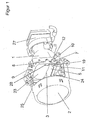
- FIGS. 1 and 2 illustrated headlight for vehicles is designed as a projection module, that an elliptical reflector 1, a arranged in the apex region of the reflector 1 light source 28, a lens 4th and a diaphragm shaft 5 arranged between the reflector 1 and the lens 2.
- the lens 2 is inserted into a table-shaped frame 25 which is fixed to the front edge region 8 of the reflector 1.
- the reflector 1 has an inner and outer focal point 2 and 3.
- the inner focal point, the light source 28 and the outer focal point 3, the middle upper portion of the diaphragm shaft 5 is assigned.
- the light source 28 is a high-pressure gas discharge lamp, which carries an ignition device 27 at its base.
- the diaphragm shaft 5 is made by die casting, for example, from a magnesium or aluminum alloy. It may also consist of an elongated hollow body made of sheet metal, wherein the contour of the lateral surface of the hollow body is produced by generating an internal high pressure (not shown). At its free end portions, the diaphragm shaft 5 each bearing means 10 with which the diaphragm shaft 5 is mounted on the front edge portion 8 of the reflector 1.
- the diaphragm shaft 5 is mounted perpendicular to the optical axis 6 of the headlight in the horizontal direction.
- One end section of the diaphragm shaft 5 is coupled to a motor (not shown) serving as drive means 20, by means of which the diaphragm shaft 5 can be brought into predetermined rotational positions.
- a control electronics for the motor is integrated in the drive means 20.
- the drive means 20 has a housing which is fastened to holding elements 21 of the reflector 1.
- the holding elements 21 are integrally formed on the reflector 1 lugs, where by means of screws or rivets, the drive means 20 on the reflector 1 can be fixed.
- the drive means 20 and thus the holding elements 21 are arranged between the front and rear side of the reflector 1.
- the reflector 1 has on two opposite sides holding elements 21, so that the drive means 20 is selectively attachable on both sides of the reflector 1.
- the lateral surfaces of the diaphragm shaft 5 is formed such that in different adjusted about the rotational axis 7 of the aperture shaft 5 rotational positions focal lines 8 of the optical light system are formed by means of which light-dark boundaries different dimmed light figures such as symmetric and asymmetric dipped beam for right and left be generated.
- the lateral surface of the diaphragm shaft 5 is formed curved at least in the region having the focal lines and has at least one surface portion extending two focal lines, which is formed differently from a cylindrical surface.
- the lateral surface of the diaphragm shaft 5 thus extends in the surface portion irregular (not shown).
- the lateral surface of the diaphragm shaft 5 has a flattening for high beam (not shown).
- a frame-like holder 9 is arranged, which abuts against the lens 4 side facing the front edge portion 8.
- the frame-like holder 9 is punched out of a sheet metal blank and has in the region of the diaphragm shaft 5 a shading device 24, which shields interfering light beams together with the diaphragm shaft 5.
- the shading 24 is designed in a strip shape and extends in its longitudinal extent parallel to the axis of rotation 7 of the diaphragm shaft 5.
- the axis of rotation 7 is defined by the support means 10 of the diaphragm shaft 5, which are the two free end portions of the diaphragm shaft 5.
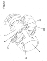
- both storage means 10 of the diaphragm shaft 5 of the first embodiment are shown.
- the two storage means 10 each have a bearing pin 16 whose central axis is the axis of rotation 7.
- the storage means 10, which is located farther away from the drive means 20, has a roller bearing 17 which is pushed onto the bearing pin 16 in a press fit.
- the rolling bearing 17 engages in a bearing shell 12 of the reflector 1 and is located on two positioning surfaces 13 of the bearing shell 12.
- the Positioning surfaces 13 are at an acute angle to each other and fix the diaphragm shaft very precisely to the reflection surface 23 of the reflector 1.
- the bearing shell 12 of the reflector 1 contact surfaces 15, which together with the positioning surfaces 13 a receiving groove for the Rolling 17 form.
- the contact surfaces 15 fix the diaphragm shaft 5 in its longitudinal extent.
- the bearing shell 12 of the reflector 1 and the reflection surface 23 of the reflector 1 are demolded together by a tool part.
- the rolling bearing 17 is held by a bearing shell 12 spanning portion 11 of the holder 9.
- the section 11 also forms a bearing shell 18, which together with the bearing shell 12 of the reflector 1 form a bearing opening for the roller bearing 17.
- the section 11 has a pressed out from its central region contact element 19 which bears under pretension with an abutment side 14 on the roller bearing 17 and forms a three-point system for the rolling bearing 17 together with the positioning surfaces 13.
- the diaphragm shaft 5 is mounted in the region of the drive means 20 with its bearing journal 16 axially floating in a bearing point of the drive means 20.
- the drive means 20 and the reflector 1 have intermeshing positioning means 22, by which the diaphragm shaft 5 is kept fixed exactly to the reflection surface 23 of the reflector 1.
- the positioning means 22 consist of pins of the drive means 20 which engage in corresponding holes of the reflector 1 without play.
- the plug-in direction of the positioning means 22 extends parallel to the axis of rotation 7 of the diaphragm shaft 5.
- the reflector 1 and the holder 9 have on the side of the drive means 20 and an unused bearing shell 12 and 18 on. As a result, and because the reflector also on the other side holding elements 21 and positioning means 22 for the drive means 20, the drive means 20 and the rolling bearing 17 can be selectively mounted on one or the other side of the reflector 1.
- both bearing means 10 of the diaphragm shaft 5 each have a roller bearing 17, which are held in a respective bearing shell 12 of the reflector 1 by the holder 9.
- the holding means 21 of the reflector 1 mounted drive means 20 is coupled via a gear 26 with the diaphragm shaft 5.
Landscapes
- Engineering & Computer Science (AREA)
- General Engineering & Computer Science (AREA)
- Non-Portable Lighting Devices Or Systems Thereof (AREA)
- Lighting Device Outwards From Vehicle And Optical Signal (AREA)
Claims (13)
- Projecteur pour véhicules avec un réflecteur (1) coulé en forme de coque qui présente un foyer intérieur et un foyer extérieur (2 et 3), avec un arbre d'enjoliveur (5) disposé entre une lentille (4) et le réflecteur (1), arbre qui peut être réglé en plusieurs positions rotatives pour différentes fonctions d'éclairage autour d'un axe rotatif (7) horizontal et perpendiculaire à l'axe optique (6), et avec un support (9) fixé sur le bord avant (8) du réflecteur (1) pour au moins un moyen de logement (10) de l'arbre d'enjoliveur (5), caractérisé en ce que le support (9) fixé sur le bord avant (8) du réflecteur (1) surmonte avec une section (11) une coque de logement (12) du bord avant (8) et que le moyen de logement (10) de l'arbre d'enjoliveur (5) est maintenu sans jeu radialement par rapport à l'axe rotatif (7) dans la coque de logement (12):
- Projecteur selon la revendication 1, caractérisé en ce que le réflecteur (1) moulé consiste en un métal léger moulé sous pression ou en de la matière plastique.
- Projecteur selon la revendication 1 ou 2, caractérisé en ce que la section (11) du support (9) surmontant la coque de logement (12) du réflecteur (1) repose sous précontrainte sur le moyen de logement (10) de l'arbre d'enjoliveur (5) et que le moyen de logement (10) vient comprimer la coque de logement (12).
- Projecteur selon l'une des revendications 1 à 3, caractérisé en ce que la coque du logement (12) du réflecteur (1) présente des surfaces de positionnement (13) définissant une installation à deux points pour le moyen de logement (10) de l'arbre d'enjoliveur (5).
- Projecteur selon la revendication 4, caractérisé en ce qu'un côté de l'installation (14) de la section (11) du support (9) surmontant la coque de logement (12) du réflecteur (1) avec les surfaces de positionnement (13) de la coque du logement (12) du réflecteur (1) définit une installation à trois points pour le moyen de logement (10) de l'arbre (5).
- Projecteur selon la revendication 4 ou 5, caractérisé en ce qu'une surface d'installation (15) fixant le moyen de logement (10) dans le sens de l'axe rotatif (7) est voisine d'au moins une des deux surfaces de positionnement (13) de l'installation à deux points.
- Projecteur selon l'une des revendications 1 à 6 ci-avant, caractérisé en ce que le moyen de logement (10) de l'arbre (5) présente un roulement (17) monté sur un tenon (16) de l'arbre (5)..
- Projecteur selon l'une des revendications 1 à 7, caractérisé en ce que le support (9) forme une coque de logement (18) qui, avec la coque de logement (12) du réflecteur (1), constitue une ouverture pour le moyen de logement (10) de l'arbre (5).
- Projecteur selon la revendication 8, caractérisé ence que la coque de logement (18) du support (9) présente un élément d'installation (19) radialement orienté vers l'intérieur et constituant le côté de l'installation (14) pour l'installation à trois points.
- Projecteur selon l'une des revendications 1 à 9, caractérisé en ce que l'arbre (5) avec un moyen de logement (10) est maintenu radialement et axialement sur une section d'extrémité par le support (9) et la coque de logement (12) du réflecteur (1) tandis que l'arbre (5) avec l'autre section d'extrémité libre est maintenu radialement par rapport à l'axe rotatif (7) dans un moyen d'entraînement (20) de l'arbre (5) fixé sur le réflecteur (1) et présentant un logement axial flottant.
- Projecteur selon la revendication 10, caractérisé en ce que le moyen d'entraînement (20) entre la face avant et la face arrière du réflecteur (1) est fixé sur un côté du réflecteur sur des éléments de maintien (21) du réflecteur (1), des moyens de positionnement (22) du réflecteur (1) et du moyen d'entraînement (20) étant emboîtés les uns dans les autres parallèlement à l'axe rotatif (7) de l'arbre (5), ces moyens de posi'ionnement positionnant le moyen d'entraînement (20) maintenant l'arbre (5) par rapport à la surface de réflexion (23) du réflecteur (1).
- Projecteur selon l'un des revendications 1 à 11, caractérisé en ce que le support (9) consiste en de la tôle qui entoure l'ouverture de sortie de la lumière du réflecteur (1), qui sert tant de support pour le projecteur que d'obscurcisseur (24), qui est voisin de l'arbre (5) et qui, au moins dans une position rotative de l'arbre (5) avec l'arbre (5) protège des rayons de lumière perturbateurs.
- Projecteur selon une ou plusieurs des revendications ci-avant, caractérisé ence que l'arbre est maintenu avec respectivement un moyen de logement disposé sur ses deux sections d'extrémité par le support dans une coque de logement du réflecteur, une section d'extrémité de l'arbre étant couplée avec un moyen d'entraînement disposé sur le réflecteur par une transmission.
Applications Claiming Priority (2)
| Application Number | Priority Date | Filing Date | Title |
|---|---|---|---|
| DE10340962 | 2003-09-05 | ||
| DE10340962A DE10340962A1 (de) | 2003-09-05 | 2003-09-05 | Scheinwerfer für Fahrzeuge |
Publications (3)
| Publication Number | Publication Date |
|---|---|
| EP1512904A2 EP1512904A2 (fr) | 2005-03-09 |
| EP1512904A3 EP1512904A3 (fr) | 2007-12-19 |
| EP1512904B1 true EP1512904B1 (fr) | 2010-01-20 |
Family
ID=34129661
Family Applications (1)
| Application Number | Title | Priority Date | Filing Date |
|---|---|---|---|
| EP04020697A Expired - Lifetime EP1512904B1 (fr) | 2003-09-05 | 2004-09-01 | Projecteur pour véhicules |
Country Status (3)
| Country | Link |
|---|---|
| EP (1) | EP1512904B1 (fr) |
| AT (1) | ATE456001T1 (fr) |
| DE (2) | DE10340962A1 (fr) |
Families Citing this family (2)
| Publication number | Priority date | Publication date | Assignee | Title |
|---|---|---|---|---|
| DE102005021705A1 (de) * | 2005-05-11 | 2006-11-16 | Hella Kgaa Hueck & Co. | Projektionsscheinwerfer für Fahrzeuge |
| DE102008047278A1 (de) * | 2008-09-16 | 2010-04-15 | Hella Kgaa Hueck & Co. | Scheinwerfer für Fahrzeuge und Herstellungsverfahren |
Family Cites Families (5)
| Publication number | Priority date | Publication date | Assignee | Title |
|---|---|---|---|---|
| US5373424A (en) * | 1992-10-21 | 1994-12-13 | Koito Manufacturing Co., Ltd. | Automotive projection headlamp |
| FR2721686B1 (fr) * | 1994-06-28 | 1996-09-13 | Valeo Vision | Projecteur du type elliptique, comportant un cache basculant. |
| DE19739089A1 (de) * | 1997-09-06 | 1999-03-11 | Hella Kg Hueck & Co | Scheinwerfer für Fahrzeuge |
| DE19921907A1 (de) * | 1999-05-12 | 2000-11-16 | Hella Kg Hueck & Co | Scheinwerfer für Fahrzeuge |
| DE10047207A1 (de) * | 2000-09-23 | 2002-04-11 | Hella Kg Hueck & Co | Scheinwerfer für Fahrzeuge |
-
2003
- 2003-09-05 DE DE10340962A patent/DE10340962A1/de not_active Withdrawn
-
2004
- 2004-09-01 DE DE502004010663T patent/DE502004010663D1/de not_active Expired - Lifetime
- 2004-09-01 AT AT04020697T patent/ATE456001T1/de not_active IP Right Cessation
- 2004-09-01 EP EP04020697A patent/EP1512904B1/fr not_active Expired - Lifetime
Also Published As
| Publication number | Publication date |
|---|---|
| EP1512904A2 (fr) | 2005-03-09 |
| ATE456001T1 (de) | 2010-02-15 |
| DE10340962A1 (de) | 2005-05-19 |
| EP1512904A3 (fr) | 2007-12-19 |
| DE502004010663D1 (de) | 2010-03-11 |
Similar Documents
| Publication | Publication Date | Title |
|---|---|---|
| DE3516813C2 (fr) | ||
| EP1660809B1 (fr) | Phare pour vehicules | |
| DE3827594C2 (fr) | ||
| DE4407108C2 (de) | Fahrzeugscheinwerfer mit einer verstellbaren Blendenanordnung | |
| EP1033528A2 (fr) | Projecteur pour véhicule | |
| EP0485832B1 (fr) | Ensemble projecteur pour véhicules | |
| DE3903631C1 (fr) | ||
| DE19546271B4 (de) | Scheinwerfer für Fahrzeuge mit einem verschwenkbaren Reflektor | |
| EP1512904B1 (fr) | Projecteur pour véhicules | |
| DE19602978B4 (de) | Fahrzeug-Scheinwerfer | |
| DE19805217B4 (de) | Kraftfahrzeugscheinwerfer mit einem Spiegel mit seitlich nebeneinander angeordneten Zonen und Verfahren zur Herstellung eines solchen Spiegels | |
| DE4421355C2 (de) | Verstellanordnung für einen Reflektor für einen Fahrzeugscheinwerfer | |
| EP1010935A2 (fr) | Projecteur por véhicules | |
| DE29909033U1 (de) | Beleuchtungseinrichtung für Fahrzeuge | |
| DE19749181A1 (de) | Scheinwerferanordnung | |
| EP0590454B1 (fr) | Projecteur pour véhicules | |
| EP0636831B1 (fr) | Ecran pour un phare non éblouissant de véhicule automobile | |
| DE3827593C2 (fr) | ||
| EP0985871A2 (fr) | Projecteur et procédé de fabrication de celui-ci | |
| DE3742191C2 (fr) | ||
| AT412992B (de) | Fahrzeugscheinwerfer | |
| DE1597934A1 (de) | Scheinwerfer,insbesondere fuer Kraftfahrzeuge | |
| DE10120216A1 (de) | Scheinwerfer für Fahrzeuge | |
| DE602005005111T2 (de) | Reflektor für eine Doppelstrahlentladungslampe hoher Intensität | |
| DE9218431U1 (de) | Abgeblendeter Scheinwerfer für Fahrzeuge |
Legal Events
| Date | Code | Title | Description |
|---|---|---|---|
| PUAI | Public reference made under article 153(3) epc to a published international application that has entered the european phase |
Free format text: ORIGINAL CODE: 0009012 |
|
| AK | Designated contracting states |
Kind code of ref document: A2 Designated state(s): AT BE BG CH CY CZ DE DK EE ES FI FR GB GR HU IE IT LI LU MC NL PL PT RO SE SI SK TR |
|
| AX | Request for extension of the european patent |
Extension state: AL HR LT LV MK |
|
| PUAL | Search report despatched |
Free format text: ORIGINAL CODE: 0009013 |
|
| AK | Designated contracting states |
Kind code of ref document: A3 Designated state(s): AT BE BG CH CY CZ DE DK EE ES FI FR GB GR HU IE IT LI LU MC NL PL PT RO SE SI SK TR |
|
| AX | Request for extension of the european patent |
Extension state: AL HR LT LV MK |
|
| RIC1 | Information provided on ipc code assigned before grant |
Ipc: F21W 101/10 20060101ALN20071109BHEP Ipc: F21V 14/08 20060101AFI20041102BHEP |
|
| 17P | Request for examination filed |
Effective date: 20080701 |
|
| AKX | Designation fees paid |
Designated state(s): AT BE BG CH CY CZ DE DK EE ES FI FR GB GR HU IE IT LI LU MC NL PL PT RO SE SI SK TR |
|
| GRAP | Despatch of communication of intention to grant a patent |
Free format text: ORIGINAL CODE: EPIDOSNIGR1 |
|
| GRAS | Grant fee paid |
Free format text: ORIGINAL CODE: EPIDOSNIGR3 |
|
| GRAA | (expected) grant |
Free format text: ORIGINAL CODE: 0009210 |
|
| AK | Designated contracting states |
Kind code of ref document: B1 Designated state(s): AT BE BG CH CY CZ DE DK EE ES FI FR GB GR HU IE IT LI LU MC NL PL PT RO SE SI SK TR |
|
| REG | Reference to a national code |
Ref country code: GB Ref legal event code: FG4D Free format text: NOT ENGLISH |
|
| REG | Reference to a national code |
Ref country code: CH Ref legal event code: EP |
|
| REG | Reference to a national code |
Ref country code: IE Ref legal event code: FG4D |
|
| REF | Corresponds to: |
Ref document number: 502004010663 Country of ref document: DE Date of ref document: 20100311 Kind code of ref document: P |
|
| REG | Reference to a national code |
Ref country code: NL Ref legal event code: VDEP Effective date: 20100120 |
|
| PG25 | Lapsed in a contracting state [announced via postgrant information from national office to epo] |
Ref country code: NL Free format text: LAPSE BECAUSE OF FAILURE TO SUBMIT A TRANSLATION OF THE DESCRIPTION OR TO PAY THE FEE WITHIN THE PRESCRIBED TIME-LIMIT Effective date: 20100120 Ref country code: PT Free format text: LAPSE BECAUSE OF FAILURE TO SUBMIT A TRANSLATION OF THE DESCRIPTION OR TO PAY THE FEE WITHIN THE PRESCRIBED TIME-LIMIT Effective date: 20100520 Ref country code: ES Free format text: LAPSE BECAUSE OF FAILURE TO SUBMIT A TRANSLATION OF THE DESCRIPTION OR TO PAY THE FEE WITHIN THE PRESCRIBED TIME-LIMIT Effective date: 20100501 |
|
| REG | Reference to a national code |
Ref country code: IE Ref legal event code: FD4D |
|
| PG25 | Lapsed in a contracting state [announced via postgrant information from national office to epo] |
Ref country code: FI Free format text: LAPSE BECAUSE OF FAILURE TO SUBMIT A TRANSLATION OF THE DESCRIPTION OR TO PAY THE FEE WITHIN THE PRESCRIBED TIME-LIMIT Effective date: 20100120 Ref country code: SI Free format text: LAPSE BECAUSE OF FAILURE TO SUBMIT A TRANSLATION OF THE DESCRIPTION OR TO PAY THE FEE WITHIN THE PRESCRIBED TIME-LIMIT Effective date: 20100120 Ref country code: PL Free format text: LAPSE BECAUSE OF FAILURE TO SUBMIT A TRANSLATION OF THE DESCRIPTION OR TO PAY THE FEE WITHIN THE PRESCRIBED TIME-LIMIT Effective date: 20100120 |
|
| PG25 | Lapsed in a contracting state [announced via postgrant information from national office to epo] |
Ref country code: SE Free format text: LAPSE BECAUSE OF FAILURE TO SUBMIT A TRANSLATION OF THE DESCRIPTION OR TO PAY THE FEE WITHIN THE PRESCRIBED TIME-LIMIT Effective date: 20100120 Ref country code: IE Free format text: LAPSE BECAUSE OF FAILURE TO SUBMIT A TRANSLATION OF THE DESCRIPTION OR TO PAY THE FEE WITHIN THE PRESCRIBED TIME-LIMIT Effective date: 20100120 Ref country code: CY Free format text: LAPSE BECAUSE OF FAILURE TO SUBMIT A TRANSLATION OF THE DESCRIPTION OR TO PAY THE FEE WITHIN THE PRESCRIBED TIME-LIMIT Effective date: 20100120 Ref country code: GR Free format text: LAPSE BECAUSE OF FAILURE TO SUBMIT A TRANSLATION OF THE DESCRIPTION OR TO PAY THE FEE WITHIN THE PRESCRIBED TIME-LIMIT Effective date: 20100421 Ref country code: EE Free format text: LAPSE BECAUSE OF FAILURE TO SUBMIT A TRANSLATION OF THE DESCRIPTION OR TO PAY THE FEE WITHIN THE PRESCRIBED TIME-LIMIT Effective date: 20100120 Ref country code: RO Free format text: LAPSE BECAUSE OF FAILURE TO SUBMIT A TRANSLATION OF THE DESCRIPTION OR TO PAY THE FEE WITHIN THE PRESCRIBED TIME-LIMIT Effective date: 20100120 |
|
| PLBE | No opposition filed within time limit |
Free format text: ORIGINAL CODE: 0009261 |
|
| STAA | Information on the status of an ep patent application or granted ep patent |
Free format text: STATUS: NO OPPOSITION FILED WITHIN TIME LIMIT |
|
| PG25 | Lapsed in a contracting state [announced via postgrant information from national office to epo] |
Ref country code: CZ Free format text: LAPSE BECAUSE OF FAILURE TO SUBMIT A TRANSLATION OF THE DESCRIPTION OR TO PAY THE FEE WITHIN THE PRESCRIBED TIME-LIMIT Effective date: 20100120 Ref country code: BG Free format text: LAPSE BECAUSE OF FAILURE TO SUBMIT A TRANSLATION OF THE DESCRIPTION OR TO PAY THE FEE WITHIN THE PRESCRIBED TIME-LIMIT Effective date: 20100420 Ref country code: SK Free format text: LAPSE BECAUSE OF FAILURE TO SUBMIT A TRANSLATION OF THE DESCRIPTION OR TO PAY THE FEE WITHIN THE PRESCRIBED TIME-LIMIT Effective date: 20100120 |
|
| 26N | No opposition filed |
Effective date: 20101021 |
|
| PG25 | Lapsed in a contracting state [announced via postgrant information from national office to epo] |
Ref country code: DK Free format text: LAPSE BECAUSE OF FAILURE TO SUBMIT A TRANSLATION OF THE DESCRIPTION OR TO PAY THE FEE WITHIN THE PRESCRIBED TIME-LIMIT Effective date: 20100120 |
|
| BERE | Be: lapsed |
Owner name: HELLA KGAA HUECK & CO. Effective date: 20100930 |
|
| PG25 | Lapsed in a contracting state [announced via postgrant information from national office to epo] |
Ref country code: IT Free format text: LAPSE BECAUSE OF FAILURE TO SUBMIT A TRANSLATION OF THE DESCRIPTION OR TO PAY THE FEE WITHIN THE PRESCRIBED TIME-LIMIT Effective date: 20100120 |
|
| PG25 | Lapsed in a contracting state [announced via postgrant information from national office to epo] |
Ref country code: MC Free format text: LAPSE BECAUSE OF NON-PAYMENT OF DUE FEES Effective date: 20100930 |
|
| REG | Reference to a national code |
Ref country code: CH Ref legal event code: PL |
|
| PG25 | Lapsed in a contracting state [announced via postgrant information from national office to epo] |
Ref country code: CH Free format text: LAPSE BECAUSE OF NON-PAYMENT OF DUE FEES Effective date: 20100930 Ref country code: LI Free format text: LAPSE BECAUSE OF NON-PAYMENT OF DUE FEES Effective date: 20100930 Ref country code: BE Free format text: LAPSE BECAUSE OF NON-PAYMENT OF DUE FEES Effective date: 20100930 |
|
| PG25 | Lapsed in a contracting state [announced via postgrant information from national office to epo] |
Ref country code: AT Free format text: LAPSE BECAUSE OF NON-PAYMENT OF DUE FEES Effective date: 20100901 |
|
| PG25 | Lapsed in a contracting state [announced via postgrant information from national office to epo] |
Ref country code: LU Free format text: LAPSE BECAUSE OF NON-PAYMENT OF DUE FEES Effective date: 20100901 Ref country code: HU Free format text: LAPSE BECAUSE OF FAILURE TO SUBMIT A TRANSLATION OF THE DESCRIPTION OR TO PAY THE FEE WITHIN THE PRESCRIBED TIME-LIMIT Effective date: 20100721 |
|
| PG25 | Lapsed in a contracting state [announced via postgrant information from national office to epo] |
Ref country code: TR Free format text: LAPSE BECAUSE OF FAILURE TO SUBMIT A TRANSLATION OF THE DESCRIPTION OR TO PAY THE FEE WITHIN THE PRESCRIBED TIME-LIMIT Effective date: 20100120 |
|
| REG | Reference to a national code |
Ref country code: FR Ref legal event code: PLFP Year of fee payment: 13 |
|
| REG | Reference to a national code |
Ref country code: FR Ref legal event code: PLFP Year of fee payment: 14 |
|
| PGFP | Annual fee paid to national office [announced via postgrant information from national office to epo] |
Ref country code: GB Payment date: 20170830 Year of fee payment: 14 |
|
| REG | Reference to a national code |
Ref country code: DE Ref legal event code: R081 Ref document number: 502004010663 Country of ref document: DE Owner name: HELLA GMBH CO. KGAA, DE Free format text: FORMER OWNER: HELLA KGAA HUECK CO., 59557 LIPPSTADT, DE Ref country code: DE Ref legal event code: R081 Ref document number: 502004010663 Country of ref document: DE Owner name: HELLA GMBH & CO. KGAA, DE Free format text: FORMER OWNER: HELLA KGAA HUECK & CO., 59557 LIPPSTADT, DE |
|
| REG | Reference to a national code |
Ref country code: FR Ref legal event code: PLFP Year of fee payment: 15 |
|
| GBPC | Gb: european patent ceased through non-payment of renewal fee |
Effective date: 20180901 |
|
| PG25 | Lapsed in a contracting state [announced via postgrant information from national office to epo] |
Ref country code: GB Free format text: LAPSE BECAUSE OF NON-PAYMENT OF DUE FEES Effective date: 20180901 |
|
| PGFP | Annual fee paid to national office [announced via postgrant information from national office to epo] |
Ref country code: FR Payment date: 20210714 Year of fee payment: 18 |
|
| PGFP | Annual fee paid to national office [announced via postgrant information from national office to epo] |
Ref country code: DE Payment date: 20210720 Year of fee payment: 18 |
|
| REG | Reference to a national code |
Ref country code: DE Ref legal event code: R119 Ref document number: 502004010663 Country of ref document: DE |
|
| PG25 | Lapsed in a contracting state [announced via postgrant information from national office to epo] |
Ref country code: FR Free format text: LAPSE BECAUSE OF NON-PAYMENT OF DUE FEES Effective date: 20220930 Ref country code: DE Free format text: LAPSE BECAUSE OF NON-PAYMENT OF DUE FEES Effective date: 20230401 |