EP1513421B1 - Paire de rouleaux pour tendre des bandes de matiere de filtre - Google Patents
Paire de rouleaux pour tendre des bandes de matiere de filtre Download PDFInfo
- Publication number
- EP1513421B1 EP1513421B1 EP03732427A EP03732427A EP1513421B1 EP 1513421 B1 EP1513421 B1 EP 1513421B1 EP 03732427 A EP03732427 A EP 03732427A EP 03732427 A EP03732427 A EP 03732427A EP 1513421 B1 EP1513421 B1 EP 1513421B1
- Authority
- EP
- European Patent Office
- Prior art keywords
- roller
- drive
- pair according
- roller pair
- shaft
- Prior art date
- Legal status (The legal status is an assumption and is not a legal conclusion. Google has not performed a legal analysis and makes no representation as to the accuracy of the status listed.)
- Expired - Lifetime
Links
Images

Classifications
-
- A—HUMAN NECESSITIES
- A24—TOBACCO; CIGARS; CIGARETTES; SIMULATED SMOKING DEVICES; SMOKERS' REQUISITES
- A24D—CIGARS; CIGARETTES; TOBACCO SMOKE FILTERS; MOUTHPIECES OF CIGARS OR CIGARETTES; MANUFACTURE OF TOBACCO SMOKE FILTERS OR MOUTHPIECES
- A24D3/00—Tobacco smoke filters, e.g. filter tips or filtering inserts; Filters specially adapted for simulated smoking devices; Mouthpieces of cigars or cigarettes
- A24D3/02—Manufacture of tobacco smoke filters
- A24D3/0204—Preliminary operations before the filter rod forming process, e.g. crimping, blooming
Definitions
- the invention relates to a roller pair for tensioning strands of filter material in the manufacture of cigarette filters according to the preamble of patent claim 1.
- the filter of filter cigarettes are usually made of a so-called filter tow of cellulose acetate. It is stripped from a bale of cellulose acetate and formed into a web or strand prior to being fed to the machine in which the filter plugs are made. The "cable" removed from the bale is heavily curled and is therefore subjected to tensile stress for expansion.
- two spaced-apart pairs of rollers are provided, of which the one which is driven in the transport direction from the lying at a greater speed than the rear, so as to generate a voltage.
- roller pairs used for this purpose are mounted on one end of the frame of the machine, one roller being made of metal and the other being a surface layer of elastic material, e.g. Having rubber or the like.
- Such arrangements are i.a. in DE 1 532 142 or DE 2 008 033.
- the overhead metal roller is driven, while the lower roller is mounted to run.
- the lower roller is pivotally mounted about a horizontal axis near its bearing.
- a linear pneumatic drive is provided to operate the pivoting.
- the invention has for its object to change roller pair of the specified type to the effect that the wear is reduced.
- the second roller of a drive via a second drive shaft and a propeller shaft is driven.
- the second drive shaft is coupled via a gear transmission with the first drive shaft. Therefore, an additional drive is not required.
- the second roller is also mounted so that the size of the gap between the rollers in adaptation to the thickness of the material over its length is variable.
- the contact pressure must be only so large that the acetate fibers between the spaced pairs of rollers can be held in order to stretch them in a certain ratio. In this way, the wear of the lining of the second roller is significantly reduced.
- the second roller is not only pivoted away from the first roller, but can also make a pivoting during operation within limits or undergo an adjustment parallel to itself, if this is expedient due to the thickness of the material.
- the resistance that must be overcome in such a movement of the second roller is that of the pivot drive, which therefore expediently acts on the second roller via a spring medium.
- the actuator in turn includes a pneumatic cylinder that automatically allows a limited pivoting of the roller.
- another actuator can act on the pivoting of the second roller via a spring medium.
- the second roller is coupled via a universal joint shaft to the second drive shaft.
- the second drive shaft may, as already mentioned, be the output shaft of a toothed wheel drive, whose input shaft represents the motor shaft.
- the second roller is hollow. Inside, a drive flange is fixed, which cooperates with a roller bearing, whose inner ring is mounted pivotably about a horizontal axis on a sleeve-shaped bearing component.
- the propeller shaft is passed through the sleeve-shaped component.
- the sleeve-shaped component is in turn pivotally mounted about a horizontal axis on the frame.
- the bearing component is pivotally mounted and can transmit this movement to the roller.
- the roller is in turn pivotally mounted on the bearing component, so that it is also adjustable parallel to itself in order to adapt to the thickness of the filter tow.
- the arrangement of the roller pair including the gear parts may be designed so that it can be attached to a conventional roller drive.
- the frame has a vertical support plate on which Flanged on one side of the drive motor, as it is known.
- a gear box for the gear transmission is mounted, which in turn allows the storage of the second roller.
- the rollers can be mounted together with the gear box and the gear housed therein as a unit to the conventional support plate.
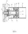
- a second drive can be provided for the second roller, which preferably runs with a torque which compensates for the bearing friction. The speed of the second drive is adjusted so that the peripheral speed of both rollers is equal, so that friction in the nip does not occur.
- the z. B. may be an air motor or a hydraulic motor, the contact pressure between the rollers can be reduced because the frictional forces of the bearings no longer need to be overcome.
- an overrunning clutch is provided according to an embodiment of the invention for the fast startup phase of the machine up to production speed. This allows the second roller to follow the first one. Under certain circumstances, it may be necessary to briefly increase the contact pressure during this startup time.
- the system described last provides a relatively resilient drive which can easily compensate for variations in speed and ensures that the upper and lower rollers move in lockstep.
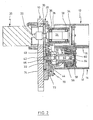
- a support plate 10 can be seen, which is part of a machine frame of a machine, which serves for the preparation of a so-called filter tow.
- a so-called filter tow To this plant belong two pairs of rolls, one of which is shown in FIGS. 1 to 3.
- the second pair may have the same structure or be conventional.
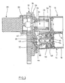
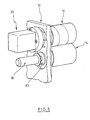
- FIGS. 1 to 3 an upper roller 12 and a lower roller 14 can be seen.
- the upper hollow roll is made of metal, while the lower roll 14 has a hollow metal shell 16 and a rubber coating 18.
- an electric motor 20 is flanged on the left side of the vertical support plate 10. Its drive shaft 22 is coupled via a coupling with a further shaft 24 which extends into a sleeve-shaped bearing body 26.
- the bearing body 26 is flanged to a transmission housing 28 which receives two spur gears 30, 32.
- the spur gear 30 is seated on the shaft 24 and meshes with the second spur gear 32.
- the gear ratio is 1: 1.
- the transmission housing 28 is fixedly connected to the support plate 10.
- the shaft 24 is rotatably connected to a flange 34, which in turn is clamped within the roller 32. A rotation of the shaft 24 thus leads to a corresponding rotation of the roller 12.
- the roller 12 is held centrally only at one point. The load is absorbed by the shaft 24, which is mounted by means of rolling bearings 36, 38 within the bearing body 26.
- a bearing flange 40 is connected by screw mounting, which rotatably supports a pin 46 by means of two roller bearings 42, 44, which is rotatably connected to the lower spur gear 32.
- a sleeve-shaped bearing component 50 is pivotally supported by the bearing flange 32. In FIGS. 1 to 3, this bearing takes place about a horizontal axis.
- the sleeve-shaped bearing member 50 by means of two diametrically opposed bearing journals 52, 54, the inner rings of two bearings 56, 58.
- the outer ring of the bearings 56, 58 is rotatably connected to the inside of the roller 14 ,
- a flange 60 is connected, with which the right end of a propeller shaft 62 is coupled torsionally rigid.
- the propeller shaft has a first universal joint 64 and a second universal joint 66, by means of which the latter an articulation takes place on the journal 46.
- the propeller shaft 62 extends through the interior of the sleeve-shaped bearing member 50. The interior of which is protected by a protective membrane 68 against ingress of dirt.
- an angular component 70 is screwed to the underside, which rests in Fig. 1 on a stop 72 which is connected to the transmission housing 28.
- a pneumatic Verstellzylinderan extract 74 is articulated on the lower leg of the component 70. With the help of Verstellzylinderan effet 74 can thus be pivoted upwardly the lower roller, as shown in Fig. 2.
- the pressure with which the two rollers 12, 14 are pressed against one another is predetermined by the pressure in the cylinder arrangement 74.
Landscapes
- Preliminary Treatment Of Fibers (AREA)
- Filtering Materials (AREA)
- Press Drives And Press Lines (AREA)
- Rollers For Roller Conveyors For Transfer (AREA)
- Details Of Cutting Devices (AREA)
- Metal Rolling (AREA)
- Manufacturing Of Cigar And Cigarette Tobacco (AREA)
- Shaping By String And By Release Of Stress In Plastics And The Like (AREA)
- Paper (AREA)
Claims (10)
- Paire de cylindres pour tendre des écheveaux de matériau de filtres lors de la fabrication de filtres de cigarettes, avec un premier cylindre en métal qui est entraîné en rotation par un dispositif d'entraînement et un deuxième cylindre dont la surface est constituée d'un matériau élastique, les deux cylindres étant montés d'un côté sur un châssis ou équivalent, et le deuxième cylindre étant monté de manière à pouvoir pivoter autour d'un axe horizontal perpendiculairement à son axe longitudinal en s'éloignant et en se rapprochant du premier cylindre, et avec un dispositif d'actionnement pour faire pivoter le deuxième cylindre, caractérisé en ce que le deuxième cylindre (14) peut être entraîné par un dispositif d'entraînement (20) par le biais d'un deuxième arbre d'entraînement (46) et d'un arbre articulé (62) et est monté de telle sorte que la taille de l'interstice entre les cylindres (12, 14) peut être modifiée sur sa longueur en fonction de l'épaisseur du matériau.
- Paire de cylindres selon la revendication 1, caractérisée en ce que le deuxième cylindre (14) est couplé au deuxième arbre d'entraînement (46) par un arbre à joint de cardan (62).
- Paire de cylindres selon la revendication 1 ou 2, caractérisée en ce que le deuxième arbre d'entraînement (42) est couplé au premier arbre d'entraînement (22) par une transmission par engrenage (30, 32).
- Paire de cylindres selon une des revendications 1 à 3, caractérisée en ce que le deuxième cylindre (14) est creux et présente à l'intérieur une bride d'entraînement (60) qui, au moyen d'un palier à rouleaux (56, 58), est montée de manière à pouvoir pivoter autour d'un axe horizontal au niveau d'un élément de palier (50) en forme de manchon par lequel l'arbre articulé (62) est guidé et qui, de son côté, est monté au niveau du châssis de manière à pouvoir pivoter sur un axe horizontal.
- Paire de cylindres selon la revendication 3 ou 4, caractérisée en ce que le châssis présente une plaque de support (10) verticale, sur une face de laquelle un moteur d'entraînement (20) est bridé, un boîtier de transmission (28) pour la transmission par engrenage étant monté sur l'autre face de la plaque de support (10) et le deuxième cylindre (14) étant monté sur la face extérieure du boîtier de transmission (28) de manière à pouvoir pivoter.
- Paire de cylindres selon une des revendications 3 à 5, caractérisée en ce que la transmission par engrenage présente deux roues à denture droite (30, 32).
- Paire de cylindres selon la revendication 1, caractérisée en ce que le deuxième cylindre (14) est entraîné par un deuxième dispositif d'entraînement séparé (80).
- Paire de cylindres selon la revendication 7, caractérisée en ce qu'un moteur hydraulique ou pneumatique (80) est prévu comme deuxième dispositif d'entraînement.
- Paire de cylindres selon la revendication 7 ou 8, caractérisée en ce que le deuxième dispositif d'entraînement (80) est couplé au deuxième cylindre (14) par l'intermédiaire d'un couplage à roue libre (82).
- Paire de cylindres selon une des revendications 7 à 9, caractérisée en ce que le deuxième dispositif d'entraînement (80) est entraîné avec un couple qui compense les pertes de friction des paliers.
Applications Claiming Priority (3)
| Application Number | Priority Date | Filing Date | Title |
|---|---|---|---|
| DE10227378A DE10227378B4 (de) | 2002-06-20 | 2002-06-20 | Walzenpaar zum Spannen von Strängen aus Filtermaterial |
| DE10227378 | 2002-06-20 | ||
| PCT/EP2003/005287 WO2004000046A1 (fr) | 2002-06-20 | 2003-05-20 | Paire de rouleaux pour tendre des bandes de matiere de filtre |
Publications (2)
| Publication Number | Publication Date |
|---|---|
| EP1513421A1 EP1513421A1 (fr) | 2005-03-16 |
| EP1513421B1 true EP1513421B1 (fr) | 2006-08-09 |
Family
ID=29719259
Family Applications (1)
| Application Number | Title | Priority Date | Filing Date |
|---|---|---|---|
| EP03732427A Expired - Lifetime EP1513421B1 (fr) | 2002-06-20 | 2003-05-20 | Paire de rouleaux pour tendre des bandes de matiere de filtre |
Country Status (7)
| Country | Link |
|---|---|
| US (1) | US7308735B2 (fr) |
| EP (1) | EP1513421B1 (fr) |
| AT (1) | ATE335413T1 (fr) |
| AU (1) | AU2003238363A1 (fr) |
| DE (2) | DE10227378B4 (fr) |
| ES (1) | ES2266824T3 (fr) |
| WO (1) | WO2004000046A1 (fr) |
Families Citing this family (7)
| Publication number | Priority date | Publication date | Assignee | Title |
|---|---|---|---|---|
| DE10354924B4 (de) * | 2003-11-25 | 2024-01-18 | Körber Technologies Gmbh | Vorrichtung zum Aufbereiten von Filtertowmaterial sowie Vorrichtung zur Herstellung von Filtern |
| ITBO20050603A1 (it) * | 2005-10-07 | 2007-04-08 | Cnh Italia Spa | Frizione a bagno d'olio |
| ITBO20060165A1 (it) * | 2006-03-08 | 2007-09-09 | Gd Spa | Macchina per la produzione di filtri di sigarette. |
| DE102006049823A1 (de) * | 2006-10-19 | 2008-04-24 | Hauni Maschinenbau Ag | Vorrichtung und Verfahren zur Aufbereitung von Filtermaterial für Zigarettenfilter oder dergleichen |
| CN103453118A (zh) * | 2013-08-30 | 2013-12-18 | 湖北中烟工业有限责任公司 | 一种双轴承过定位装置 |
| CN105852205A (zh) * | 2016-04-28 | 2016-08-17 | 宜兴市新建烟机配件有限公司 | 一种用于香烟过滤嘴开松机上聚氨酯橡胶辊 |
| CH712427A1 (de) * | 2016-05-02 | 2017-11-15 | Rieter Ag Maschf | Streckwerk einer Textilmaschine. |
Family Cites Families (14)
| Publication number | Priority date | Publication date | Assignee | Title |
|---|---|---|---|---|
| US2790208A (en) | 1954-03-15 | 1957-04-30 | Eastman Kodak Co | Method and means for opening crimped continuous filament tow |
| GB974512A (en) * | 1960-06-17 | 1964-11-04 | Eastman Kodak Co | An improved process and apparatus for the manufacture of uniformly crimped filamentary tow |
| DE1280114B (de) | 1963-04-19 | 1968-10-10 | Kurashiki Rayon Co | Vorrichtung zum Auflockern eines gekraeuselten, durchgehenden Faserstranges fuer Zigarettenfilter |
| GB1132984A (en) * | 1965-04-01 | 1968-11-06 | Courtaulds Ltd | Process and apparatus for opening tow |
| NL7002258A (fr) * | 1969-02-21 | 1970-08-25 | ||
| DE7016570U (de) * | 1970-05-02 | 1971-02-25 | Glanzstoff Ag | Verstellbares galettenabzugswerk. |
| CH557194A (de) * | 1972-10-28 | 1974-12-31 | Bellmer Geb Kg Maschf | Filterpresse. |
| US4759247A (en) * | 1987-10-22 | 1988-07-26 | Bernal Rotary Systems, Inc. | Rotary dies with adjustable cutter force |
| US5678774A (en) * | 1995-12-18 | 1997-10-21 | Etc. Industries Inc. | Fiberglass cutting apparatus and method |
| DE19712417A1 (de) * | 1997-03-25 | 1998-10-01 | Schaeffler Waelzlager Ohg | Andruckrolle für Textilmaschinen |
| DE10210357B4 (de) * | 2002-03-08 | 2005-12-22 | Voith Paper Patent Gmbh | Walzenanordnung |
| DE20309301U1 (de) * | 2003-06-13 | 2003-08-28 | Stowe Woodward AG, 33758 Schloß Holte-Stukenbrock | Breitstreckwalze |
| US7305739B2 (en) * | 2004-09-15 | 2007-12-11 | Celanese Acetate, Llc | Apparatus for tow opening |
| DE102005023992A1 (de) * | 2005-05-20 | 2006-11-23 | TRüTZSCHLER GMBH & CO. KG | Vorrichtung an einer Spinnereivorbereitungsmaschine, z.B. Karde, Krempel, Strecke, Kämmmaschine o.dgl., zum Ermitteln der Masse und/oder Masseschwankungen eines Fasermaterials, z.B. mindestens ein Faserband, Faservlies o.dgl., aus Baumwolle, Chemiefasern o. dgl. |
-
2002
- 2002-06-20 DE DE10227378A patent/DE10227378B4/de not_active Expired - Fee Related
-
2003
- 2003-05-20 AU AU2003238363A patent/AU2003238363A1/en not_active Abandoned
- 2003-05-20 US US10/518,130 patent/US7308735B2/en not_active Expired - Fee Related
- 2003-05-20 ES ES03732427T patent/ES2266824T3/es not_active Expired - Lifetime
- 2003-05-20 DE DE50304585T patent/DE50304585D1/de not_active Expired - Lifetime
- 2003-05-20 EP EP03732427A patent/EP1513421B1/fr not_active Expired - Lifetime
- 2003-05-20 AT AT03732427T patent/ATE335413T1/de active
- 2003-05-20 WO PCT/EP2003/005287 patent/WO2004000046A1/fr not_active Ceased
Also Published As
| Publication number | Publication date |
|---|---|
| ES2266824T3 (es) | 2007-03-01 |
| DE50304585D1 (de) | 2006-09-21 |
| WO2004000046A1 (fr) | 2003-12-31 |
| AU2003238363A1 (en) | 2004-01-06 |
| DE10227378B4 (de) | 2008-07-17 |
| DE10227378A1 (de) | 2004-01-08 |
| US20060179615A1 (en) | 2006-08-17 |
| EP1513421A1 (fr) | 2005-03-16 |
| US7308735B2 (en) | 2007-12-18 |
| ATE335413T1 (de) | 2006-09-15 |
Similar Documents
| Publication | Publication Date | Title |
|---|---|---|
| DE102006044610B4 (de) | Vorrichtung zum Schneiden und/oder Prägen eines Zuschnittes oder einer Materialbahn | |
| DE4440660A1 (de) | Trenneinrichtung zum Abtrennen perforierter Schlauchabschnitte | |
| DE4140876C2 (de) | Walzenpresse | |
| DE69214933T3 (de) | Rollenpresse | |
| EP2464256A1 (fr) | Dispositif de nettoyage d une surface fonctionnelle servant au guidage ou au traitement d une bande de matériau | |
| DD140655A5 (de) | Antrieb einer schaelmaschine fuer koernerfruechte | |
| EP1513421B1 (fr) | Paire de rouleaux pour tendre des bandes de matiere de filtre | |
| EP0324070A2 (fr) | Presse pour la fabrication continue de panneaux de fibres ou analogues | |
| DE2643017C3 (de) | Durchbiegungseinstellwalze für Papiermaschinen | |
| DE4019363C1 (en) | Roller drive for press - has torque supports connected directly on defined load lines | |
| DE19710530B4 (de) | Vorrichtung zur Erzeugung oder Weiterverarbeitung von Faserband | |
| CH687302A5 (de) | Längsschneideinrichtung für Bahnen. | |
| EP0232553A1 (fr) | Dispositif pour enrouler des objets plats arrivant en formation continue imbriqué | |
| DE202011107220U1 (de) | Drahtfördervorrichtung | |
| EP0775525A1 (fr) | Dispositif d'absorption de couple | |
| DE2643018C3 (de) | Walzenpresse mit einer Durchbiegungseinstellwalze z.B. für Papiermaschinen | |
| DE1527643A1 (de) | Walzwerksvorrichtung | |
| DE3318944C2 (de) | Faserbandablegeeinrichtung für eine Karde, Strecke o. dgl. | |
| DE69409556T2 (de) | Rotierende Schneidvorrichtung | |
| CH639145A5 (de) | Einrichtung an einer zettelmaschine, zum ein- und ausheben des zettelbaumes und zum zustellen und gleichfoermigen anpressen der presswalze. | |
| EP1151819B1 (fr) | Embrayage pour cisaille volante | |
| EP1740309A1 (fr) | Moulin a cylindres | |
| DE4019919C2 (de) | Warenabzugvorrichtung für Webmaschinen | |
| DE2845030C2 (de) | Rollgang zum Fördern von Walzgut | |
| DE69430821T2 (de) | Breitenveränderbare walze |
Legal Events
| Date | Code | Title | Description |
|---|---|---|---|
| PUAI | Public reference made under article 153(3) epc to a published international application that has entered the european phase |
Free format text: ORIGINAL CODE: 0009012 |
|
| 17P | Request for examination filed |
Effective date: 20041230 |
|
| AK | Designated contracting states |
Kind code of ref document: A1 Designated state(s): AT BE BG CH CY CZ DE DK EE ES FI FR GB GR HU IE IT LI LU MC NL PT RO SE SI SK TR |
|
| AX | Request for extension of the european patent |
Extension state: AL LT LV MK |
|
| DAX | Request for extension of the european patent (deleted) | ||
| GRAP | Despatch of communication of intention to grant a patent |
Free format text: ORIGINAL CODE: EPIDOSNIGR1 |
|
| GRAS | Grant fee paid |
Free format text: ORIGINAL CODE: EPIDOSNIGR3 |
|
| GRAA | (expected) grant |
Free format text: ORIGINAL CODE: 0009210 |
|
| AK | Designated contracting states |
Kind code of ref document: B1 Designated state(s): AT BE BG CH CY CZ DE DK EE ES FI FR GB GR HU IE IT LI LU MC NL PT RO SE SI SK TR |
|
| PG25 | Lapsed in a contracting state [announced via postgrant information from national office to epo] |
Ref country code: IT Free format text: LAPSE BECAUSE OF FAILURE TO SUBMIT A TRANSLATION OF THE DESCRIPTION OR TO PAY THE FEE WITHIN THE PRESCRIBED TIME-LIMIT;WARNING: LAPSES OF ITALIAN PATENTS WITH EFFECTIVE DATE BEFORE 2007 MAY HAVE OCCURRED AT ANY TIME BEFORE 2007. THE CORRECT EFFECTIVE DATE MAY BE DIFFERENT FROM THE ONE RECORDED. Effective date: 20060809 Ref country code: CZ Free format text: LAPSE BECAUSE OF FAILURE TO SUBMIT A TRANSLATION OF THE DESCRIPTION OR TO PAY THE FEE WITHIN THE PRESCRIBED TIME-LIMIT Effective date: 20060809 Ref country code: SK Free format text: LAPSE BECAUSE OF FAILURE TO SUBMIT A TRANSLATION OF THE DESCRIPTION OR TO PAY THE FEE WITHIN THE PRESCRIBED TIME-LIMIT Effective date: 20060809 Ref country code: IE Free format text: LAPSE BECAUSE OF FAILURE TO SUBMIT A TRANSLATION OF THE DESCRIPTION OR TO PAY THE FEE WITHIN THE PRESCRIBED TIME-LIMIT Effective date: 20060809 Ref country code: FI Free format text: LAPSE BECAUSE OF FAILURE TO SUBMIT A TRANSLATION OF THE DESCRIPTION OR TO PAY THE FEE WITHIN THE PRESCRIBED TIME-LIMIT Effective date: 20060809 Ref country code: SI Free format text: LAPSE BECAUSE OF FAILURE TO SUBMIT A TRANSLATION OF THE DESCRIPTION OR TO PAY THE FEE WITHIN THE PRESCRIBED TIME-LIMIT Effective date: 20060809 Ref country code: RO Free format text: LAPSE BECAUSE OF FAILURE TO SUBMIT A TRANSLATION OF THE DESCRIPTION OR TO PAY THE FEE WITHIN THE PRESCRIBED TIME-LIMIT Effective date: 20060809 |
|
| REG | Reference to a national code |
Ref country code: GB Ref legal event code: FG4D Free format text: NOT ENGLISH |
|
| REG | Reference to a national code |
Ref country code: CH Ref legal event code: EP |
|
| REG | Reference to a national code |
Ref country code: IE Ref legal event code: FG4D Free format text: LANGUAGE OF EP DOCUMENT: GERMAN |
|
| REF | Corresponds to: |
Ref document number: 50304585 Country of ref document: DE Date of ref document: 20060921 Kind code of ref document: P |
|
| GBT | Gb: translation of ep patent filed (gb section 77(6)(a)/1977) |
Effective date: 20060913 |
|
| PG25 | Lapsed in a contracting state [announced via postgrant information from national office to epo] |
Ref country code: DK Free format text: LAPSE BECAUSE OF FAILURE TO SUBMIT A TRANSLATION OF THE DESCRIPTION OR TO PAY THE FEE WITHIN THE PRESCRIBED TIME-LIMIT Effective date: 20061109 Ref country code: BG Free format text: LAPSE BECAUSE OF FAILURE TO SUBMIT A TRANSLATION OF THE DESCRIPTION OR TO PAY THE FEE WITHIN THE PRESCRIBED TIME-LIMIT Effective date: 20061109 Ref country code: SE Free format text: LAPSE BECAUSE OF FAILURE TO SUBMIT A TRANSLATION OF THE DESCRIPTION OR TO PAY THE FEE WITHIN THE PRESCRIBED TIME-LIMIT Effective date: 20061109 |
|
| PG25 | Lapsed in a contracting state [announced via postgrant information from national office to epo] |
Ref country code: PT Free format text: LAPSE BECAUSE OF FAILURE TO SUBMIT A TRANSLATION OF THE DESCRIPTION OR TO PAY THE FEE WITHIN THE PRESCRIBED TIME-LIMIT Effective date: 20070109 |
|
| REG | Reference to a national code |
Ref country code: ES Ref legal event code: FG2A Ref document number: 2266824 Country of ref document: ES Kind code of ref document: T3 |
|
| ET | Fr: translation filed | ||
| REG | Reference to a national code |
Ref country code: IE Ref legal event code: FD4D |
|
| PLBE | No opposition filed within time limit |
Free format text: ORIGINAL CODE: 0009261 |
|
| STAA | Information on the status of an ep patent application or granted ep patent |
Free format text: STATUS: NO OPPOSITION FILED WITHIN TIME LIMIT |
|
| 26N | No opposition filed |
Effective date: 20070510 |
|
| REG | Reference to a national code |
Ref country code: CH Ref legal event code: PL |
|
| PG25 | Lapsed in a contracting state [announced via postgrant information from national office to epo] |
Ref country code: MC Free format text: LAPSE BECAUSE OF NON-PAYMENT OF DUE FEES Effective date: 20070531 |
|
| PG25 | Lapsed in a contracting state [announced via postgrant information from national office to epo] |
Ref country code: CH Free format text: LAPSE BECAUSE OF NON-PAYMENT OF DUE FEES Effective date: 20070531 Ref country code: LI Free format text: LAPSE BECAUSE OF NON-PAYMENT OF DUE FEES Effective date: 20070531 |
|
| PG25 | Lapsed in a contracting state [announced via postgrant information from national office to epo] |
Ref country code: GR Free format text: LAPSE BECAUSE OF FAILURE TO SUBMIT A TRANSLATION OF THE DESCRIPTION OR TO PAY THE FEE WITHIN THE PRESCRIBED TIME-LIMIT Effective date: 20061110 |
|
| PG25 | Lapsed in a contracting state [announced via postgrant information from national office to epo] |
Ref country code: EE Free format text: LAPSE BECAUSE OF FAILURE TO SUBMIT A TRANSLATION OF THE DESCRIPTION OR TO PAY THE FEE WITHIN THE PRESCRIBED TIME-LIMIT Effective date: 20060809 |
|
| PGFP | Annual fee paid to national office [announced via postgrant information from national office to epo] |
Ref country code: BE Payment date: 20090310 Year of fee payment: 7 |
|
| PG25 | Lapsed in a contracting state [announced via postgrant information from national office to epo] |
Ref country code: LU Free format text: LAPSE BECAUSE OF NON-PAYMENT OF DUE FEES Effective date: 20070520 Ref country code: CY Free format text: LAPSE BECAUSE OF FAILURE TO SUBMIT A TRANSLATION OF THE DESCRIPTION OR TO PAY THE FEE WITHIN THE PRESCRIBED TIME-LIMIT Effective date: 20060809 |
|
| PG25 | Lapsed in a contracting state [announced via postgrant information from national office to epo] |
Ref country code: TR Free format text: LAPSE BECAUSE OF FAILURE TO SUBMIT A TRANSLATION OF THE DESCRIPTION OR TO PAY THE FEE WITHIN THE PRESCRIBED TIME-LIMIT Effective date: 20060809 Ref country code: HU Free format text: LAPSE BECAUSE OF FAILURE TO SUBMIT A TRANSLATION OF THE DESCRIPTION OR TO PAY THE FEE WITHIN THE PRESCRIBED TIME-LIMIT Effective date: 20070210 |
|
| BERE | Be: lapsed |
Owner name: *INTERNATIONAL TOBACCO MACHINERY B.V. Effective date: 20100531 |
|
| PG25 | Lapsed in a contracting state [announced via postgrant information from national office to epo] |
Ref country code: BE Free format text: LAPSE BECAUSE OF NON-PAYMENT OF DUE FEES Effective date: 20100531 |
|
| PGFP | Annual fee paid to national office [announced via postgrant information from national office to epo] |
Ref country code: GB Payment date: 20140520 Year of fee payment: 12 |
|
| PGFP | Annual fee paid to national office [announced via postgrant information from national office to epo] |
Ref country code: ES Payment date: 20140521 Year of fee payment: 12 Ref country code: NL Payment date: 20140520 Year of fee payment: 12 Ref country code: AT Payment date: 20140519 Year of fee payment: 12 Ref country code: FR Payment date: 20140516 Year of fee payment: 12 Ref country code: IT Payment date: 20140528 Year of fee payment: 12 |
|
| PGFP | Annual fee paid to national office [announced via postgrant information from national office to epo] |
Ref country code: DE Payment date: 20140708 Year of fee payment: 12 |
|
| REG | Reference to a national code |
Ref country code: DE Ref legal event code: R119 Ref document number: 50304585 Country of ref document: DE |
|
| REG | Reference to a national code |
Ref country code: AT Ref legal event code: MM01 Ref document number: 335413 Country of ref document: AT Kind code of ref document: T Effective date: 20150520 |
|
| GBPC | Gb: european patent ceased through non-payment of renewal fee |
Effective date: 20150520 |
|
| PG25 | Lapsed in a contracting state [announced via postgrant information from national office to epo] |
Ref country code: IT Free format text: LAPSE BECAUSE OF NON-PAYMENT OF DUE FEES Effective date: 20150520 |
|
| REG | Reference to a national code |
Ref country code: NL Ref legal event code: MM Effective date: 20150601 |
|
| REG | Reference to a national code |
Ref country code: FR Ref legal event code: ST Effective date: 20160129 |
|
| PG25 | Lapsed in a contracting state [announced via postgrant information from national office to epo] |
Ref country code: AT Free format text: LAPSE BECAUSE OF NON-PAYMENT OF DUE FEES Effective date: 20150520 |
|
| PG25 | Lapsed in a contracting state [announced via postgrant information from national office to epo] |
Ref country code: NL Free format text: LAPSE BECAUSE OF NON-PAYMENT OF DUE FEES Effective date: 20150601 Ref country code: GB Free format text: LAPSE BECAUSE OF NON-PAYMENT OF DUE FEES Effective date: 20150520 Ref country code: DE Free format text: LAPSE BECAUSE OF NON-PAYMENT OF DUE FEES Effective date: 20151201 |
|
| PG25 | Lapsed in a contracting state [announced via postgrant information from national office to epo] |
Ref country code: FR Free format text: LAPSE BECAUSE OF NON-PAYMENT OF DUE FEES Effective date: 20150601 |
|
| REG | Reference to a national code |
Ref country code: ES Ref legal event code: FD2A Effective date: 20160629 |
|
| PG25 | Lapsed in a contracting state [announced via postgrant information from national office to epo] |
Ref country code: ES Free format text: LAPSE BECAUSE OF NON-PAYMENT OF DUE FEES Effective date: 20150521 |