EP1514012B1 - Separateur d'huile centrifuge utilise dans un carter de vilebrequin d'un moteur a combustion interne - Google Patents
Separateur d'huile centrifuge utilise dans un carter de vilebrequin d'un moteur a combustion interne Download PDFInfo
- Publication number
- EP1514012B1 EP1514012B1 EP03722543A EP03722543A EP1514012B1 EP 1514012 B1 EP1514012 B1 EP 1514012B1 EP 03722543 A EP03722543 A EP 03722543A EP 03722543 A EP03722543 A EP 03722543A EP 1514012 B1 EP1514012 B1 EP 1514012B1
- Authority
- EP
- European Patent Office
- Prior art keywords
- centrifuge
- oil separator
- shaft
- centrifugal oil
- housing
- Prior art date
- Legal status (The legal status is an assumption and is not a legal conclusion. Google has not performed a legal analysis and makes no representation as to the accuracy of the status listed.)
- Expired - Lifetime
Links
- 238000002485 combustion reaction Methods 0.000 title claims description 10
- 239000002184 metal Substances 0.000 claims description 19
- 238000007599 discharging Methods 0.000 claims description 5
- 239000000203 mixture Substances 0.000 description 4
- 239000002245 particle Substances 0.000 description 3
- 238000000926 separation method Methods 0.000 description 3
- 230000008021 deposition Effects 0.000 description 2
- 238000011161 development Methods 0.000 description 2
- 230000018109 developmental process Effects 0.000 description 2
- 238000009434 installation Methods 0.000 description 2
- 238000007789 sealing Methods 0.000 description 2
- 230000001419 dependent effect Effects 0.000 description 1
- 230000002093 peripheral effect Effects 0.000 description 1
- 238000007142 ring opening reaction Methods 0.000 description 1
Images

Classifications
-
- F—MECHANICAL ENGINEERING; LIGHTING; HEATING; WEAPONS; BLASTING
- F01—MACHINES OR ENGINES IN GENERAL; ENGINE PLANTS IN GENERAL; STEAM ENGINES
- F01M—LUBRICATING OF MACHINES OR ENGINES IN GENERAL; LUBRICATING INTERNAL COMBUSTION ENGINES; CRANKCASE VENTILATING
- F01M13/00—Crankcase ventilating or breathing
- F01M13/04—Crankcase ventilating or breathing having means for purifying air before leaving crankcase, e.g. removing oil
- F01M2013/0422—Separating oil and gas with a centrifuge device
Definitions
- the invention relates to a centrifugal oil separator in a crankcase of an internal combustion engine according to the preamble of claim 1.
- centrifugal oil separator Such a centrifugal oil separator is described in the document DE 196 07 919 A1.
- oil particles can be deposited in an oil-air mixture in a crankcase of an internal combustion engine and returned to the oil sump.
- the centrifugal oil separator uses the principle here of separating and discharging the oil particles by means of centrifugal forces by means of rotation.
- the oil separator has a centrifuge housing with a separating chamber therein, in which baffles are arranged, on which the oil particles can accumulate. The collected oil is discharged radially, the cleaned air is discharged axially via a discharge channel in the centrifuge shaft.
- centrifuge housing is usually flanged and screwed in the known oil separators on a shaft driven by the internal combustion engine.
- the invention is based on the problem of improving the ease of assembly of centrifugal oil separators. In addition, a good rotational ability and long life of the oil separator should be ensured.
- the centrifugal oil separator according to the invention has a centrifuge housing made of plastic, in which a metal bush is integrated, which is pushed onto the centrifuge shaft.
- the centrifuge housing and the metal bushing form a prefabricated unit which is to be pushed onto the shaft and connected to it.
- the metal bushing is able to transmit high holding forces, so that a secure attachment to the centrifuge shaft is possible.
- the plastic centrifuge housing is characterized by a low weight, which in particular also results in lower centrifugal forces in the housing wall during rotation of the oil separator.
- the metal bushing can be pushed with a small clearance on the centrifuge shaft; During operation, game-related forces are readily absorbed by the metal bushing, relieving the centrifuge housing of these forces, thereby providing improved rotational capability and longer life.
- the centrifuge shaft is designed as a separate component which is non-rotatably connected to a rotating shaft of the internal combustion engine - for example, the camshaft, the crankshaft or a balance shaft - is connected.
- the centrifugal oil separator with the separate centrifuge shaft form a preassembled unit which is prefabricated used in the internal combustion engine and connected thereto. It has proven to be expedient to connect the oil separator with a sprocket, wherein the centrifuge shaft is inserted into a recess in the sprocket, in particular as an interference fit is inserted into the recess. Additional connection measures between the oil separator and the shaft can therefore be dispensed with in principle.
- an air guiding space can be enclosed in particular air-tight and pressure-tight, which serves for discharging the clean air after the deposition of the oil.
- the air guide space advantageously encloses annularly the centrifuge shaft, which communicates via radial openings with the air guide space, through which the clean air can escape radially inwardly into an axially extending flow channel in the centrifuge shaft. The clean air can be removed from the oil separator via the axial flow channel.
- metal bushing is injected into the impeller.
- a locking ring may be mounted on the shaft.
- a nut into consideration, which is screwed onto the metal bushing.
- centrifugal oil separator 1 is rotatably connected to a camshaft 2 of an internal combustion engine and is seated on an end face of a sprocket 3, which is flanged frontally to the camshaft 2 and fixedly coupled thereto.
- the oil separator 1 comprises a centrifuge housing 4, which is made of plastic, and a metal bushing 5, which is integrated in the centrifuge housing 4 and forms the hub of the centrifuge housing.
- the oil separator 1 comprises a centrifuge shaft 6, on which the metal bush 5 is pushed.
- the metal bush 5 is secured both in the circumferential direction and axially against unintentional release of the centrifuge shaft 6.
- a locking ring 8 is provided, which is insertable into a circumferential groove on the centrifuge shaft 6 and in turn is secured against axial loss.
- the centrifuge shaft 6 is designed as a separate, independent of the camshaft 2 component.
- the centrifuge shaft 6 is inserted into an axial recess in the sprocket 3, in particular pushed under pressure, optionally also additional or alternative fastening measures come into consideration.
- the oil separator 1 On the side facing away from the sprocket 3, the oil separator 1 has a ⁇ labscheiderdeckel 7, which is also seated on the centrifuge shaft 6.
- the oil separator lid 7 also forms part of the oil separator 1 and, like the centrifuge housing 4, the metal bushing 5 and the centrifuge shaft 6 can be assembled into a prefabricated unit.
- a separation chamber 10 is formed, which circulates annularly around the metal bushing 5 and in which the radially according to arrow 11 flowing into the housing air-oil mixture is separated into its components oil and air.
- the inflow of the air-oil mixture via a radial inflow channel 12, which is formed between an end face of the centrifuge housing 4 and the oil separator lid 7.
- baffles 13 may be located to assist the deposition of the oil.
- the separated oil is discharged radially according to arrow 14 through outflow openings 15 in the peripheral wall of the centrifuge housing 4.
- the clean air leaves the separation chamber 10 via axial outflow openings 16 in a side wall of the centrifuge housing 4 facing the sprocket 3 and initially flows into an annular air guidance space 18, which is located in a End face of the sprocket 3 is located and is bounded axially by a wall side of the centrifuge housing 4 and radially inwardly of the centrifuge shaft 6.
- the air guide chamber 18 is in particular sealed air-tight and pressure-tight relative to the environment. To assist the sealing a sealing ring 19 between the centrifuge housing 4 and sprocket 3 is provided.
- the centrifuge shaft 6 annularly enclosing air duct 18 communicates via radial bores 20 in the wall of the centrifuge shaft 6 with an axially extending flow channel 21 in the interior of the centrifuge shaft.
- the clean air is guided from the air guide chamber 18 in the direction of arrow 17 to the radial bores 20 and further through this radially inwardly and axially via the flow channel 21 in the direction of arrow 22 from the oil separator 1.
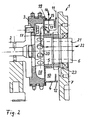
- the structure of the oil separator 1 of FIG. 2 corresponds in principle to that of the previous embodiment, but with the difference that for the axial securing of metal bushing 5 and centrifuge housing 4 on the centrifuge shaft 6, a nut 23 is screwed onto the shaft 6.
Landscapes
- Engineering & Computer Science (AREA)
- Mechanical Engineering (AREA)
- General Engineering & Computer Science (AREA)
- Lubrication Details And Ventilation Of Internal Combustion Engines (AREA)
- Centrifugal Separators (AREA)
Claims (10)
- Séparateur d'huile centrifuge dans un carter de vilebrequin d'un moteur à combustion interne, avec un carter de centrifugeuse posé de façon solidaire en rotation sur un arbre de centrifugeuse (6) rotatif, caractérisé en ce que le carter de centrifugeuse (4) est fabriqué à base de matière synthétique et un manchon métallique (5), qui est enfilé sur l'arbre de centrifugeuse (6), est intégré dans le carter de centrifugeuse (4).
- Séparateur d'huile centrifuge selon la revendication 1, caractérisé en ce que, l'arbre de centrifugeuse (6) est réalisé comme un composant séparé, qui est relié de façon solidaire en rotation à un arbre (2) rotatif du moteur à combustion interne.
- Séparateur d'huile centrifuge selon la revendication 2, caractérisé en ce que, le carter de centrifugeuse (4) est contigu axialement à une roue à chaîne (3) qui tourne avec l'arbre (2).
- Séparateur d'huile centrifuge selon la revendication 3, caractérisé en ce que, un espace de guidage d'air (18) pour la déviation d'air pur est formé entre un côté de paroi du carter de centrifugeuse (4) et la roue à chaîne (3) .
- Séparateur d'huile centrifuge selon les revendications 2 et 3, caractérisé en ce que, l'arbre de centrifugeuse (6) est inséré dans un évidemment dans la roue à chaîne (3).
- Séparateur d'huile centrifuge selon l'une des revendications 1 à 5, caractérisé en ce que, l'arbre de centrifugeuse (6) présente des alésages radiaux pour la déviation de l'air pur.
- Séparateur d'huile centrifuge selon l'une des revendications 1 à 6, caractérisé en ce que, l'arbre de centrifugeuse (6) présente un canal d'écoulement (21) axial pour la déviation d'air pur.
- Séparateur d'huile centrifuge selon l'une des revendications 1 à 7, caractérisé en ce que, la douille métallique (5) est injectée dans le carter de centrifugeuse (4).
- Séparateur d'huile centrifuge selon l'une des revendications 1 à 8, caractérisé en ce que, une bague de sûreté (8) repose sur l'arbre de centrifugeuse (6) pour le blocage axial de la douille métallique (5).
- Séparateur d'huile centrifuge selon l'une des revendications 1 à 9, caractérisé en ce que, un écrou rainuré (23) est vissé sur l'arbre de centrifugeuse (6) pour le blocage axial.
Applications Claiming Priority (3)
| Application Number | Priority Date | Filing Date | Title |
|---|---|---|---|
| DE10226695 | 2002-06-15 | ||
| DE10226695A DE10226695A1 (de) | 2002-06-15 | 2002-06-15 | Zentrifugal-Ölabscheider in einem Kurbelgehäuse einer Brennkraftmaschine |
| PCT/EP2003/004308 WO2003106821A1 (fr) | 2002-06-15 | 2003-04-25 | Separateur d'huile centrifuge utilise dans un carter de vilebrequin d'un moteur a combustion interne |
Publications (2)
| Publication Number | Publication Date |
|---|---|
| EP1514012A1 EP1514012A1 (fr) | 2005-03-16 |
| EP1514012B1 true EP1514012B1 (fr) | 2006-02-01 |
Family
ID=29594545
Family Applications (1)
| Application Number | Title | Priority Date | Filing Date |
|---|---|---|---|
| EP03722543A Expired - Lifetime EP1514012B1 (fr) | 2002-06-15 | 2003-04-25 | Separateur d'huile centrifuge utilise dans un carter de vilebrequin d'un moteur a combustion interne |
Country Status (5)
| Country | Link |
|---|---|
| US (1) | US7309308B2 (fr) |
| EP (1) | EP1514012B1 (fr) |
| JP (1) | JP4048297B2 (fr) |
| DE (2) | DE10226695A1 (fr) |
| WO (1) | WO2003106821A1 (fr) |
Families Citing this family (24)
| Publication number | Priority date | Publication date | Assignee | Title |
|---|---|---|---|---|
| DE502006007644D1 (de) | 2005-05-10 | 2010-09-23 | Mahle Int Gmbh | In eine axial hohle welle eines verbrennungsmotors integrierte zentrifugal-ölnebelabscheidereinrichtung |
| DE102005034273A1 (de) * | 2005-07-22 | 2006-06-14 | Daimlerchrysler Ag | Brennkraftmaschine |
| US7455057B2 (en) * | 2005-11-14 | 2008-11-25 | Brp-Rotax Gmbh & Co. Kg | Internal combustion engine blow-by gas ventilation system |
| DE102006012611A1 (de) | 2006-03-20 | 2007-09-27 | Mahle International Gmbh | Zylinderkopf eines Verbrennungsmotors |
| US7959546B2 (en) | 2007-01-24 | 2011-06-14 | Honeywell International Inc. | Oil centrifuge for extracting particulates from a continuous flow of fluid |
| US8166958B2 (en) * | 2007-08-15 | 2012-05-01 | GM Global Technology Operations LLC | Positive crankcase ventilation system for an internal combustion engine |
| DE102008028173A1 (de) | 2008-06-12 | 2009-01-22 | Daimler Ag | Zentrifugal-Ölabscheider |
| DE202008014734U1 (de) * | 2008-11-06 | 2010-03-25 | Hengst Gmbh & Co.Kg | Zentrifugalabscheider |
| DE102009012402A1 (de) * | 2009-03-10 | 2010-09-23 | Thyssenkrupp Presta Teccenter Ag | Wellenkörper mit integrierter Ölabscheideeinrichtung |
| SE534773C2 (sv) * | 2010-04-09 | 2011-12-13 | Alfa Laval Corp Ab | Centrifugalseparator anordnad inuti en förbränningsmotor |
| JP5724357B2 (ja) * | 2010-12-16 | 2015-05-27 | スズキ株式会社 | エンジンのブリーザ装置 |
| US8657931B2 (en) | 2011-08-17 | 2014-02-25 | Hamilton Sundstrand Corporation | Gearbox deoiler with sychnronizer |
| JP5867051B2 (ja) * | 2011-12-14 | 2016-02-24 | アイシン精機株式会社 | オイル分離装置 |
| JP6102468B2 (ja) * | 2013-04-25 | 2017-03-29 | スズキ株式会社 | エンジンのブリーザ構造 |
| JP6135488B2 (ja) * | 2013-12-12 | 2017-05-31 | スズキ株式会社 | エンジンのブリーザ装置 |
| EP2977573B1 (fr) * | 2014-07-24 | 2017-05-10 | Fiat Group Automobiles S.p.A. | Moteur à combustion interne avec un système de recirculation de gaz de carter à séparation à deux étages |
| US9709602B2 (en) * | 2015-04-09 | 2017-07-18 | Fisher-Rosemount Systems, Inc. | Method for supplying fieldbus communication and power from a handheld maintenance tool in a hazardous area using a single lead set |
| US10473206B2 (en) * | 2015-07-02 | 2019-11-12 | Deere & Company | Transmission vent |
| GB2555557A (en) | 2016-05-10 | 2018-05-09 | Continental automotive systems inc | Oil separator for reducing residue deposits |
| DE102016008299B4 (de) * | 2016-07-06 | 2020-12-31 | Neander Motors Ag | Ölabscheideeinrichtung für eine Brennkraftmaschine |
| US20180085699A1 (en) * | 2016-09-29 | 2018-03-29 | Corneliu Birtok-Baneasa | Air filter for internal combustion engines |
| US11466602B2 (en) | 2016-12-02 | 2022-10-11 | Arctic Cat Inc. | Breather shaft |
| US11097285B2 (en) | 2018-01-11 | 2021-08-24 | Kuhn Performance Technologies, Llc | Crankcase ventilation management devices, systems, and methods |
| JP2024093623A (ja) * | 2022-12-27 | 2024-07-09 | 本田技研工業株式会社 | 過給式内燃機関 |
Family Cites Families (10)
| Publication number | Priority date | Publication date | Assignee | Title |
|---|---|---|---|---|
| GB709646A (en) * | 1951-07-12 | 1954-06-02 | Rolls Royce | Improvements in or relating to oil separator means for engine breather arrangements |
| NL8501767A (nl) * | 1985-06-19 | 1987-01-16 | Euro Technical Oilservices Bv | Inrichting voor het behandelen van een verontreinigingen bevattende vloeistof. |
| JPH04153514A (ja) * | 1990-10-17 | 1992-05-27 | Toyota Autom Loom Works Ltd | ブローバイガスのオイル分離装置 |
| DE19607919B4 (de) * | 1996-03-01 | 2005-03-17 | Bayerische Motoren Werke Ag | Zentrifugal-Ölabscheider für die blow-by-Gase einer Brennkraftmaschine |
| DE19715661A1 (de) * | 1997-04-16 | 1998-10-22 | Mann & Hummel Filter | Zentrifugenrotor |
| DE19803872C2 (de) * | 1998-01-31 | 2001-05-10 | Daimler Chrysler Ag | Entlüfungsvorrichtung für ein Kurbelgehäuse einer Brennkraftmaschine |
| US6579220B2 (en) * | 1999-07-07 | 2003-06-17 | Fleetguard, Inc. | Disposable, self-driven centrifuge |
| DE19947143C1 (de) * | 1999-10-01 | 2001-04-05 | Daimler Chrysler Ag | Entlüftungsvorrichtung für ein Kurbelgehäuse einer Brennkraftmaschine |
| DE10102809A1 (de) * | 2001-01-23 | 2002-08-14 | Senertec Gmbh | Ölabscheider |
| DE10140301A1 (de) * | 2001-08-16 | 2003-02-27 | Daimler Chrysler Ag | Entlüftungsvorrichtung für ein Kurbelgehäuse einer Brennkraftmaschine |
-
2002
- 2002-06-15 DE DE10226695A patent/DE10226695A1/de not_active Withdrawn
-
2003
- 2003-04-25 WO PCT/EP2003/004308 patent/WO2003106821A1/fr not_active Ceased
- 2003-04-25 EP EP03722543A patent/EP1514012B1/fr not_active Expired - Lifetime
- 2003-04-25 JP JP2004513613A patent/JP4048297B2/ja not_active Expired - Fee Related
- 2003-04-25 DE DE50302341T patent/DE50302341D1/de not_active Expired - Fee Related
-
2004
- 2004-12-13 US US11/010,837 patent/US7309308B2/en not_active Expired - Fee Related
Also Published As
| Publication number | Publication date |
|---|---|
| JP4048297B2 (ja) | 2008-02-20 |
| DE50302341D1 (de) | 2006-04-13 |
| US20050121262A1 (en) | 2005-06-09 |
| WO2003106821A1 (fr) | 2003-12-24 |
| US7309308B2 (en) | 2007-12-18 |
| DE10226695A1 (de) | 2003-12-24 |
| JP2005533954A (ja) | 2005-11-10 |
| EP1514012A1 (fr) | 2005-03-16 |
Similar Documents
| Publication | Publication Date | Title |
|---|---|---|
| EP1514012B1 (fr) | Separateur d'huile centrifuge utilise dans un carter de vilebrequin d'un moteur a combustion interne | |
| EP1880085B1 (fr) | Dispositif centrifuge separateur de brouillard d'huile integre dans un arbre axialement creux d'un moteur a combustion interne | |
| EP1880090B1 (fr) | Dispositif pour purifier un gaz lors de l'evacuation de l'air contenu dans un carter de vilebrequin | |
| DE102011076465B4 (de) | Zentrifugalabscheider zum Abscheiden von Ölnebel aus dem Kurbelgehäuseentlüftungsgas einer Brennkraftmaschine | |
| EP2635359B1 (fr) | Filtre à carburant pour un moteur à combustion interne | |
| EP1477636B2 (fr) | Dispositif de déphasage d'arbre à cames pour moteur à combustion interne | |
| DE112013005747B4 (de) | Filter, Filterelement, Filtergehäuse und Ablassvorrichtung eines Filters | |
| EP1654049B1 (fr) | Dispositif servant a isoler des impuretes contenues dans l'huile lubrifiante d'un moteur a combustion interne | |
| EP2009288A2 (fr) | Turbocompresseur doté d'un séparateur intégré | |
| DE10192763B3 (de) | Hydrodynamischer Momentwandler, insbesondere für Kraftfahrzeuge, mit verbesserten Mitteln zur Verbindung des Kolbens mit dem Deckel | |
| DE102005042725A1 (de) | Axialzyklon als Ölnebelabscheider eines Kraftfahrzeug-Verbrennungsmotors | |
| EP4048428B1 (fr) | Appareil de séparation pour séparer un liquide d'un gaz, en particulier de l'air, et système de séparation d'une machine | |
| DE19947143C1 (de) | Entlüftungsvorrichtung für ein Kurbelgehäuse einer Brennkraftmaschine | |
| EP2545260B1 (fr) | Dispositif separateur de gaz de carter et moteur ayant ledit dispositif | |
| DE102014110583A1 (de) | Vorrichtung zum Abtrennen von Verunreinigungen aus dem Schmieröl einer Brennkraftmaschine | |
| DE102018222507B3 (de) | Brennkraftmaschine mit einem Zylinderkurbelgehäuse | |
| DE102010002790B4 (de) | An eine Brennkraftmaschine anflanschbarer Ölnebelabscheider | |
| DE10140301A1 (de) | Entlüftungsvorrichtung für ein Kurbelgehäuse einer Brennkraftmaschine | |
| DE102013203521A1 (de) | Dichtungsanordnung eines Abgasturboladers, sowie Turboladerwelle für einen Abgasturbolader | |
| EP1903236A2 (fr) | Débrayage central pour un embrayage hydraulique | |
| EP1602410B1 (fr) | Centrifugeur à jet libre pour purifier les huiles lubrifiantes d'un moteur à combustion interne | |
| DE102019102894B3 (de) | Zentrifugalabscheider | |
| EP2358457B1 (fr) | Elément de filtre interchangeable | |
| DE19842967B4 (de) | Torsionsschwingungsdämpfer mit zumindest einer Abdeckung für eine Abdichtung | |
| DE102015224603A1 (de) | Läufer für eine Pumpvorrichtung |
Legal Events
| Date | Code | Title | Description |
|---|---|---|---|
| PUAI | Public reference made under article 153(3) epc to a published international application that has entered the european phase |
Free format text: ORIGINAL CODE: 0009012 |
|
| 17P | Request for examination filed |
Effective date: 20041209 |
|
| AK | Designated contracting states |
Kind code of ref document: A1 Designated state(s): AT BE BG CH CY CZ DE DK EE ES FI FR GB GR HU IE IT LI LU MC NL PT RO SE SI SK TR |
|
| AX | Request for extension of the european patent |
Extension state: AL LT LV MK |
|
| GRAP | Despatch of communication of intention to grant a patent |
Free format text: ORIGINAL CODE: EPIDOSNIGR1 |
|
| DAX | Request for extension of the european patent (deleted) | ||
| RBV | Designated contracting states (corrected) |
Designated state(s): DE FR GB IT |
|
| GRAS | Grant fee paid |
Free format text: ORIGINAL CODE: EPIDOSNIGR3 |
|
| GRAA | (expected) grant |
Free format text: ORIGINAL CODE: 0009210 |
|
| AK | Designated contracting states |
Kind code of ref document: B1 Designated state(s): DE FR GB IT |
|
| PG25 | Lapsed in a contracting state [announced via postgrant information from national office to epo] |
Ref country code: IT Free format text: LAPSE BECAUSE OF FAILURE TO SUBMIT A TRANSLATION OF THE DESCRIPTION OR TO PAY THE FEE WITHIN THE PRESCRIBED TIME-LIMIT;WARNING: LAPSES OF ITALIAN PATENTS WITH EFFECTIVE DATE BEFORE 2007 MAY HAVE OCCURRED AT ANY TIME BEFORE 2007. THE CORRECT EFFECTIVE DATE MAY BE DIFFERENT FROM THE ONE RECORDED. Effective date: 20060201 Ref country code: GB Free format text: LAPSE BECAUSE OF FAILURE TO SUBMIT A TRANSLATION OF THE DESCRIPTION OR TO PAY THE FEE WITHIN THE PRESCRIBED TIME-LIMIT Effective date: 20060201 |
|
| REG | Reference to a national code |
Ref country code: GB Ref legal event code: FG4D Free format text: NOT ENGLISH |
|
| REF | Corresponds to: |
Ref document number: 50302341 Country of ref document: DE Date of ref document: 20060413 Kind code of ref document: P |
|
| GBV | Gb: ep patent (uk) treated as always having been void in accordance with gb section 77(7)/1977 [no translation filed] |
Effective date: 20060201 |
|
| PG25 | Lapsed in a contracting state [announced via postgrant information from national office to epo] |
Ref country code: DE Free format text: LAPSE BECAUSE OF NON-PAYMENT OF DUE FEES Effective date: 20061101 |
|
| PLBE | No opposition filed within time limit |
Free format text: ORIGINAL CODE: 0009261 |
|
| STAA | Information on the status of an ep patent application or granted ep patent |
Free format text: STATUS: NO OPPOSITION FILED WITHIN TIME LIMIT |
|
| 26N | No opposition filed |
Effective date: 20061103 |
|
| EN | Fr: translation not filed | ||
| PG25 | Lapsed in a contracting state [announced via postgrant information from national office to epo] |
Ref country code: FR Free format text: LAPSE BECAUSE OF FAILURE TO SUBMIT A TRANSLATION OF THE DESCRIPTION OR TO PAY THE FEE WITHIN THE PRESCRIBED TIME-LIMIT Effective date: 20070323 |
|
| PG25 | Lapsed in a contracting state [announced via postgrant information from national office to epo] |
Ref country code: FR Free format text: LAPSE BECAUSE OF FAILURE TO SUBMIT A TRANSLATION OF THE DESCRIPTION OR TO PAY THE FEE WITHIN THE PRESCRIBED TIME-LIMIT Effective date: 20060430 |
|
| PG25 | Lapsed in a contracting state [announced via postgrant information from national office to epo] |
Ref country code: FR Free format text: LAPSE BECAUSE OF FAILURE TO SUBMIT A TRANSLATION OF THE DESCRIPTION OR TO PAY THE FEE WITHIN THE PRESCRIBED TIME-LIMIT Effective date: 20060201 |