EP1880085B1 - Dispositif centrifuge separateur de brouillard d'huile integre dans un arbre axialement creux d'un moteur a combustion interne - Google Patents
Dispositif centrifuge separateur de brouillard d'huile integre dans un arbre axialement creux d'un moteur a combustion interne Download PDFInfo
- Publication number
- EP1880085B1 EP1880085B1 EP06722839A EP06722839A EP1880085B1 EP 1880085 B1 EP1880085 B1 EP 1880085B1 EP 06722839 A EP06722839 A EP 06722839A EP 06722839 A EP06722839 A EP 06722839A EP 1880085 B1 EP1880085 B1 EP 1880085B1
- Authority
- EP
- European Patent Office
- Prior art keywords
- oil mist
- separator
- housing
- tubular
- axial
- Prior art date
- Legal status (The legal status is an assumption and is not a legal conclusion. Google has not performed a legal analysis and makes no representation as to the accuracy of the status listed.)
- Ceased
Links
- 239000003595 mist Substances 0.000 title claims description 82
- 238000002485 combustion reaction Methods 0.000 title claims description 19
- 238000000926 separation method Methods 0.000 title description 19
- 239000007788 liquid Substances 0.000 claims description 24
- 239000007791 liquid phase Substances 0.000 claims description 4
- 238000011144 upstream manufacturing Methods 0.000 claims description 4
- 230000000295 complement effect Effects 0.000 claims description 2
- 239000000463 material Substances 0.000 claims description 2
- 239000011796 hollow space material Substances 0.000 claims 3
- 238000007599 discharging Methods 0.000 claims 1
- 230000037431 insertion Effects 0.000 claims 1
- 238000003780 insertion Methods 0.000 claims 1
- 239000007789 gas Substances 0.000 description 15
- 230000005484 gravity Effects 0.000 description 8
- 230000010354 integration Effects 0.000 description 5
- 230000000694 effects Effects 0.000 description 3
- 230000008021 deposition Effects 0.000 description 2
- 230000002093 peripheral effect Effects 0.000 description 2
- 238000009825 accumulation Methods 0.000 description 1
- 230000007423 decrease Effects 0.000 description 1
- 230000001419 dependent effect Effects 0.000 description 1
- 239000012530 fluid Substances 0.000 description 1
- 239000002245 particle Substances 0.000 description 1
- JTJMJGYZQZDUJJ-UHFFFAOYSA-N phencyclidine Chemical class C1CCCCN1C1(C=2C=CC=CC=2)CCCCC1 JTJMJGYZQZDUJJ-UHFFFAOYSA-N 0.000 description 1
- 238000007789 sealing Methods 0.000 description 1
- 238000004804 winding Methods 0.000 description 1
Images

Classifications
-
- F—MECHANICAL ENGINEERING; LIGHTING; HEATING; WEAPONS; BLASTING
- F01—MACHINES OR ENGINES IN GENERAL; ENGINE PLANTS IN GENERAL; STEAM ENGINES
- F01M—LUBRICATING OF MACHINES OR ENGINES IN GENERAL; LUBRICATING INTERNAL COMBUSTION ENGINES; CRANKCASE VENTILATING
- F01M13/00—Crankcase ventilating or breathing
- F01M13/04—Crankcase ventilating or breathing having means for purifying air before leaving crankcase, e.g. removing oil
-
- F—MECHANICAL ENGINEERING; LIGHTING; HEATING; WEAPONS; BLASTING
- F01—MACHINES OR ENGINES IN GENERAL; ENGINE PLANTS IN GENERAL; STEAM ENGINES
- F01L—CYCLICALLY OPERATING VALVES FOR MACHINES OR ENGINES
- F01L1/00—Valve-gear or valve arrangements, e.g. lift-valve gear
- F01L1/02—Valve drive
- F01L1/04—Valve drive by means of cams, camshafts, cam discs, eccentrics or the like
- F01L1/047—Camshafts
-
- F—MECHANICAL ENGINEERING; LIGHTING; HEATING; WEAPONS; BLASTING
- F01—MACHINES OR ENGINES IN GENERAL; ENGINE PLANTS IN GENERAL; STEAM ENGINES
- F01L—CYCLICALLY OPERATING VALVES FOR MACHINES OR ENGINES
- F01L2810/00—Arrangements solving specific problems in relation with valve gears
- F01L2810/02—Lubrication
-
- F—MECHANICAL ENGINEERING; LIGHTING; HEATING; WEAPONS; BLASTING
- F01—MACHINES OR ENGINES IN GENERAL; ENGINE PLANTS IN GENERAL; STEAM ENGINES
- F01M—LUBRICATING OF MACHINES OR ENGINES IN GENERAL; LUBRICATING INTERNAL COMBUSTION ENGINES; CRANKCASE VENTILATING
- F01M13/00—Crankcase ventilating or breathing
- F01M13/04—Crankcase ventilating or breathing having means for purifying air before leaving crankcase, e.g. removing oil
- F01M2013/0422—Separating oil and gas with a centrifuge device
Definitions
- the invention relates to a, integrated in an axially hollow shaft of an internal combustion engine Zentrifugal- ⁇ lnebelabscheider founded.
- Oil mist is sucked by a pressure applied to the cavity of the camshaft vacuum through the radially inner, axial gap of the first annular channel.
- a liquid fraction contained in the oil mist flows radially outwards due to centrifugal forces and leaves this annular channel through the drainage openings leading radially outward there.
- a usually remaining proportion of the oil mist stream passes through the axial openings in the radially substantially closed wall of the first annular channel via the second annular channel in the cavity of the camshaft, from where this gas stream leaves the camshaft axially.
- An oil separation within the axial cavity of the camshaft is not provided in that device.
- Out JP 08-2 84 634 A is a hollow camshaft with an integrated oil mist separator known, in which the oil separation takes place within the cavity of the camshaft.
- the oil mist stream enters the cavity through a swirl generator at one axial end of the camshaft and exits the camshaft at an opposite end.
- a dip tube engages axially into the interior of the cavity of the camshaft to from there after remaining the separation of the liquid phase Dissipate gas stream.
- the liquid fraction separated from the oil mist stream also leaves the camshaft at this opposite end via an annular gap between the aforementioned dip tube and the inner wall of the camshaft cavity.
- US 4,651,704 discloses a hollow camshaft in which oil separation occurs centrifugally within the camshaft cavity.
- radial bores are provided over the length distributed.
- liquid oil also leaves the camshaft cavity via radial bores, also with a distribution of these bores over the length of the camshaft.
- the camshaft cavity is provided with a profiled inner circumferential surface such that those radial bores that lead oil mist radially inward, lie in inner wall areas with a smaller diameter than those radial bores, from which oil is discharged radially outward.
- Out JP-01096410A is a hollow Rickenwelle with an integrated ⁇ lnchel-Abborger observed known, wherein at a first end with radial ⁇ hnebelzu technological openings for introduced into the axial Holraum the shaft oil mist and at the second end respectively for discharge with on the one hand a radial ⁇ labtechnischskanal for oil separated as a liquid phase and ante an axial Gesableitungs channel for attributable to the separated portion of liquid ⁇ lnebelstrom.
- the invention is primarily concerned with the problem of improving the efficiency of a centrifugal oil mist separator integrated into an axially hollow shaft of an internal combustion engine over the prior art known to date.
- the invention is based on the general idea to provide a centrifugal ⁇ lnebelabscheider founded with an integration in a hollow shaft of an internal combustion engine, in which a pre-separation in an outer region fixedly connected to the shaft with a Nach- or Endabscheidung within the wave cavity is combined.
- the pre-separator serves to separate the liquid oil fraction, which is present in relatively large oil droplets, while in the region of the final deposition, the fine oil mist droplets are deposited.
- a swirl is imposed on the oil mist stream within the wave cavity by means of a swirl generator. By this twist, these fine oil droplets are particularly effective to settle radially outward to accumulate on the inner peripheral surface of the wave cavity.
- a relatively long flow path downstream of the swirl generator is particularly advantageous.
- the swirl generator is therefore located in an axial region of the wave cavity, which is relatively close to the ⁇ lnebeleintrittsbe I. Downstream of the swirl generator should be present a flow length which corresponds as possible to about ten times the value of the flow cross section in which the swirl generator is located within the wave cavity.
- an axial force component sets up which promotes separated oil in the direction of the wide end of the conical jacket.
- This conveying effect can be enhanced by a corresponding, screw conveyor-like design of the inner surface of the conical jacket.
- the screw conveyor windings are to be aligned in such a way that a corresponding conveying effect can actually occur during a rotation of the shaft.
- a radial discharge channel is provided according to the invention for draining liquid oil deposited by gravity. From this drainage channel can this oil only emerge in the open state of a provided within this channel closure valve.
- This closure valve is advantageously designed as a gravity valve that can automatically open under gravity accumulated oil. By means of such a gravity valve, separated oil is not discharged continuously but discontinuously, namely whenever sufficient separated liquid oil has accumulated to open the gravity valve.
- Another problem with which the invention is concerned, is to form an oil mist separator of a motor vehicle internal combustion engine in a simple form as possible with a good efficiency as an axial cyclone.
- This aspect of the invention is based on the general idea of providing an axial cyclone completely free of integration from other functional elements in or on the internal combustion engine in a region which offers sufficient space for this purpose.
- This area can basically be inside or outside the motor housing.
- Within the motor housing means in the aforementioned sense within a space acted upon by the crankcase gases, in which the oil mist is present, which is sealed to the outside.
- the Axialzyklon as ⁇ lnebelabscheider consists essentially only of a tubular Abscheidegereheatuse, which is a simple tube in the simplest case, which is mounted as low-friction as possible within the engine stationary.
- the drive of the tubular Abscheidegepuruses with which this can be set in rotation for a Abscheidungs superb, both by a stand-alone, for example designed as an electric motor drive or by the shared use of a drive for other functional elements.
- tubular separator housing When using a separate electric motor, the tubular separator housing may be part of the electric motor by this forms the rotor of such an engine.
- tubular separator housing is driven exclusively by the oil mist stream flowing through this housing.
- the drive is effected by the mounted inside the tubular separator housing swirl generator, which converts the flow energy of the oil mist stream into rotational energy.
- the pressure gradient within the separator housing may optionally be increased by the use of a pump.
- the core of the trained as Axialzyklon ⁇ lknebelabscheiders consists of one, a shaft performing tubular Abscheidegephase 1. This is stored in motor-fixed abutments on low-friction bearings as possible.
- 2 on the inflow side leads a feed channel 3 an oil mist flow axially into the interior of the tubular separation housing 1.
- the feed channel 3 engages thereby circumferentially with a very small clearance in the interior of the tubular Abscheidegeophuses 1, which can already be given a sufficient seal when there is sufficient negative pressure relative to the atmosphere during operation of the Axialzyklones in its interior.
- the tubular separator housing 1 engages with its outer circumference in a funnel-shaped receiving space 4, which is motor-fixed. In the region in which the tubular separator housing 1 engages in the receiving space 4, it is mounted on the outer wall via one of the bearings 2.
- This bearing 2 can be designed as an at least largely sealing bearing, whereby the interior of the receiving space 4 can already be sufficiently sealed relative to the atmosphere.
- a discharge channel 5 Axially in alignment with the tubular separator housing 1 leads from the receiving space 4, a discharge channel 5.
- a swirl generator 6 Within the tubular separator housing 1 is a swirl generator 6. When operating the Axialzyklones this rotates and is traversed by oil mist in the direction of the feed channel 3 to the discharge channel 5. Deposited oil droplets sink gravitationally in the receiving space 4 down and can escape through a drain opening 7 from this.
- a drive element for the tubular separator housing 1, by which it is set in rotation, is not entered in the drawing, which is intended to represent the device only schematically.
- a drive can attack at any point of the tubular separator housing 1.
- care must be taken for extremely low-friction bearings 2, which is basically possible.
- sufficient flow energy can also be generated through the use of a pump for conveying the oil mist through the axial cyclone.
- An axial cyclone in the execution after Fig. 1 can be provided for example in a cover of an internal combustion engine.
- almost all parts of the axial cyclone according to the invention can be economically producible plastic parts.
- the abutment and connections for the axial cyclone can be rationally integrated into elements of the engine, which are made in particular of plastic.
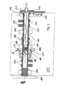
- the axial cyclone after Fig. 2 is housed within a motor housing 14.
- the basic structure of this Axialzyklons corresponds to that after the execution in Fig. 1 , Functionally identical elements are therefore assigned the same reference numerals.
- a pre-separator 8 On the inflow side, a pre-separator 8 is provided. Within this pre-separator 8, the structure of which will be explained in more detail below, radial feed openings 9 are located in the interior of the tubular separator housing 1.
- the pre-separator 8 is formed by a funnel 10 which coaxially surrounds the tubular separator housing 1 in the form of a conical jacket in the region of the feed openings 9.
- the conical shell of the funnel 10 has an axially closed and an axially open end, wherein the closed end is at its narrow and the open end at its wide opening cross-section.
- the swirl generator 6 In the cavity of the tubular separation housing 1, the swirl generator 6 is provided with a relatively small axial distance to the supply openings 9.
- This swirl generator 6 has as in the embodiment according to Fig. 1 , in whose description is not discussed here, the task to put the cavity of the tubular Abscheidegeophuses flowing oil mist stream in a swirling flow to thereby downstream of the swirl generator 6 an accumulation separated, liquid oil on the inner wall of the tubular Abscheidegephases 1 in a particularly to achieve high levels.
- the resultant by such an attachment oil film is indicated in the drawing with near-wall flow arrows.
- the at least largely freed from liquid oil fractions, gaseous portion of the oil mist stream is exposed downstream of the swirl generator 6 by bold flow arrows.
- the inner lateral surface of the conical jacket of the funnel 10 is in particular designed like a screw conveyor, specifically in a region which is outlined in the drawing by a dot-dash line 11 in each case.
- the oil mist stream is rotated by the rotating tubular separation housing 1 with which the conical jacket is fixed before this oil mist stream enters the radial supply openings 9 into the interior of the tubular separation housing 1 arrives.
- Due to the conical or funnel-shaped course of the conical jacket an axial force component in the direction of the axially open end of the conical jacket arises in the oil deposited on the inner wall of the conical jacket by centrifugal forces as an oil film.
- This axial component results from the fact that the centrifugal force increases with increasing inner diameter of the inner surface of the conical jacket, resulting in a positive centrifugal force gradient towards the open end of the conical jacket.
- This gradient results in an axial force component toward the open end of the conical shell which drives oil deposited on the inner circumference of the conical shell toward the axially open end from which it can flow.
- the conical jacket fulfills the function of a pre-separator 8.
- the main separation takes place in the cavity of the tubular separator housing 1.
- the oil mist stream entering the cavity through the radial feed openings 9 becomes set by the axially relatively close to these openings 9 in the cavity of the tubular separator housing 1 swirl generator 6 in swirl.
- liquid oil components within the oil mist stream can settle particularly effectively as an oil film on the inner wall of the cavity of the tubular separator housing 1.
- a flow of the oil mist through the conical jacket as a pre-separator 8 and the cavity within the tubular separator housing 1 is generated by a negative pressure, which is exposed to the cavity of the tubular Abscheidegephaseuses.
- the discharge channel 5 is arranged axially aligned with respect to the axis of the tubular separation housing 1. It has an axial distance relative to the tubular separator housing 1, since a receiving space 4 is provided between it and the end of the tubular separator housing 1.
- a funnel region 12 projects into the receiving region 4 from the end of the tubular separator housing 1.
- a flow-ring channel 13 exists between the outer circumference of this funnel region 12 and an approximately complementary outer wall of the receiving region 4.
- This flow-channel 13 opens in the region of the narrow end of the funnel portion 12 outwardly into that of the motor housing wall Enclosed motor housing interior 15.
- corresponding flow directing means 16 are provided on the outer circumference of the funnel region 12.
- any required drive means for the tubular separator housing 1 is not shown in the drawing.
- the rotational energy for the tubular separator housing 1 may be sufficiently applied by the oil mist stream itself and reacted in the swirl generator.
- An axially hollow camshaft 101 with a cavity 102 is rotatably mounted in a camshaft housing 103.
- the bearings of the camshaft are indicated by 104.
- the camshaft 101 is driven via a sprocket 105 located outside the camshaft housing 103.
- An oil mist stream, to be separated from the oil as the liquid phase is indicated by arrows A.
- the oil mist stream to be separated enters the cavity 102 of the camshaft 101 through oil mist supply openings 106 provided in the wall of the camshaft 101.
- a hopper surrounds coaxially with the axis of the camshaft 101 the conical shell 107 has an axially closed and an axially open end, wherein the closed end is at its narrow and the open end at its wide opening cross-section.
- a swirl generator 108 is provided at a relatively small axial distance to the oil mist supply openings 106.
- This swirl generator 108 has the task to put the cavity 102 of the camshaft 101 flowing through the oil mist stream in a swirl flow to thereby downstream of the swirl generator 108 can accumulate a separated, liquid oil on the inner wall of the camshaft 101 to achieve a particularly high degree.
- the resultant by such an attachment oil film is indicated in the drawing with dashed lines 109.
- the at least largely freed from liquid oil fractions gaseous fraction of the oil mist stream is indicated downstream of the swirl generator 108 with arrows 10.
- the inner circumferential surface of the conical shell 107 is formed Schnecken everydayartig and that in an area which is outlined in the drawing, each with a dotted line 111.
- the oil mist stream is rotated by the rotating camshaft 101, to which the conical shell 107 is fixed, before this oil mist stream enters the radial oil supply ports 106 of the camshaft 101.
- an axial force component in the direction of the axially open end of the conical shell 107 is formed in the oil separated by centrifugal forces as oil film on the inner wall of the conical shell 107.
- This axial component results from the fact that the centrifugal force increases with increasing inner diameter of the inner surface of the conical shell 107 conical shell 107, resulting in a positive centrifugal force gradient towards the open end of the conical shell.
- This gradient in turn leads to an axial component of force in the direction of the open end of the conical shell 107, which drives oil deposited on the inner circumference of the conical jacket to the axially open end, from where it can flow off radially in accordance with the arrows B.
- the conical jacket 107 fulfills the function of a pre-separator.
- a flow of the oil mist through the conical jacket as a pre-separator and the cavity 102 of the camshaft 102nd is generated by a negative pressure, the cavity 102 of the camshaft 101 is exposed.
- the gas discharge channel 113 is arranged axially aligned with respect to the axis of the camshaft 101, namely abutting the respective end face of the camshaft 101.
- the gas discharge passage 113 does not protrude like a dip tube into the cavity 102 of the camshaft 101.
- the opening cross section of the gas discharge passage 113 may be identical to that of the cavity 102 of the camshaft 101.
- the oil discharge passage 112 is formed adjacent to the respective end of the camshaft 101 as a ring passage surrounding the gas discharge passage 113, through which separated liquid oil can flow.
- the annular region of the oil discharge channel 112 merges into an approximately tubular channel section, in which separated liquid oil can flow off due to gravity. From this area, the separated, liquid oil can flow into the crank chamber of an internal combustion engine containing the camshaft 102. Since there is a pressure gradient in the direction of the cavity 102 of the camshaft 101 between the cavity 102 of the camshaft 101, on the one hand, and the crank chamber, on the other hand, a so-called gravity valve 117 can be provided in the oil discharge passage 112 be arranged.
- Gravity valve is here understood to mean a closing valve 117 which is opened by the weight of the liquid oil accumulating upstream of the valve.
- the swirl generator 108 can be easily inserted into the cavity 102 of the camshaft 101 for mounting.
- a fixing of the swirl generator 108 can be carried out by, for example, a double-sided caulking with material from the inner wall of the camshaft 102.
- only one Stemmwerkmaschine must be inserted axially into the cavity, on both sides of the camshaft 101, when the swirl generator 102 is to be caulked to both sides axially.
- the caulked areas are entered in the drawing with 114.
- the gas discharge passage 113 is fixedly connected to the camshaft housing 103.
- the interior of the camshaft housing 103 is in the region of the oil discharge passage 103 opposite to this sealed within an adjacent bearing 104 by a ring seal 116.
Landscapes
- Engineering & Computer Science (AREA)
- Mechanical Engineering (AREA)
- General Engineering & Computer Science (AREA)
- Lubrication Details And Ventilation Of Internal Combustion Engines (AREA)
- Centrifugal Separators (AREA)
Claims (12)
- Dispositif de séparateur de nuage d'huile centrifuge d'un moteur à combustion interne intégré dans un logement de séparateur tubulaire (1), dans lequel- le logement de séparateur tubulaire (1) est pourvu,- à une première extrémité d'ouvertures d'introduction de nuage d'huile radiales (9) destinées au nuage d'huile à introduire dans l'espace creux axial du logement de séparateur tubulaire et- à la deuxième extrémité à des fins d'évacuation respectivement d'un côté d'un canal d'évacuation d'huile radial (13) destiné à l'huile séparée comme phase liquide et d'un autre côté d'un canal d'évacuation de gaz axial (5) destiné au courant de nuage d'huile restant après la fraction de liquide séparée,caractérisé en ce que- un pré-séparateur de nuage d'huile centrifuge en tant que pré-séparateur (8) relié solidement au logement de séparateur tubulaire (1) est bordé par les ouvertures d'introduction de nuage d'huile radiales (9) et- à l'intérieur de l'espace creux axial du logement de séparateur tubulaire (1), un générateur de torsion (6) est prévu en tant que séparateur final.
- Dispositif de séparateur de nuage d'huile centrifuge selon la revendication 1,
caractérisé en ce que
le pré-séparateur (8) est réalisé comme une gaine conique enveloppant coaxialement le logement de séparateur tubulaire (1), entourant les ouvertures d'introduction de nuage d'huile radiales (9), dans lequel l'extrémité étroite de celui-ci est fermée axialement et est coordonnée en adjacence aux ouvertures d'introduction de nuage d'huile radiales (9). - Dispositif de séparateur de nuage d'huile centrifuge selon la revendication 2,
caractérisé en ce que
la surface intérieure de la gaine conique du pré-séparateur (8) est réalisée en forme de vis sans fin avec un dispositif convoyeur placé à l'extrémité large de la gaine conique. - Dispositif de séparateur de nuage d'huile centrifuge selon une des revendications précédentes,
caractérisé en ce que
le générateur de torsion (6) constitue un composant inséré dans l'espace creux axial du logement de séparateur tubulaire (1) et y est fixé par une déformation du matériau ondulé ayant lieu après la pose. - Dispositif de séparateur de nuage d'huile centrifuge selon une des revendications précédentes,
caractérisé en ce que
le canal d'évacuation de gaz axial (5) prévu à la deuxième extrémité du logement de séparateur tubulaire (1) est réalisé de manière à s'aligner axialement de manière stationnaire par rapport au logement de séparateur tubulaire (1), positionné rotativement, devant la face frontale afférente de celui-ci. - Dispositif de séparateur de nuage d'huile centrifuge pour un moteur à combustion interne selon une des revendications précédentes, intégré dans un logement de séparateur tubulaire (1) sous la forme d'un cyclone axial, dans lequel le logement de séparateur (1) exerce exclusivement la fonction du séparateur de nuage d'huile.
- Dispositif de séparateur de nuage d'huile centrifuge pour un moteur à combustion interne selon une des revendications précédentes, intégré dans un logement de séparateur (1) tubulaire, apte à entrer en rotation autour de l'axe du tube et entrant en rotation autour de cet axe en fonctionnement avec séparation sous la forme d'un cyclone axial, dans lequel- le logement de séparateur (1) peut être décalé en rotation avec action de séparation uniquement par l'énergie d'écoulement agissant comme force d'entraînement sur le générateur de torsion (6), à partir du courant de nuage d'huile, ou- le logement de séparateur (1) est raccordé à un entraînement électromotorisé.
- Dispositif de séparateur de nuage d'huile centrifuge selon la deuxième alternative selon la revendication 7,
caractérisé en ce que
le logement de séparateur (1) est réalisé comme un rotor de l'entraînement électromotorisé. - Dispositif de séparateur de nuage d'huile centrifuge selon une des revendications précédentes comportant une extrémité axiale située en aval, caractérisée par les caractéristiques suivantes,- le logement de séparateur (1) tubulaire positionné rotativement débouche dans un espace de réceptacle (4) s'élargissant radialement d'un logement de réceptacle stationnaire,- à partir de l'espace de réceptacle (4), un canal de décharge (5) espacé axialement par rapport à l'extrémité axiale concernée du logement de séparateur tubulaire (1) mène en alignement axial à l'axe de tuyau du logement de séparateur (1) à des fins d'évacuation de la fraction de gaz du nuage d'huile précédemment traité, alors que une ouverture d'écoulement (7) destinée à l'huile à évacuer est prévue dans une zone géodésiquement située en dessous de l'espace de réceptacle (4).
- Dispositif de séparateur de nuage d'huile centrifuge selon la revendication 9,
caractérisé en ce que
l'espace de réceptacle (4) est réalisée en forme d'entonnoir avec un diamètre s'élargissant en aval. - Dispositif de séparateur de nuage d'huile centrifuge selon la revendication 10,
caractérisé en ce que
l'extrémité située en aval du logement de séparateur tubulaire (1) aboutit à une zone d'entonnoir (12) conique, s'étendant à l'intérieur de l'espace de réceptacle (4), dans lequel ente la circonférence extérieure de la zone en forme d'entonnoir (12) et une paroi extérieure s'étendant complémentairement de l'espace de réceptacle (4) un canal annulaire d'écoulement (13) avec une épaisseur continuellement identique est réalisé avec une voie d'écoulement sur son extrémité contiguë au logement de séparateur tubulaire (1). - Dispositif de séparateur de nuage d'huile centrifuge selon la revendication 11,
caractérisé en ce que
sur le côté extérieur de la zone d'entonnoir (12), des moyens de guidage d'écoulement (16) pour générer écoulement allant vers l'extrémité ouverte à l'extérieur du canal annulaire d'écoulement (13) sont prévus.
Applications Claiming Priority (3)
| Application Number | Priority Date | Filing Date | Title |
|---|---|---|---|
| DE200510022254 DE102005022254A1 (de) | 2005-05-10 | 2005-05-10 | In eine axial hohle Nockenwelle eines Verbrennungsmotors integrierte Zentrifugal-Ölnebelabscheidereinrichtung |
| DE102005042725A DE102005042725A1 (de) | 2004-09-23 | 2005-09-08 | Axialzyklon als Ölnebelabscheider eines Kraftfahrzeug-Verbrennungsmotors |
| PCT/DE2006/000781 WO2006119737A1 (fr) | 2005-05-10 | 2006-05-06 | Dispositif centrifuge separateur de brouillard d'huile integre dans un arbre axialement creux d'un moteur a combustion interne |
Publications (3)
| Publication Number | Publication Date |
|---|---|
| EP1880085A1 EP1880085A1 (fr) | 2008-01-23 |
| EP1880085B1 true EP1880085B1 (fr) | 2010-08-11 |
| EP1880085B2 EP1880085B2 (fr) | 2013-10-09 |
Family
ID=37000109
Family Applications (1)
| Application Number | Title | Priority Date | Filing Date |
|---|---|---|---|
| EP06722839.5A Ceased EP1880085B2 (fr) | 2005-05-10 | 2006-05-06 | Dispositif centrifuge separateur de brouillard d'huile integre dans un arbre axialement creux d'un moteur a combustion interne |
Country Status (5)
| Country | Link |
|---|---|
| US (1) | US7717101B2 (fr) |
| EP (1) | EP1880085B2 (fr) |
| JP (1) | JP5124448B2 (fr) |
| DE (2) | DE502006007644D1 (fr) |
| WO (1) | WO2006119737A1 (fr) |
Cited By (1)
| Publication number | Priority date | Publication date | Assignee | Title |
|---|---|---|---|---|
| DE102011000458A1 (de) | 2011-02-02 | 2012-08-02 | Thyssenkrupp Presta Teccenter Ag | Welle, insbesondere Nockenwelle mit einem hohlen Wellenabschnitt |
Families Citing this family (70)
| Publication number | Priority date | Publication date | Assignee | Title |
|---|---|---|---|---|
| US7065954B2 (en) * | 2004-04-20 | 2006-06-27 | Gustavo Francisco Labala | Turbine, particularly useful for small aircraft |
| US7648543B2 (en) | 2004-09-21 | 2010-01-19 | Cummins Filtration Ip Inc. | Multistage variable impactor |
| US7473291B2 (en) | 2004-09-21 | 2009-01-06 | Cummins Filtration Ip, Inc. | Inertial gas-liquid separator with variable flow actuator |
| US8048212B2 (en) | 2004-09-21 | 2011-11-01 | Cummins Filtration Ip, Inc. | Inertial gas-liquid separator with valve and variable flow actuator |
| US7614390B2 (en) | 2007-08-23 | 2009-11-10 | Cummins Filtration Ip Inc. | Two stage drainage gas-liquid separator |
| US7406960B2 (en) | 2004-12-10 | 2008-08-05 | Fleetguard, Inc. | Oil mist removal device with oil fill |
| US7896946B1 (en) | 2004-09-21 | 2011-03-01 | Cummins Filtration Ip, Inc. | Multistage multicontroller variable impactor |
| US8075668B2 (en) | 2005-03-29 | 2011-12-13 | Dresser-Rand Company | Drainage system for compressor separators |
| DE102006012611A1 (de) | 2006-03-20 | 2007-09-27 | Mahle International Gmbh | Zylinderkopf eines Verbrennungsmotors |
| DE102006024817A1 (de) * | 2006-05-29 | 2007-12-06 | Mahle International Gmbh | Zylinderkopf eines Verbrennungsmotors |
| US7678169B1 (en) | 2006-07-12 | 2010-03-16 | Cummins Filtration Ip Inc. | Oil fill cap with air/oil separator |
| JP5000419B2 (ja) * | 2006-08-16 | 2012-08-15 | 富士重工業株式会社 | エンジンのブリーザ装置 |
| EP2063978B1 (fr) | 2006-09-19 | 2014-07-09 | Dresser-Rand Company | Joint rotatif pour séparateur à tambour |
| CA2663531C (fr) | 2006-09-21 | 2014-05-20 | William C. Maier | Ensemble separateur a tambour et rotor de compresseur |
| WO2008039733A2 (fr) | 2006-09-25 | 2008-04-03 | Dresser-Rand Company | Système de montage pour compresseur |
| WO2008039446A2 (fr) | 2006-09-25 | 2008-04-03 | Dresser-Rand Company | Déflecteur à fluides destiné à des dispositifs de séparation de fluides |
| BRPI0717087B1 (pt) | 2006-09-25 | 2018-10-16 | Dresser Rand Co | sistema de carretel conector para conectar um primeiro componente e um segundo componente de um sistema de compressão industrial |
| MX2009003175A (es) | 2006-09-25 | 2009-04-03 | Dresser Rand Co | Cubierta de acceso para bobina conectora presurizada. |
| CA2663883C (fr) | 2006-09-25 | 2015-02-03 | Kevin M. Majot | Systeme de protection de couplage |
| EP2415507A1 (fr) | 2006-09-26 | 2012-02-08 | Dresser-Rand Company | Dispositif de séparation de fluides statique amélioré |
| US7594501B2 (en) * | 2006-12-22 | 2009-09-29 | Dichtungstechnik G. Bruss Gmbh & Co., Kg | Cylinder head cover for an internal combustion engine |
| FR2913061B1 (fr) * | 2007-02-27 | 2009-05-22 | Snecma Sa | Systeme de deshuilage pour moteur d'aeronef. |
| JP4884279B2 (ja) * | 2007-03-30 | 2012-02-29 | 本田技研工業株式会社 | ブリーザ装置を備える内燃機関 |
| US8166958B2 (en) * | 2007-08-15 | 2012-05-01 | GM Global Technology Operations LLC | Positive crankcase ventilation system for an internal combustion engine |
| US7857883B2 (en) | 2007-10-17 | 2010-12-28 | Cummins Filtration Ip, Inc. | Inertial gas-liquid separator with constrictable and expansible nozzle valve sidewall |
| JP2009121341A (ja) * | 2007-11-14 | 2009-06-04 | Toyota Boshoku Corp | クランクルーム換気装置 |
| WO2009111616A2 (fr) | 2008-03-05 | 2009-09-11 | Dresser-Rand Company | Ensemble compresseur comprenant séparateur et pompe à éjecteur |
| DE102008017919A1 (de) * | 2008-04-08 | 2009-10-15 | Mann + Hummel Gmbh | Abscheider für eine Kurbelgehäuseentlüftung einer Brennkraftmaschine |
| US8075655B2 (en) | 2008-06-17 | 2011-12-13 | Cummins Filtration Ip, Inc. | Rotative inertial impactor gas-oil separator for internal combustion engine |
| US8079805B2 (en) | 2008-06-25 | 2011-12-20 | Dresser-Rand Company | Rotary separator and shaft coupler for compressors |
| US8062400B2 (en) | 2008-06-25 | 2011-11-22 | Dresser-Rand Company | Dual body drum for rotary separators |
| US7922218B2 (en) | 2008-06-25 | 2011-04-12 | Dresser-Rand Company | Shear ring casing coupler device |
| US7992551B2 (en) * | 2008-11-26 | 2011-08-09 | Toyota Motor Engineering & Manufacturing North America, Inc. | Oil capturing device having a rotary component |
| DE102009012400A1 (de) * | 2009-03-10 | 2010-09-23 | Thyssenkrupp Presta Teccenter Ag | Hohlkörper mit integrierter Ölabscheideeinrichtung |
| DE102009012401A1 (de) * | 2009-03-10 | 2010-09-23 | Thyssenkrupp Presta Teccenter Ag | Hohlkörper mit integrierter Ölabscheideeinrichtung |
| DE102009012402A1 (de) | 2009-03-10 | 2010-09-23 | Thyssenkrupp Presta Teccenter Ag | Wellenkörper mit integrierter Ölabscheideeinrichtung |
| US8087901B2 (en) | 2009-03-20 | 2012-01-03 | Dresser-Rand Company | Fluid channeling device for back-to-back compressors |
| US8210804B2 (en) | 2009-03-20 | 2012-07-03 | Dresser-Rand Company | Slidable cover for casing access port |
| US8061972B2 (en) | 2009-03-24 | 2011-11-22 | Dresser-Rand Company | High pressure casing access cover |
| US8414692B2 (en) | 2009-09-15 | 2013-04-09 | Dresser-Rand Company | Density-based compact separator |
| US9095856B2 (en) | 2010-02-10 | 2015-08-04 | Dresser-Rand Company | Separator fluid collector and method |
| DE102010012481A1 (de) | 2010-03-24 | 2011-09-29 | Schaeffler Technologies Gmbh & Co. Kg | Brennkraftmaschine mit einer Vorrichtung zur Veränderung der relativen Winkellage einer Nockenwelle gegenüber einer Kurbelwelle |
| SE534773C2 (sv) * | 2010-04-09 | 2011-12-13 | Alfa Laval Corp Ab | Centrifugalseparator anordnad inuti en förbränningsmotor |
| DE102010022483B4 (de) | 2010-06-02 | 2016-09-01 | Thyssenkrupp Presta Teccenter Ag | Welle, insbesondere Nockenwelle |
| DE102010033955A1 (de) * | 2010-08-10 | 2012-02-16 | Thyssenkrupp Presta Teccenter Ag | Hohlkörper mit integrierter Ölabscheideeinrichtung |
| US8657907B2 (en) | 2010-06-02 | 2014-02-25 | Thyssenkrupp Presta Teccenter Ag | Tubular camshaft with integrated oil separator |
| US8580002B2 (en) * | 2010-07-09 | 2013-11-12 | Dresser-Rand Company | Multistage separation system |
| WO2012009158A2 (fr) | 2010-07-15 | 2012-01-19 | Dresser-Rand Company | Séparateur rotatif en ligne amélioré |
| US8663483B2 (en) | 2010-07-15 | 2014-03-04 | Dresser-Rand Company | Radial vane pack for rotary separators |
| US8657935B2 (en) | 2010-07-20 | 2014-02-25 | Dresser-Rand Company | Combination of expansion and cooling to enhance separation |
| US8821362B2 (en) | 2010-07-21 | 2014-09-02 | Dresser-Rand Company | Multiple modular in-line rotary separator bundle |
| JP5936144B2 (ja) | 2010-09-09 | 2016-06-15 | ドレッサー ランド カンパニーDresser−Rand Company | 洗浄可能に制御された排水管 |
| JP5551556B2 (ja) * | 2010-09-30 | 2014-07-16 | 富士重工業株式会社 | エンジンのブリーザ装置 |
| US8994237B2 (en) | 2010-12-30 | 2015-03-31 | Dresser-Rand Company | Method for on-line detection of liquid and potential for the occurrence of resistance to ground faults in active magnetic bearing systems |
| EP2659277B8 (fr) | 2010-12-30 | 2018-05-23 | Dresser-Rand Company | Procédé de détection en ligne de défauts de résistance à la masse dans des systèmes de palier magnétique actif |
| US20120247250A1 (en) * | 2011-03-31 | 2012-10-04 | General Electric Company | Gearbox and oil spreader thereof |
| US9551349B2 (en) | 2011-04-08 | 2017-01-24 | Dresser-Rand Company | Circulating dielectric oil cooling system for canned bearings and canned electronics |
| US8876389B2 (en) | 2011-05-27 | 2014-11-04 | Dresser-Rand Company | Segmented coast-down bearing for magnetic bearing systems |
| US8851756B2 (en) | 2011-06-29 | 2014-10-07 | Dresser-Rand Company | Whirl inhibiting coast-down bearing for magnetic bearing systems |
| DE102013102858A1 (de) | 2013-03-20 | 2014-09-25 | Thyssenkrupp Presta Teccenter Ag | Ölgeschmierte Arbeitsmaschine |
| DE102013105521A1 (de) | 2013-05-29 | 2014-12-18 | Thyssenkrupp Presta Teccenter Ag | Wellenanordnung für eine ölgeschmierte Arbeitsmaschine sowie ölgeschmierte Arbeitsmaschine |
| CN103362595B (zh) * | 2013-07-04 | 2016-08-10 | 浙江吉利汽车研究院有限公司杭州分公司 | 一种具油气分离功能的凸轮轴组件 |
| US9765644B2 (en) | 2015-01-20 | 2017-09-19 | United Technologies Corporation | Deoiler debris baffle |
| FR3056635B1 (fr) * | 2016-09-26 | 2020-05-29 | Safran Helicopter Engines | Systeme de deshuilage d'un melange air/huile de pressurisation d'etancheites d'une turbomachine |
| US11097285B2 (en) | 2018-01-11 | 2021-08-24 | Kuhn Performance Technologies, Llc | Crankcase ventilation management devices, systems, and methods |
| JP7340318B2 (ja) | 2019-12-20 | 2023-09-07 | 株式会社Subaru | 遠心式オイルミストセパレータ、レシプロエンジン及び航空機 |
| US11268453B1 (en) * | 2021-03-17 | 2022-03-08 | Pratt & Whitney Canada Corp. | Lubrication system for aircraft engine reduction gearbox |
| US11719326B2 (en) * | 2021-04-19 | 2023-08-08 | The Boeing Company | Demister for a gearing system and method |
| CN114412643B (zh) * | 2022-01-25 | 2024-08-06 | 中国航发贵阳发动机设计研究所 | 集合油气分离功能的多级回油装置 |
| CN117101313B (zh) * | 2023-08-24 | 2024-05-07 | 中国航发燃气轮机有限公司 | 一种油雾分离器及其燃气轮机 |
Family Cites Families (30)
| Publication number | Priority date | Publication date | Assignee | Title |
|---|---|---|---|---|
| US1979025A (en) * | 1934-10-30 | Statfs patfnt offiff | ||
| US2818047A (en) * | 1954-11-22 | 1957-12-31 | Continental Motors Corp | Centrifugal breather |
| FR1590886A (fr) | 1968-11-06 | 1970-04-20 | ||
| JPS5392973A (en) * | 1977-01-26 | 1978-08-15 | Sanetsu Kk | Oil mist remover |
| JPS585044Y2 (ja) * | 1979-04-16 | 1983-01-28 | 日産自動車株式会社 | 内燃機関のブロ−バイガス環元装置用オイルセパレ−タ |
| JPS612259Y2 (fr) * | 1981-04-24 | 1986-01-24 | ||
| JPS58183918U (ja) * | 1982-06-01 | 1983-12-07 | いすゞ自動車株式会社 | Pcvシステムにおけるオイル分離装置 |
| JPS60128915U (ja) * | 1984-02-08 | 1985-08-29 | トヨタ自動車株式会社 | ブロ−バイガスのオイル分離装置 |
| JPS60209620A (ja) * | 1984-04-03 | 1985-10-22 | Fuji Heavy Ind Ltd | 内燃機関のブロ−バイガス還元装置 |
| JPS61175213A (ja) * | 1985-01-30 | 1986-08-06 | Honda Motor Co Ltd | エンジンにおけるカムケ−スのブリ−ザ装置 |
| DE3541204A1 (de) | 1985-11-21 | 1987-05-27 | Audi Ag | Oelabscheider fuer die kurbelgehaeuseentlueftung einer brennkraftmaschine |
| JPH0625624Y2 (ja) * | 1986-07-17 | 1994-07-06 | トヨタ自動車株式会社 | ブロ−バイガスのオイル分離装置 |
| JP2504073B2 (ja) | 1987-10-07 | 1996-06-05 | 三菱自動車工業株式会社 | オイルセパレ―タ機構付カムシャフト |
| JPH01179113U (fr) * | 1988-06-08 | 1989-12-22 | ||
| JPH08284634A (ja) * | 1995-04-07 | 1996-10-29 | Suzuki Motor Corp | ブローバイガスの気液分離装置 |
| DE19608503C2 (de) | 1996-03-05 | 1999-10-21 | Bayerische Motoren Werke Ag | Kurbelgehäuseentlüftung für eine Brennkraftmaschine |
| DE19706383C2 (de) | 1997-02-19 | 2000-05-18 | Daimler Chrysler Ag | Entlüftungsvorrichtung für ein Kurbelgehäuse einer Brennkraftmaschine |
| DE19803872C2 (de) * | 1998-01-31 | 2001-05-10 | Daimler Chrysler Ag | Entlüfungsvorrichtung für ein Kurbelgehäuse einer Brennkraftmaschine |
| DE19824041A1 (de) * | 1998-05-29 | 1999-12-02 | Stihl Maschf Andreas | Verbrennungsmotor |
| US6139595A (en) | 1998-09-18 | 2000-10-31 | Fleetguard, Inc. | Air/oil coalescer with centrifugally assisted drainage |
| DE19914166A1 (de) | 1999-03-29 | 2000-10-05 | Deutz Ag | Ölabscheider zur Reinigung von Kurbelgehäuseentlüftungsgasen einer Brennkraftmaschine |
| DE19931740C2 (de) * | 1999-07-08 | 2001-06-13 | Daimler Chrysler Ag | Hubkolbenbrennkraftmaschine mit einer Nockenwelle |
| SE518077C2 (sv) | 2000-12-01 | 2002-08-20 | Alfa Laval Corp Ab | Sätt och anordning för rening av vevhusgaser från en förbränningsmotor inrättad för framdrivande av ett transportmedel |
| DE10063903A1 (de) | 2000-12-21 | 2002-07-04 | Mann & Hummel Filter | Freistrahlzentrifuge mit integriertem Ölabscheider |
| DE10140301A1 (de) | 2001-08-16 | 2003-02-27 | Daimler Chrysler Ag | Entlüftungsvorrichtung für ein Kurbelgehäuse einer Brennkraftmaschine |
| KR100435731B1 (ko) | 2001-08-22 | 2004-06-12 | 현대자동차주식회사 | 자동차의 블로바이가스 오일분리기 |
| DE10226695A1 (de) * | 2002-06-15 | 2003-12-24 | Daimler Chrysler Ag | Zentrifugal-Ölabscheider in einem Kurbelgehäuse einer Brennkraftmaschine |
| JP4294949B2 (ja) * | 2002-12-27 | 2009-07-15 | 日産ディーゼル工業株式会社 | ロッカーカバー |
| DE10338770B4 (de) | 2003-08-23 | 2005-08-25 | Mann + Hummel Gmbh | Zentrifugalabscheider und Verfahren zur Reinigung eines Fluidstromes |
| DE102004045630A1 (de) | 2004-09-21 | 2006-04-06 | Daimlerchrysler Ag | Zentrifugalabscheider |
-
2006
- 2006-05-06 DE DE502006007644T patent/DE502006007644D1/de not_active Expired - Lifetime
- 2006-05-06 EP EP06722839.5A patent/EP1880085B2/fr not_active Ceased
- 2006-05-06 US US11/660,831 patent/US7717101B2/en not_active Expired - Fee Related
- 2006-05-06 DE DE112006000356T patent/DE112006000356A5/de not_active Withdrawn
- 2006-05-06 JP JP2008510397A patent/JP5124448B2/ja not_active Expired - Fee Related
- 2006-05-06 WO PCT/DE2006/000781 patent/WO2006119737A1/fr not_active Ceased
Cited By (3)
| Publication number | Priority date | Publication date | Assignee | Title |
|---|---|---|---|---|
| DE102011000458A1 (de) | 2011-02-02 | 2012-08-02 | Thyssenkrupp Presta Teccenter Ag | Welle, insbesondere Nockenwelle mit einem hohlen Wellenabschnitt |
| WO2012104391A1 (fr) | 2011-02-02 | 2012-08-09 | Thyssenkrupp Presta Teccenter Ag | Arbre, en particulier arbre à cames comprenant une section d'arbre creuse |
| US9803514B2 (en) | 2011-02-02 | 2017-10-31 | Thyssenkrupp Presta Teccenter Ag | Shaft, particularly a partly tubular camshaft |
Also Published As
| Publication number | Publication date |
|---|---|
| DE502006007644D1 (de) | 2010-09-23 |
| DE112006000356A5 (de) | 2007-11-22 |
| WO2006119737A1 (fr) | 2006-11-16 |
| US20070294986A1 (en) | 2007-12-27 |
| US7717101B2 (en) | 2010-05-18 |
| EP1880085B2 (fr) | 2013-10-09 |
| JP2008540906A (ja) | 2008-11-20 |
| JP5124448B2 (ja) | 2013-01-23 |
| EP1880085A1 (fr) | 2008-01-23 |
Similar Documents
| Publication | Publication Date | Title |
|---|---|---|
| EP1880085B1 (fr) | Dispositif centrifuge separateur de brouillard d'huile integre dans un arbre axialement creux d'un moteur a combustion interne | |
| EP1880090B1 (fr) | Dispositif pour purifier un gaz lors de l'evacuation de l'air contenu dans un carter de vilebrequin | |
| EP1514012B1 (fr) | Separateur d'huile centrifuge utilise dans un carter de vilebrequin d'un moteur a combustion interne | |
| EP1845238B1 (fr) | Culasse de moteur | |
| EP1422389A2 (fr) | Separateur d'huile centrifuge | |
| EP2009288A2 (fr) | Turbocompresseur doté d'un séparateur intégré | |
| DE102005042725A1 (de) | Axialzyklon als Ölnebelabscheider eines Kraftfahrzeug-Verbrennungsmotors | |
| EP2821599A1 (fr) | Moteur à réaction doté d'au moins un séparateur d'huile | |
| DE102005022254A1 (de) | In eine axial hohle Nockenwelle eines Verbrennungsmotors integrierte Zentrifugal-Ölnebelabscheidereinrichtung | |
| EP1866525B1 (fr) | Module arbre de compensation | |
| EP1645320A1 (fr) | Separateur centrifuge | |
| DE69026045T2 (de) | Flüssigkeitsentgasungspumpe | |
| EP1772193B1 (fr) | Séparateur centrifuge | |
| WO2006077021A1 (fr) | Dispositif de separation pour la separation de particules de liquides d'un milieu gazeux | |
| EP3641910A1 (fr) | Dispositif de séparation | |
| EP1998896B1 (fr) | Centrifugeuse a vis et enveloppe pleine dotee d'ouvertures d'evacuation pour le vidage partiel et le vidage residuel du tambour | |
| DE102016216826A1 (de) | Flüssigkeitsnebelabscheideeinrichtung und Kurbelgehäuseentlüftungseinrichtung | |
| DE102017114646B4 (de) | Förder- und Verdichterelement, Hohlwelle, Verbrennungsmotor und Verfahren zum Reinigen von Blowby-Gasen | |
| WO2019007858A1 (fr) | Arbre creux et procédé pour séparer un liquide | |
| DE102023206039B4 (de) | Kurbelwelle für eine Kurbelwellenanordnung einer Brennkraftmaschine sowie entsprechende Kurbelwellenanordnung | |
| DE102017210321A1 (de) | Abscheidevorrichtung | |
| DE102017210320A1 (de) | Abscheidevorrichtung | |
| EP3033499B1 (fr) | Module d'arbre à cames et dispositif d'arbre à cames | |
| DE102008012400B4 (de) | Ölnebelabscheider | |
| DE102017210325A1 (de) | Abscheidevorrichtung |
Legal Events
| Date | Code | Title | Description |
|---|---|---|---|
| PUAI | Public reference made under article 153(3) epc to a published international application that has entered the european phase |
Free format text: ORIGINAL CODE: 0009012 |
|
| 17P | Request for examination filed |
Effective date: 20061123 |
|
| AK | Designated contracting states |
Kind code of ref document: A1 Designated state(s): DE FR GB |
|
| DAX | Request for extension of the european patent (deleted) | ||
| RBV | Designated contracting states (corrected) |
Designated state(s): DE FR GB |
|
| 17Q | First examination report despatched |
Effective date: 20090525 |
|
| GRAP | Despatch of communication of intention to grant a patent |
Free format text: ORIGINAL CODE: EPIDOSNIGR1 |
|
| GRAS | Grant fee paid |
Free format text: ORIGINAL CODE: EPIDOSNIGR3 |
|
| GRAA | (expected) grant |
Free format text: ORIGINAL CODE: 0009210 |
|
| AK | Designated contracting states |
Kind code of ref document: B1 Designated state(s): DE FR GB |
|
| REG | Reference to a national code |
Ref country code: GB Ref legal event code: FG4D Free format text: NOT ENGLISH |
|
| REF | Corresponds to: |
Ref document number: 502006007644 Country of ref document: DE Date of ref document: 20100923 Kind code of ref document: P |
|
| PLBI | Opposition filed |
Free format text: ORIGINAL CODE: 0009260 |
|
| PLAX | Notice of opposition and request to file observation + time limit sent |
Free format text: ORIGINAL CODE: EPIDOSNOBS2 |
|
| 26 | Opposition filed |
Opponent name: THYSSENKRUPP PRESTA TECCENTER AG Effective date: 20110511 |
|
| REG | Reference to a national code |
Ref country code: DE Ref legal event code: R026 Ref document number: 502006007644 Country of ref document: DE Effective date: 20110511 |
|
| PLBB | Reply of patent proprietor to notice(s) of opposition received |
Free format text: ORIGINAL CODE: EPIDOSNOBS3 |
|
| PUAH | Patent maintained in amended form |
Free format text: ORIGINAL CODE: 0009272 |
|
| STAA | Information on the status of an ep patent application or granted ep patent |
Free format text: STATUS: PATENT MAINTAINED AS AMENDED |
|
| 27A | Patent maintained in amended form |
Effective date: 20131009 |
|
| AK | Designated contracting states |
Kind code of ref document: B2 Designated state(s): DE FR GB |
|
| REG | Reference to a national code |
Ref country code: DE Ref legal event code: R102 Ref document number: 502006007644 Country of ref document: DE Effective date: 20131009 |
|
| REG | Reference to a national code |
Ref country code: FR Ref legal event code: PLFP Year of fee payment: 11 |
|
| REG | Reference to a national code |
Ref country code: FR Ref legal event code: PLFP Year of fee payment: 12 |
|
| REG | Reference to a national code |
Ref country code: FR Ref legal event code: PLFP Year of fee payment: 13 |
|
| PGFP | Annual fee paid to national office [announced via postgrant information from national office to epo] |
Ref country code: FR Payment date: 20200528 Year of fee payment: 15 |
|
| PGFP | Annual fee paid to national office [announced via postgrant information from national office to epo] |
Ref country code: GB Payment date: 20200528 Year of fee payment: 15 |
|
| PGFP | Annual fee paid to national office [announced via postgrant information from national office to epo] |
Ref country code: DE Payment date: 20200728 Year of fee payment: 15 |
|
| REG | Reference to a national code |
Ref country code: DE Ref legal event code: R119 Ref document number: 502006007644 Country of ref document: DE |
|
| GBPC | Gb: european patent ceased through non-payment of renewal fee |
Effective date: 20210506 |
|
| PG25 | Lapsed in a contracting state [announced via postgrant information from national office to epo] |
Ref country code: GB Free format text: LAPSE BECAUSE OF NON-PAYMENT OF DUE FEES Effective date: 20210506 Ref country code: DE Free format text: LAPSE BECAUSE OF NON-PAYMENT OF DUE FEES Effective date: 20211201 |
|
| PG25 | Lapsed in a contracting state [announced via postgrant information from national office to epo] |
Ref country code: FR Free format text: LAPSE BECAUSE OF NON-PAYMENT OF DUE FEES Effective date: 20210531 |