EP1514340B1 - Elektrischer synchronmotor mit konzentrierter wicklung - Google Patents
Elektrischer synchronmotor mit konzentrierter wicklung Download PDFInfo
- Publication number
- EP1514340B1 EP1514340B1 EP03755951A EP03755951A EP1514340B1 EP 1514340 B1 EP1514340 B1 EP 1514340B1 EP 03755951 A EP03755951 A EP 03755951A EP 03755951 A EP03755951 A EP 03755951A EP 1514340 B1 EP1514340 B1 EP 1514340B1
- Authority
- EP
- European Patent Office
- Prior art keywords
- coils
- phase
- accordance
- cycle
- teeth
- Prior art date
- Legal status (The legal status is an assumption and is not a legal conclusion. Google has not performed a legal analysis and makes no representation as to the accuracy of the status listed.)
- Expired - Lifetime
Links
- 230000001360 synchronised effect Effects 0.000 title claims abstract description 52
- 238000004804 winding Methods 0.000 claims abstract description 74
- 238000000819 phase cycle Methods 0.000 claims abstract description 46
- 238000000034 method Methods 0.000 claims description 24
- 230000004907 flux Effects 0.000 claims description 16
- 238000006073 displacement reaction Methods 0.000 claims description 7
- 230000005294 ferromagnetic effect Effects 0.000 claims description 7
- 230000002146 bilateral effect Effects 0.000 claims description 3
- 210000004508 polar body Anatomy 0.000 claims description 3
- 230000005284 excitation Effects 0.000 description 26
- 230000005291 magnetic effect Effects 0.000 description 14
- 239000004020 conductor Substances 0.000 description 9
- 230000008901 benefit Effects 0.000 description 5
- 238000010586 diagram Methods 0.000 description 4
- 230000000750 progressive effect Effects 0.000 description 4
- 238000010276 construction Methods 0.000 description 3
- 230000002093 peripheral effect Effects 0.000 description 3
- 230000009467 reduction Effects 0.000 description 3
- 238000004088 simulation Methods 0.000 description 3
- 230000009471 action Effects 0.000 description 2
- 238000009826 distribution Methods 0.000 description 2
- 230000000694 effects Effects 0.000 description 2
- 230000014509 gene expression Effects 0.000 description 2
- 238000003475 lamination Methods 0.000 description 2
- 238000004519 manufacturing process Methods 0.000 description 2
- 239000000523 sample Substances 0.000 description 2
- 238000004904 shortening Methods 0.000 description 2
- 230000001052 transient effect Effects 0.000 description 2
- RYGMFSIKBFXOCR-UHFFFAOYSA-N Copper Chemical compound [Cu] RYGMFSIKBFXOCR-UHFFFAOYSA-N 0.000 description 1
- 239000004809 Teflon Substances 0.000 description 1
- 229920006362 Teflon® Polymers 0.000 description 1
- 239000003831 antifriction material Substances 0.000 description 1
- 230000033228 biological regulation Effects 0.000 description 1
- 238000012790 confirmation Methods 0.000 description 1
- 229910052802 copper Inorganic materials 0.000 description 1
- 239000010949 copper Substances 0.000 description 1
- 230000007547 defect Effects 0.000 description 1
- 238000011161 development Methods 0.000 description 1
- 230000018109 developmental process Effects 0.000 description 1
- 230000005674 electromagnetic induction Effects 0.000 description 1
- 238000005516 engineering process Methods 0.000 description 1
- 238000011156 evaluation Methods 0.000 description 1
- 239000003302 ferromagnetic material Substances 0.000 description 1
- 238000001914 filtration Methods 0.000 description 1
- 230000012447 hatching Effects 0.000 description 1
- 238000010438 heat treatment Methods 0.000 description 1
- 230000006872 improvement Effects 0.000 description 1
- 238000003780 insertion Methods 0.000 description 1
- 230000037431 insertion Effects 0.000 description 1
- 230000005415 magnetization Effects 0.000 description 1
- 230000003071 parasitic effect Effects 0.000 description 1
- 238000005293 physical law Methods 0.000 description 1
- 230000001105 regulatory effect Effects 0.000 description 1
- 238000012360 testing method Methods 0.000 description 1
- 229910000859 α-Fe Inorganic materials 0.000 description 1
Images


Classifications
-
- H—ELECTRICITY
- H02—GENERATION; CONVERSION OR DISTRIBUTION OF ELECTRIC POWER
- H02K—DYNAMO-ELECTRIC MACHINES
- H02K41/00—Propulsion systems in which a rigid body is moved along a path due to dynamo-electric interaction between the body and a magnetic field travelling along the path
- H02K41/02—Linear motors; Sectional motors
- H02K41/03—Synchronous motors; Motors moving step by step; Reluctance motors
- H02K41/031—Synchronous motors; Motors moving step by step; Reluctance motors of the permanent magnet type
-
- H—ELECTRICITY
- H02—GENERATION; CONVERSION OR DISTRIBUTION OF ELECTRIC POWER
- H02K—DYNAMO-ELECTRIC MACHINES
- H02K21/00—Synchronous motors having permanent magnets; Synchronous generators having permanent magnets
- H02K21/12—Synchronous motors having permanent magnets; Synchronous generators having permanent magnets with stationary armatures and rotating magnets
- H02K21/14—Synchronous motors having permanent magnets; Synchronous generators having permanent magnets with stationary armatures and rotating magnets with magnets rotating within the armatures
- H02K21/16—Synchronous motors having permanent magnets; Synchronous generators having permanent magnets with stationary armatures and rotating magnets with magnets rotating within the armatures having annular armature cores with salient poles
-
- H—ELECTRICITY
- H02—GENERATION; CONVERSION OR DISTRIBUTION OF ELECTRIC POWER
- H02K—DYNAMO-ELECTRIC MACHINES
- H02K21/00—Synchronous motors having permanent magnets; Synchronous generators having permanent magnets
- H02K21/12—Synchronous motors having permanent magnets; Synchronous generators having permanent magnets with stationary armatures and rotating magnets
- H02K21/24—Synchronous motors having permanent magnets; Synchronous generators having permanent magnets with stationary armatures and rotating magnets with magnets axially facing the armatures, e.g. hub-type cycle dynamos
Definitions
- the present invention herein refers to a synchronous electrical concentrated coil machine or otherwise called with tooth coils and to a method for determining the assignment of the phase and the winding direction of the coils of a synchronous electrical concentrated coil machine.
- the winding with Pacinotti structure is constructively awkward to produce, as it has to be "sewn" around the toroidal ferromagnetic core, thus making hundreds of insertions, that can create constructive difficulty and irregularity of laying (both in the radial direction, with the risk of overlapping, and in the peripheral direction, with an uneven peripheral positioning of the turns of different phases, above all if the dimension of the machine is high).
- the space occupied in the air-gap by the dimensions of the conductors and the relative insulating thicknesses drastically reduces the efficiency of the magnetization; in fact, while the mechanic air-gap is the space of air comprised between the surface of the permanent magnets and the most external surface of the toroidal core wound, the magnetic gap is much greater, also comprising the radial dimension occupied by the conductors.
- WO 00/76054 discloses an axial-gap synchronous machine with 2 cycles and 3 phases.
- US-A-4 774 428 discloses a three-phase synchronous electrical machine comprising a single cycle, with 8 permanent-magnet rotor poles and a stator teeth each of which is provided with a concentrated coil, alternate coils being wound in converse directions.
- the object of the present invention is to provide for a synchronous electrical concentrated coil machine that does not contrast the presence of the teeth, but instead uses them suitably, supporting the natural tendency to convey the flux exchanged with the excitation poles of the inductor structure.
- said object is achieved by means of a synchronous electrical concentrated coil machine as defined in claim 1 and by means of a procedure for designing a synchronous electrical concentrated coil machine as defined in claim 15.
- a synchronous electrical concentrated coil machine can be produced with a progressive spatial staggering between poles and teeth.
- the numbers of the armature teeth and the inductor poles are not very different from each other; this configuration implies the achievement of electromagnetic and mechanical performances of higher quality than that of traditional machines, also resulting in numerous constructive advantages (low number of teeth, ease of winding, less length of the endwinding connections).
- tooth coil machines in accordance with the present invention, presents various constructive and operational advantages, herewith described.
- the concentrated coils windings are intrinsically tidier, due to the absence of overlayering of the endwindings among the active sides in the slots.
- the endwindings of the tooth coils are very short, with a saving of copper, reduction of the ohmic losses and of the heating of the machine, and improvement of efficiency.
- stator magnetic yoke As the coils are all the same, their separate construction is possible and convenient as occurs in transformers: this is particularly useful in the double-side structures, without stator magnetic yoke, whose teeth can be wound one by one and then mounted in the statoric frame structure.
- N f the number of phases
- N d c the number of teeth
- N p p the number of poles
- N dc the number of teeth per cycle
- N pc the number of poles per cycle
- the high number of poles gives these machines special operational characteristics and that is, they rotate (or translate) at low speed, producing high torques (thrusts) and if the torque and inertia characteristics of the mechanical load are adequate, it is also possible to start up from zero speed, with synchronisation directly at the network frequency.
- These machines can function as generators: these machines are capable of producing electromotive force of significant magnitude and frequency of industrial interest at very low rotation speed.
- the present invention deals with a new type of synchronous electrical machines characterised by windings only constituted by concentrated coils of armature, wound around the teeth of the magnetic structure.
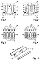
- the yoke 10 of the armature of the stator with the stator teeth 12 can be seen on which the coils 13 are wound connected to each other; the yoke 11 of the mobile inductor on which the excitation poles 14 are placed made for example by means of permanent magnets.
- the arrow placed on the excitation poles 14 indicates their polarity, in particular they are placed so that the excitation poles 14 adjacent have opposite polarity.
- FIG 2 a basic structure of a synchronous electrical concentrated coil machine of the type with double-side inductor is shown.
- the excitation poles 14 are placed made for example by means of permanent magnets.
- the statoric teeth 12 on which the coils 13 are wound connected to each other.
- ⁇ d indicates the pitch of the statoric teeth 12 and ⁇ m indicates the pitch of the magnets (or excitation poles) 14.
- rotating or linear machines can be produced, with flat or cylindrical air-gap, with single-side or double-side magnetisation, operating as motors or generators.
- the permanent magnets of the excitation poles 14 can be replaced with polar bodies fitted with windings, they also concentrated, which in such case can be denominated teeth of the mobile part (rotor or slider).
- Figure 3 shows a front view and a view from above of the controverse coils phase windings and that is one coil 13 is wound on each statoric tooth 12, wound in the direction of the arrows and that is so that the adjacent coils 13 are wound controversely. In the two views the connection between one coil and the other can also be seen.
- Figure 4 shows a front view and a view from above of the equiverse coils phase windings and that is for each couple of statoric adjacent teeth 12 only one tooth 12 is wound, resulting that the coils are wound equiversely.
- the connection between one coil and the other can also be seen.
- consecutive teeth wound receive inductor fluxes almost in phase; therefore the equiverse connection permits the maximizing of the flux linkage and thus of the electromotive force of the phase winding.
- Windings in double layer can also be produced, in which each statoric tooth 12 of armature possesses two coils, belonging to the same phase or to different phases.
- Figure 5 shows the basic structure of a synchronous electrical concentrated coil machine of the type with single-side inductor, with permanent magnet excitation poles, with windings in double layer and with controverse coils, (the type with equiverse coils can also be adopted).
- the yoke 10 of the armature of the stator can be seen with the statoric teeth 12 on each of which are wound two coils 13, the yoke 11 of the mobile inductor, and the excitation poles 14.
- Figure 6 shows the basic structure of a synchronous electrical concentrated coil machine of the type with bilateral inductor, with permanent magnet excitation poles, with windings in double layer and with controverse coils, (the type with equiverse coils can also be adopted).
- statoric teeth 12 can be seen, on each of which are wound two coils 13, the yoke 11 of the mobile inductor, the excitation poles 14, and a support 22 for the teeth 12, that does not have to be ferromagnetic.
- a first feed phase of the coils is indicated with the letters a and A, a second feed phase of the coils with the letters b and B, and a third feed phase of the coils with the letters c and C.
- the capital letter represents one winding direction of the coil for example anti-clockwise and the small letter the opposite winding direction of the coil for example clockwise.
- a rotating machine with flat air-gap can be imagined looking at Figures 5 and 6 as the side view of a structure with rotation symmetry (with rotation axis positioned vertically in the drawing plane); the coils of armature are positioned in couples around statoric cores in the shape of axially laminated parallelepipeds: in the double-side case of Figure 6, in front of them two circular rotoric yokes slide integral and aligned with each other, that support the permanent magnets, enclosing the stator like a sandwich.
- a particular characteristic of the double-side type is the absence of a ferromagnetic yoke, operating as a closing path for the tooth fluxes.
- the statoric magnetic circuit is made of aligned E cores.
- the statoric magnetic circuit is formed of aligned E cores. In such cores, the yokes only carry out the function of mechanical support, as they are not crossed by fluxes.
- the statoric magnetic circuit is cylindrical, internal, splined, with a central core in ferrite, or other ferromagnetic material with high electric resistivity, and disk teeth, laminated and piled on said core.
- the coils are bobbin-wound in the grooves of the central cylindrical armature structure.
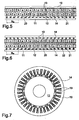
- FIG 11 The partial basic structure in prospective of a synchronous electrical concentrated coil machine of the rotating type with flat air-gap is shown in Figure 11, with two-layer controverse winding, in accordance with the present invention.
- Some statoric cores are shown in this figure, of which, as an example, only one wound with a couple of coils.
- the inductor poles (not shown), mounted on rotoric yokes, are aligned to the cores of the coils at one end (single-side structure) or to both ends (double-side structure).
- statoric cores are magnetically separated from each other (only a non-magnetic support is required, not shown in the Figure); concerning the rotor, there are two rotoric yokes integral with each other: the inductor poles axially counter-posed are aligned to each other.
- the cycle 20 is the part of the magnetic structure (or periphery) at which distance two couples (tooth - pole) present the same common position: therefore the distribution of the coils to the various phases and their winding direction is repeated from one cycle to the next.
- the number of the cycles could be any (the examples of the Figures 8, 9, 10 refer to the structure with only one cycle): nevertheless, in the case of structures of rotating machines (with cylindrical or flat air-gap), it is advisable that such number exceeds or is at least equal to 2, to avoid non-compensated magnetic attractions between stator and rotor.
- the phase-cycle 21 with reference to one layer is the portion of one cycle to which adjacent coils of the same phase extend.
- N dc (No. of armature teeth)/(cycle).
- N bc (No. of armature coils)/(cycle).
- N dc and N bc must be multiples of the no. of phases N f .
- N dcf (No. of armature teeth) / (phase-cycle).
- N bcf (No. of armature coils) / (phase-cycle).
- N dc N f N dcf .
- N bc N f N bcf .
- N dcf N dcf /2
- N bcf can be any whole number.
- N pc (No. of excitation poles) / (cycle).
- ⁇ module of the difference between N pc and N dc .
- N pc N dc ⁇ v.
- N p N pc ⁇ N c of a rotating machine
- the no. of cycles N c is also equal to the maximum no. of paths of each phase in parallel.
- the parent coil of the adjacent phase-cycle is attributed to the phase whose name Z is that of the phasor which, in the phase sequence considered (AcBaCb for three-phase machines; ABab for two-phase machines), stands ⁇ cf electrical angles from Y (in one direction or in the other); similar attribution is made for all the successive phase-cycles (always with the same path direction as the phasor diagram, for example clockwise).
- the first phase-cycle will be with the names BbBbBb and the second phase-cycle the names aAaAaA.
- the second layer presents the same phase denominations as the layer already attributed, but with a peripheral displacement of N sp teeth (the winding direction of each coil of each cycle-phase of the second layer coincides with that of the phase-cycle of the same phase of the other layer in the case of N sp even, while it is inverted if N sp is uneven):
- the displacement of layer carries out the same electromagnetic function which, in the distributed windings of the traditional machines, it is consequent to the shortening of the pitch of the windings, that is the attenuation of the winding factors of the electromotive forces of the harmonic fields of lower order.
- ⁇ 1
- the choice of N sp that optimises the waveform of the electromotive force at the terminals is the closest to N dcf /2.
- a cylindrical air-gap prototype has been constructed, of small size, obtained from a commercial asynchronous motor, in which the stator has been rewound, while the rotor has been totally redone, making it with permanent magnets.
- stator winding this is of the controverse type in two layers (each tooth wound by two coils), according to the diagram of Figure 7 (in linearized form, the configuration of Figure 5).
- N 176,47 g/min
- Ground propulsion motors particularly suitable is the flat air-gap rotating type because it can be easily integrated in the wheels (motor-wheels) and is capable of achieving high torque/mass and torque/inertia ratios.
- Tubular motors for linear drives this configuration, in which it is possible to couple the parts in relative motion by the means of the use of contact cylinders in antifriction material (for example teflon), presents a cylindrical symmetry that very satisfactorily annuls each side thrust.
- this configuration quite compact, can be used very well as actuator in many robotics, mechatronics and bio-mechanics applications.
Landscapes
- Engineering & Computer Science (AREA)
- Power Engineering (AREA)
- Chemical & Material Sciences (AREA)
- Combustion & Propulsion (AREA)
- Electromagnetism (AREA)
- Physics & Mathematics (AREA)
- Windings For Motors And Generators (AREA)
- Manufacture Of Motors, Generators (AREA)
- Superconductive Dynamoelectric Machines (AREA)
- Synchronous Machinery (AREA)
- Control Of Motors That Do Not Use Commutators (AREA)
- Control Of Ac Motors In General (AREA)
- Magnetic Treatment Devices (AREA)
- Permanent Magnet Type Synchronous Machine (AREA)
Claims (32)
- Elektrischer Synchronmotor mit konzentrierter Wicklung, der folgendes aufweist:eine Vielzahl von am Stator positionierten Zähnen (12);eine Vielzahl von um die Zähne gewickelten konzentrierten Wicklungen (13), die zum Bilden wenigstens eines Zyklus geeignet sind;eine Vielzahl von Induktorpolen (14);wobei
der Absolutwert v der Differenz zwischen der Anzahl der Vielzahl von Polen pro Zyklus Npc und der Anzahl der Vielzahl von Zähnen pro Zyklus Ndc kleiner als das zweifache der Anzahl der Phasen Nf ist;
der elektrische Winkel αcf zwischen den ersten Wicklungen von aufeinander folgenden Phasenzyklen αcf = (Ndcf + v/Nf)·180° ist, wobei ein Phasenzyklus durch eine Anzahl Nbc von benachbarten Wicklungen innerhalb eines Zyklus ausgebildet ist, die miteinander elektrisch in Reihe geschaltet sind, und Ndcf die Anzahl von Zähnen pro Phasenzyklus ist; und
die zu den ersten Wicklungen von aufeinander folgenden Phasenzyklen gehörende Phase und die Wickelrichtung der ersten Wicklungen von aufeinander folgenden Phasenzyklen durch Wechselstromzeiger bestimmt werden, die voneinander um einen Winkel getrennt sind, der gleich dem elektrischen Winkel αcf der Wechselstromzeigersequenz der Anzahl von Phasen des Motors ist, dadurch gekennzeichnet, dass die Vielzahl von konzentrierten Wicklungen, die um die Zähne gewickelt sind, zwei Wicklungen für jeden Zahn enthält und ein Schichtversatz Nsp, der Ndcf/2 am nächsten ist, gewählt ist. - Elektrischer Synchronmotor nach Anspruch 1, dadurch gekennzeichnet, dass die Phase der ersten Wicklungen den Wicklungen jedes Zyklus zugeordnet ist.
- Elektrischer Synchronmotor nach Anspruch 1, dadurch gekennzeichnet, dass er einen Generator darstellt.
- Elektrischer Synchronmotor nach Anspruch 1, dadurch gekennzeichnet, dass er einen Motor darstellt.
- Elektrischer Synchronmotor nach Anspruch 1, dadurch gekennzeichnet, dass die Vielzahl von Polen aus Permanentmagneten gebildet ist.
- Elektrischer Synchronmotor nach Anspruch 1, dadurch gekennzeichnet, dass die Vielzahl von Polen aus gewickelten Polkörpern gebildet ist, die mit geeignet geformten Polschuhen versehen sind.
- Elektrischer Synchronmotor nach Anspruch 1, dadurch gekennzeichnet, dass die Vielzahl von konzentrierten Wicklungen zueinander gerichtet sind.
- Elektrischer Synchronmotor nach Anspruch 1, dadurch gekennzeichnet, dass die Vielzahl von konzentrierten Wicklungen gegeneinander gerichtet sind.
- Elektrischer Synchronmotor nach Anspruch 1, dadurch gekennzeichnet, dass sich der elektrische Motor mit einem zylindrischen Luftspalt dreht.
- Elektrischer Synchronmotor nach Anspruch 1, dadurch gekennzeichnet, dass sich der elektrische Motor mit einem flachen Luftspalt mit Einzelseitenstruktur dreht.
- Elektrischer Synchronmotor nach Anspruch 1, dadurch gekennzeichnet, dass sich der elektrische Motor mit einem flachen Luftspalt mit Doppelseitenstruktur und Statorzähnen ohne ferromagnetisches Joch zum Schließen der Flüsse dreht.
- Elektrischer Synchronmotor nach Anspruch 1, dadurch gekennzeichnet, dass der elektrische Motor linear mit einem zylindrischen Luftspalt ist.
- Elektrischer Synchronmotor nach Anspruch 1, dadurch gekennzeichnet, dass der elektrische Motor linear mit einem zylindrischen Luftspalt mit Einzelseitenstruktur ist.
- Elektrischer Synchronmotor nach Anspruch 1, dadurch gekennzeichnet, dass der elektrische Motor linear mit einem zylindrischen Luftspalt mit zweiseitiger Struktur und Statorzähnen, die kein ferromagnetisches Joch zum Schließen der Flüsse benötigen, ist.
- Verfahren zum Entwickeln eines elektrischen Synchronmotor mit konzentrierter Wicklung, der folgendes aufweist:eine Vielzahl von am Stator positionierten Zähnen (12);eine Vielzahl von um die Zähne gewickelten konzentrierten Wicklungen (13), die zum Bilden wenigstens eines Zyklus geeignet sind;eine Vielzahl von Induktorpolen (14);dadurch gekennzeichnet, dass
der Absolutwert v der Differenz zwischen der Anzahl der Vielzahl von Polen pro Zyklus Npc und der Anzahl der Vielzahl von Zähnen pro Zyklus Ndc kleiner als das zweifache der Anzahl der Phasen Nf ist;
der elektrische Winkel αcf zwischen den ersten Wicklungen von aufeinander folgenden Phasenzyklen αcf = (Ndcf + v/Nf)·180° ist, wobei ein Phasenzyklus durch eine Anzahl Nbc von benachbarten Wicklungen innerhalb eines Zyklus ausgebildet ist, die miteinander elektrisch in Reihe geschaltet sind, und Ndcf die Anzahl von Zähnen pro Phasenzyklus ist; und
die zu den ersten Wicklungen von aufeinander folgenden Phasenzyklen gehörende Phase und die Wickelrichtung der ersten Wicklungen von aufeinander folgenden Phasenzyklen durch Wechselstromzeiger bestimmt werden, die voneinander um einen Winkel getrennt sind, der gleich dem elektrischen Winkel αcf der Wechselstromzeigersequenz der Anzahl von Phasen des Motors ist. - Verfahren nach Anspruch 15, dadurch gekennzeichnet, dass die Phase der ersten Wicklungen den Wicklungen jedes Zyklus zugeordnet ist.
- Verfahren nach Anspruch 15, dadurch gekennzeichnet, dass er einen Generator darstellt.
- Verfahren nach Anspruch 15, dadurch gekennzeichnet, dass er einen Motor darstellt.
- Verfahren nach Anspruch 15, dadurch gekennzeichnet, dass die Vielzahl von Polen aus Permanentmagneten gebildet ist.
- Verfahren nach Anspruch 15, dadurch gekennzeichnet, dass die Vielzahl von Polen aus gewickelten Polkörpern gebildet ist, die mit geeignet geformten Polschuhen versehen sind.
- Verfahren nach Anspruch 15, dadurch gekennzeichnet, dass die Vielzahl von konzentrierten Wicklungen zueinander gerichtet sind.
- Verfahren nach Anspruch 15, dadurch gekennzeichnet, dass die Vielzahl von konzentrierten Wicklungen gegeneinander gerichtet sind.
- Verfahren nach Anspruch 15, dadurch gekennzeichnet, dass die Vielzahl von konzentrierten Wicklungen, die um die Zähne gewickelt werden, zwei Wicklungen für jeden Zahn enthält und ein Schichtversatz Nsp, der Ndcf/2 am nächsten ist, gewählt wird.
- Verfahren nach Anspruch 15, dadurch gekennzeichnet, dass sich der elektrische Motor mit einem zylindrischen Luftspalt dreht.
- Verfahren nach Anspruch 15, dadurch gekennzeichnet, dass sich der elektrische Motor mit einem flachen Luftspalt mit Einzelseitenstruktur dreht.
- Verfahren nach Anspruch 15, dadurch gekennzeichnet, dass sich der elektrische Motor mit einem flachen Luftspalt mit Doppelseitenstruktur und Statorzähnen ohne ferromagnetisches Joch zum Schließen der Flüsse dreht.
- Verfahren nach Anspruch 15, dadurch gekennzeichnet, dass der elektrische Motor linear mit einem zylindrischen Luftspalt ist.
- Verfahren nach Anspruch 15, dadurch gekennzeichnet, dass der elektrische Motor linear mit einem zylindrischen Luftspalt mit Einzelseitenstruktur ist.
- Verfahren nach Anspruch 15, dadurch gekennzeichnet, dass der elektrische Motor linear mit einem zylindrischen Luftspalt mit zweiseitiger Struktur und Statorzähnen, die kein ferromagnetisches Joch zum Schließen der Flüsse benötigen, ist.
- Verfahren zum Bestimmen der Zuordnung der Phase und der Wickelrichtung der Wicklungen eines elektrischen Synchronmotor mit konzentrierter Wicklung, das die folgenden Schritte aufweist:Bestimmen des elektrischen Winkels αcf zwischen den ersten Wicklungen von aufeinander folgenden Phasenzyklen αcf = (Ndcf + v/Nf)·180°, wobei Ndcf die Anzahl von Zähnen pro Phasenzyklus ist und Nf die Anzahl von Phasen ist;Bestimmen von Wechselstromzeigern, die voneinander um einen Winkel getrennt sind, der gleich dem elektrischen Winkel αcf ist, auf der Basis der Phasensequenz der Anzahl von Phasen des Motors;Zuordnen der Namen der zuvor bestimmten Wechselstromzeiger zu den ersten Wicklungen aufeinander folgender Phasenzyklen; undZuordnen der Phase der ersten Wicklungen von Phasenzyklen zu den Wicklungen jedes Phasenzyklus.
- Verfahren zum Bestimmen der Zuordnung der Phase und der Wickelrichtung der Wicklungen eines elektrischen Synchronmotor mit konzentrierter Wicklung nach Anspruch 30, dadurch gekennzeichnet, dass der Schritt zum Zuordnen der Wicklungen jedes Phasenzyklus zu der Phase der ersten Wicklungen von Phasenzyklen den Schritt zum Zuordnen einer Wickelrichtung zu den benachbarten gegeneinander gerichteten Wicklungen aufweist.
- Verfahren zum Bestimmen der Zuordnung der Phase und der Wickelrichtung der Wicklungen eines elektrischen Synchronmotor mit konzentrierter Wicklung nach Anspruch 30, dadurch gekennzeichnet, dass der Schritt zum Zuordnen der Wicklungen jedes Phasenzyklus zu der Phase der ersten Wicklungen von Phasenzyklen den Schritt zum Zuordnen einer zueinander gerichteten Wickelrichtung zu den benachbarten Wicklungen aufweist.
Applications Claiming Priority (3)
| Application Number | Priority Date | Filing Date | Title |
|---|---|---|---|
| ITMI20021186 | 2002-05-31 | ||
| IT2002MI001186A ITMI20021186A1 (it) | 2002-05-31 | 2002-05-31 | Macchina elettrica sincrona a bobine concentrate |
| PCT/EP2003/005599 WO2003103114A1 (en) | 2002-05-31 | 2003-05-26 | Synchronous electrical concentrated coil machine |
Publications (2)
| Publication Number | Publication Date |
|---|---|
| EP1514340A1 EP1514340A1 (de) | 2005-03-16 |
| EP1514340B1 true EP1514340B1 (de) | 2006-08-09 |
Family
ID=11450017
Family Applications (1)
| Application Number | Title | Priority Date | Filing Date |
|---|---|---|---|
| EP03755951A Expired - Lifetime EP1514340B1 (de) | 2002-05-31 | 2003-05-26 | Elektrischer synchronmotor mit konzentrierter wicklung |
Country Status (7)
| Country | Link |
|---|---|
| EP (1) | EP1514340B1 (de) |
| AT (1) | ATE336096T1 (de) |
| AU (1) | AU2003242586A1 (de) |
| DE (1) | DE60307466T2 (de) |
| ES (1) | ES2270089T3 (de) |
| IT (1) | ITMI20021186A1 (de) |
| WO (1) | WO2003103114A1 (de) |
Families Citing this family (7)
| Publication number | Priority date | Publication date | Assignee | Title |
|---|---|---|---|---|
| US7723888B2 (en) | 2004-05-25 | 2010-05-25 | Marko Petek | Synchronous electromechanical transformer |
| DE102005045348A1 (de) * | 2005-09-22 | 2007-04-05 | Siemens Ag | Zahnmodul für ein permanentmagneterregtes Primärteil einer elektrischen Maschine |
| US8373319B1 (en) | 2009-09-25 | 2013-02-12 | Jerry Barnes | Method and apparatus for a pancake-type motor/generator |
| FR2957730B1 (fr) | 2010-03-17 | 2013-02-22 | Converteam Technology Ltd | Machine electrique tournante avec stator a bobinages concentriques |
| NO20101435A1 (no) * | 2010-10-15 | 2012-02-20 | Smartmotor As | Elektrisk maskin med jernløs stator og to kontraroterende rotorer |
| PL2453557T3 (pl) * | 2010-11-11 | 2023-04-11 | Grundfos Management A/S | Mokry silnik elektryczny i agregat pompowy |
| DE102013012773A1 (de) | 2012-08-03 | 2014-02-06 | Peter Graf Von Ingelheim | Elektromotor mit ungleicher Polzahl an Stator und Rotor und deren Ansteuerung |
Family Cites Families (6)
| Publication number | Priority date | Publication date | Assignee | Title |
|---|---|---|---|---|
| US4774428A (en) * | 1987-05-15 | 1988-09-27 | Synektron Corporation | Compact three-phase permanent magnet rotary machine having low vibration and high performance |
| DE3729298A1 (de) * | 1987-09-02 | 1989-03-23 | Pran Magnettechnik Europ Gmbh | Vorrichtung zur energieumwandlung |
| ES2134596T3 (es) * | 1995-03-03 | 1999-10-01 | Rolf Strothmann | Maquina electrica. |
| RU2143777C1 (ru) * | 1998-10-06 | 1999-12-27 | Закрытое Акционерное Общество Проектно-Производственно-Технологическая Фирма "ЭЛМА-Ко" | Бесконтактная электрическая машина магнитоэлектрического типа |
| US6133663A (en) * | 1999-04-01 | 2000-10-17 | A. O. Smith Corporation | Brushless permanent magnet machine |
| NO311200B1 (no) * | 1999-05-25 | 2001-10-22 | Smart Motor As | Elektrisk maskin |
-
2002
- 2002-05-31 IT IT2002MI001186A patent/ITMI20021186A1/it unknown
-
2003
- 2003-05-26 AU AU2003242586A patent/AU2003242586A1/en not_active Abandoned
- 2003-05-26 WO PCT/EP2003/005599 patent/WO2003103114A1/en not_active Ceased
- 2003-05-26 EP EP03755951A patent/EP1514340B1/de not_active Expired - Lifetime
- 2003-05-26 DE DE60307466T patent/DE60307466T2/de not_active Expired - Lifetime
- 2003-05-26 AT AT03755951T patent/ATE336096T1/de not_active IP Right Cessation
- 2003-05-26 ES ES03755951T patent/ES2270089T3/es not_active Expired - Lifetime
Also Published As
| Publication number | Publication date |
|---|---|
| ES2270089T3 (es) | 2007-04-01 |
| DE60307466D1 (de) | 2006-09-21 |
| AU2003242586A1 (en) | 2003-12-19 |
| WO2003103114A1 (en) | 2003-12-11 |
| ITMI20021186A0 (it) | 2002-05-31 |
| DE60307466T2 (de) | 2007-10-04 |
| EP1514340A1 (de) | 2005-03-16 |
| ITMI20021186A1 (it) | 2003-12-01 |
| ATE336096T1 (de) | 2006-09-15 |
Similar Documents
| Publication | Publication Date | Title |
|---|---|---|
| US11502570B2 (en) | Multi-tunnel electric machine | |
| JP4148647B2 (ja) | 軸方向磁束を有する多極電動発電機 | |
| US20240380256A1 (en) | Segmented stator for a permanent magnet electric machine having a fractional-slot concentrated winding | |
| EP2074691B1 (de) | Verbesserungen in und im bezug auf elektromotorische maschinen | |
| JP4158024B2 (ja) | 誘導電動機 | |
| WO2011030874A1 (ja) | 超電導回転電機及び超電導回転電機用固定子 | |
| JP2000350428A (ja) | 交流機器 | |
| CN107873118A (zh) | 高转子磁极开关磁阻电机的镜像 | |
| US12160149B2 (en) | Axial flux electrical machine | |
| US7521835B2 (en) | Permanent magnet machine with windings having strand transposition | |
| US20100117461A1 (en) | Electromotive machines | |
| JP2002354780A (ja) | 円筒界磁形リニアモータ | |
| EP1514340B1 (de) | Elektrischer synchronmotor mit konzentrierter wicklung | |
| JP2015512241A (ja) | 電気機械 | |
| JP2015027208A (ja) | 電磁誘導装置 | |
| Vatani et al. | Performance analysis of a novel linear switched reluctance motor with transverse-flux and four-sided structure | |
| KR20210120081A (ko) | 축 방향 자속 전기 기계 | |
| US20220069681A1 (en) | Method for winding a heavy gauge toroidal coil of an electric machine | |
| JP2000324768A (ja) | ボビン式電磁石を用いた回転電機及び電磁機器 | |
| CN222802622U (zh) | 交流闭合感应电机 | |
| US20260039157A1 (en) | Axial flux electric machine pole piece with conductive ribbons | |
| US20240339879A1 (en) | Coil assembly, armature and rotating electric machine | |
| Nastas et al. | A Study of a Fractional Slot Concentrated Wound Permanent Magnet Synchronous Motor with Grain Oriented Electric Steel Lamination for Modular Stator Geometry | |
| JPH1118329A (ja) | 永久磁石形モータ | |
| Hasan et al. | Transverse flux machines with rotary transformer concept for wide speed operations without using permanent magnet material |
Legal Events
| Date | Code | Title | Description |
|---|---|---|---|
| PUAI | Public reference made under article 153(3) epc to a published international application that has entered the european phase |
Free format text: ORIGINAL CODE: 0009012 |
|
| 17P | Request for examination filed |
Effective date: 20041223 |
|
| AK | Designated contracting states |
Kind code of ref document: A1 Designated state(s): AT BE BG CH CY CZ DE DK EE ES FI FR GB GR HU IE IT LI LU MC NL PT RO SE SI SK TR |
|
| AX | Request for extension of the european patent |
Extension state: AL LT LV MK |
|
| DAX | Request for extension of the european patent (deleted) | ||
| GRAP | Despatch of communication of intention to grant a patent |
Free format text: ORIGINAL CODE: EPIDOSNIGR1 |
|
| GRAS | Grant fee paid |
Free format text: ORIGINAL CODE: EPIDOSNIGR3 |
|
| GRAA | (expected) grant |
Free format text: ORIGINAL CODE: 0009210 |
|
| AK | Designated contracting states |
Kind code of ref document: B1 Designated state(s): AT BE BG CH CY CZ DE DK EE ES FI FR GB GR HU IE IT LI LU MC NL PT RO SE SI SK TR |
|
| PG25 | Lapsed in a contracting state [announced via postgrant information from national office to epo] |
Ref country code: IT Free format text: LAPSE BECAUSE OF FAILURE TO SUBMIT A TRANSLATION OF THE DESCRIPTION OR TO PAY THE FEE WITHIN THE PRESCRIBED TIME-LIMIT;WARNING: LAPSES OF ITALIAN PATENTS WITH EFFECTIVE DATE BEFORE 2007 MAY HAVE OCCURRED AT ANY TIME BEFORE 2007. THE CORRECT EFFECTIVE DATE MAY BE DIFFERENT FROM THE ONE RECORDED. Effective date: 20060809 Ref country code: RO Free format text: LAPSE BECAUSE OF FAILURE TO SUBMIT A TRANSLATION OF THE DESCRIPTION OR TO PAY THE FEE WITHIN THE PRESCRIBED TIME-LIMIT Effective date: 20060809 Ref country code: LI Free format text: LAPSE BECAUSE OF FAILURE TO SUBMIT A TRANSLATION OF THE DESCRIPTION OR TO PAY THE FEE WITHIN THE PRESCRIBED TIME-LIMIT Effective date: 20060809 Ref country code: CH Free format text: LAPSE BECAUSE OF FAILURE TO SUBMIT A TRANSLATION OF THE DESCRIPTION OR TO PAY THE FEE WITHIN THE PRESCRIBED TIME-LIMIT Effective date: 20060809 Ref country code: CZ Free format text: LAPSE BECAUSE OF FAILURE TO SUBMIT A TRANSLATION OF THE DESCRIPTION OR TO PAY THE FEE WITHIN THE PRESCRIBED TIME-LIMIT Effective date: 20060809 Ref country code: AT Free format text: LAPSE BECAUSE OF FAILURE TO SUBMIT A TRANSLATION OF THE DESCRIPTION OR TO PAY THE FEE WITHIN THE PRESCRIBED TIME-LIMIT Effective date: 20060809 Ref country code: SK Free format text: LAPSE BECAUSE OF FAILURE TO SUBMIT A TRANSLATION OF THE DESCRIPTION OR TO PAY THE FEE WITHIN THE PRESCRIBED TIME-LIMIT Effective date: 20060809 Ref country code: SI Free format text: LAPSE BECAUSE OF FAILURE TO SUBMIT A TRANSLATION OF THE DESCRIPTION OR TO PAY THE FEE WITHIN THE PRESCRIBED TIME-LIMIT Effective date: 20060809 |
|
| REG | Reference to a national code |
Ref country code: GB Ref legal event code: FG4D |
|
| REG | Reference to a national code |
Ref country code: CH Ref legal event code: EP |
|
| REG | Reference to a national code |
Ref country code: IE Ref legal event code: FG4D |
|
| REF | Corresponds to: |
Ref document number: 60307466 Country of ref document: DE Date of ref document: 20060921 Kind code of ref document: P |
|
| PG25 | Lapsed in a contracting state [announced via postgrant information from national office to epo] |
Ref country code: SE Free format text: LAPSE BECAUSE OF FAILURE TO SUBMIT A TRANSLATION OF THE DESCRIPTION OR TO PAY THE FEE WITHIN THE PRESCRIBED TIME-LIMIT Effective date: 20061109 Ref country code: BG Free format text: LAPSE BECAUSE OF FAILURE TO SUBMIT A TRANSLATION OF THE DESCRIPTION OR TO PAY THE FEE WITHIN THE PRESCRIBED TIME-LIMIT Effective date: 20061109 Ref country code: DK Free format text: LAPSE BECAUSE OF FAILURE TO SUBMIT A TRANSLATION OF THE DESCRIPTION OR TO PAY THE FEE WITHIN THE PRESCRIBED TIME-LIMIT Effective date: 20061109 |
|
| PG25 | Lapsed in a contracting state [announced via postgrant information from national office to epo] |
Ref country code: PT Free format text: LAPSE BECAUSE OF FAILURE TO SUBMIT A TRANSLATION OF THE DESCRIPTION OR TO PAY THE FEE WITHIN THE PRESCRIBED TIME-LIMIT Effective date: 20070109 |
|
| REG | Reference to a national code |
Ref country code: CH Ref legal event code: PL |
|
| ET | Fr: translation filed | ||
| REG | Reference to a national code |
Ref country code: ES Ref legal event code: FG2A Ref document number: 2270089 Country of ref document: ES Kind code of ref document: T3 |
|
| PLBE | No opposition filed within time limit |
Free format text: ORIGINAL CODE: 0009261 |
|
| STAA | Information on the status of an ep patent application or granted ep patent |
Free format text: STATUS: NO OPPOSITION FILED WITHIN TIME LIMIT |
|
| 26N | No opposition filed |
Effective date: 20070510 |
|
| PG25 | Lapsed in a contracting state [announced via postgrant information from national office to epo] |
Ref country code: MC Free format text: LAPSE BECAUSE OF NON-PAYMENT OF DUE FEES Effective date: 20070531 |
|
| PG25 | Lapsed in a contracting state [announced via postgrant information from national office to epo] |
Ref country code: GR Free format text: LAPSE BECAUSE OF FAILURE TO SUBMIT A TRANSLATION OF THE DESCRIPTION OR TO PAY THE FEE WITHIN THE PRESCRIBED TIME-LIMIT Effective date: 20061110 |
|
| PG25 | Lapsed in a contracting state [announced via postgrant information from national office to epo] |
Ref country code: IE Free format text: LAPSE BECAUSE OF NON-PAYMENT OF DUE FEES Effective date: 20070528 |
|
| PG25 | Lapsed in a contracting state [announced via postgrant information from national office to epo] |
Ref country code: EE Free format text: LAPSE BECAUSE OF FAILURE TO SUBMIT A TRANSLATION OF THE DESCRIPTION OR TO PAY THE FEE WITHIN THE PRESCRIBED TIME-LIMIT Effective date: 20060809 |
|
| PG25 | Lapsed in a contracting state [announced via postgrant information from national office to epo] |
Ref country code: LU Free format text: LAPSE BECAUSE OF NON-PAYMENT OF DUE FEES Effective date: 20070526 Ref country code: CY Free format text: LAPSE BECAUSE OF FAILURE TO SUBMIT A TRANSLATION OF THE DESCRIPTION OR TO PAY THE FEE WITHIN THE PRESCRIBED TIME-LIMIT Effective date: 20060809 |
|
| PG25 | Lapsed in a contracting state [announced via postgrant information from national office to epo] |
Ref country code: HU Free format text: LAPSE BECAUSE OF FAILURE TO SUBMIT A TRANSLATION OF THE DESCRIPTION OR TO PAY THE FEE WITHIN THE PRESCRIBED TIME-LIMIT Effective date: 20070210 Ref country code: TR Free format text: LAPSE BECAUSE OF FAILURE TO SUBMIT A TRANSLATION OF THE DESCRIPTION OR TO PAY THE FEE WITHIN THE PRESCRIBED TIME-LIMIT Effective date: 20060809 |
|
| REG | Reference to a national code |
Ref country code: FR Ref legal event code: PLFP Year of fee payment: 14 |
|
| REG | Reference to a national code |
Ref country code: FR Ref legal event code: PLFP Year of fee payment: 15 |
|
| REG | Reference to a national code |
Ref country code: FR Ref legal event code: PLFP Year of fee payment: 16 |
|
| PGFP | Annual fee paid to national office [announced via postgrant information from national office to epo] |
Ref country code: FI Payment date: 20180525 Year of fee payment: 16 |
|
| PGFP | Annual fee paid to national office [announced via postgrant information from national office to epo] |
Ref country code: IT Payment date: 20180523 Year of fee payment: 16 Ref country code: NL Payment date: 20180531 Year of fee payment: 16 Ref country code: FR Payment date: 20180530 Year of fee payment: 16 Ref country code: BE Payment date: 20180530 Year of fee payment: 16 |
|
| PGFP | Annual fee paid to national office [announced via postgrant information from national office to epo] |
Ref country code: GB Payment date: 20180621 Year of fee payment: 16 |
|
| PGFP | Annual fee paid to national office [announced via postgrant information from national office to epo] |
Ref country code: DE Payment date: 20181127 Year of fee payment: 16 |
|
| PGFP | Annual fee paid to national office [announced via postgrant information from national office to epo] |
Ref country code: ES Payment date: 20181119 Year of fee payment: 16 |
|
| REG | Reference to a national code |
Ref country code: DE Ref legal event code: R119 Ref document number: 60307466 Country of ref document: DE |
|
| REG | Reference to a national code |
Ref country code: NL Ref legal event code: MM Effective date: 20190601 |
|
| GBPC | Gb: european patent ceased through non-payment of renewal fee |
Effective date: 20190526 |
|
| PG25 | Lapsed in a contracting state [announced via postgrant information from national office to epo] |
Ref country code: FI Free format text: LAPSE BECAUSE OF NON-PAYMENT OF DUE FEES Effective date: 20190526 |
|
| REG | Reference to a national code |
Ref country code: BE Ref legal event code: MM Effective date: 20190531 Ref country code: BE Ref legal event code: NE Effective date: 20150407 Ref country code: BE Ref legal event code: NF Effective date: 20151112 |
|
| PG25 | Lapsed in a contracting state [announced via postgrant information from national office to epo] |
Ref country code: IT Free format text: LAPSE BECAUSE OF NON-PAYMENT OF DUE FEES Effective date: 20190526 Ref country code: DE Free format text: LAPSE BECAUSE OF NON-PAYMENT OF DUE FEES Effective date: 20191203 Ref country code: NL Free format text: LAPSE BECAUSE OF NON-PAYMENT OF DUE FEES Effective date: 20190601 Ref country code: GB Free format text: LAPSE BECAUSE OF NON-PAYMENT OF DUE FEES Effective date: 20190526 |
|
| PG25 | Lapsed in a contracting state [announced via postgrant information from national office to epo] |
Ref country code: BE Free format text: LAPSE BECAUSE OF NON-PAYMENT OF DUE FEES Effective date: 20190531 |
|
| PG25 | Lapsed in a contracting state [announced via postgrant information from national office to epo] |
Ref country code: FR Free format text: LAPSE BECAUSE OF NON-PAYMENT OF DUE FEES Effective date: 20190531 |
|
| REG | Reference to a national code |
Ref country code: ES Ref legal event code: FD2A Effective date: 20200930 |
|
| PG25 | Lapsed in a contracting state [announced via postgrant information from national office to epo] |
Ref country code: ES Free format text: LAPSE BECAUSE OF NON-PAYMENT OF DUE FEES Effective date: 20190527 |