EP1514677B1 - Rouleau assiste par depression et procédé associé - Google Patents
Rouleau assiste par depression et procédé associé Download PDFInfo
- Publication number
- EP1514677B1 EP1514677B1 EP04027390A EP04027390A EP1514677B1 EP 1514677 B1 EP1514677 B1 EP 1514677B1 EP 04027390 A EP04027390 A EP 04027390A EP 04027390 A EP04027390 A EP 04027390A EP 1514677 B1 EP1514677 B1 EP 1514677B1
- Authority
- EP
- European Patent Office
- Prior art keywords
- vacuum
- apertures
- roll
- blades
- disks
- Prior art date
- Legal status (The legal status is an assumption and is not a legal conclusion. Google has not performed a legal analysis and makes no representation as to the accuracy of the status listed.)
- Expired - Lifetime
Links
- 238000000034 method Methods 0.000 title description 7
- 239000012530 fluid Substances 0.000 claims description 25
- 239000000463 material Substances 0.000 claims description 21
- 238000004891 communication Methods 0.000 claims description 19
- 238000005520 cutting process Methods 0.000 description 13
- 239000007787 solid Substances 0.000 description 5
- 230000000712 assembly Effects 0.000 description 4
- 238000000429 assembly Methods 0.000 description 4
- 230000008859 change Effects 0.000 description 3
- 238000012423 maintenance Methods 0.000 description 3
- 239000000123 paper Substances 0.000 description 3
- 230000008569 process Effects 0.000 description 3
- 238000009826 distribution Methods 0.000 description 2
- 239000004744 fabric Substances 0.000 description 2
- 230000004913 activation Effects 0.000 description 1
- 238000004026 adhesive bonding Methods 0.000 description 1
- 238000004049 embossing Methods 0.000 description 1
- 230000001815 facial effect Effects 0.000 description 1
- 239000011888 foil Substances 0.000 description 1
- 239000002184 metal Substances 0.000 description 1
- 239000004033 plastic Substances 0.000 description 1
- 238000012545 processing Methods 0.000 description 1
- 238000012552 review Methods 0.000 description 1
- 239000005060 rubber Substances 0.000 description 1
- 238000000926 separation method Methods 0.000 description 1
- 229920002994 synthetic fiber Polymers 0.000 description 1
- 239000004753 textile Substances 0.000 description 1
Images



Classifications
-
- B—PERFORMING OPERATIONS; TRANSPORTING
- B26—HAND CUTTING TOOLS; CUTTING; SEVERING
- B26D—CUTTING; DETAILS COMMON TO MACHINES FOR PERFORATING, PUNCHING, CUTTING-OUT, STAMPING-OUT OR SEVERING
- B26D5/00—Arrangements for operating and controlling machines or devices for cutting, cutting-out, stamping-out, punching, perforating, or severing by means other than cutting
- B26D5/02—Means for moving the cutting member into its operative position for cutting
-
- B—PERFORMING OPERATIONS; TRANSPORTING
- B26—HAND CUTTING TOOLS; CUTTING; SEVERING
- B26D—CUTTING; DETAILS COMMON TO MACHINES FOR PERFORATING, PUNCHING, CUTTING-OUT, STAMPING-OUT OR SEVERING
- B26D1/00—Cutting through work characterised by the nature or movement of the cutting member or particular materials not otherwise provided for; Apparatus or machines therefor; Cutting members therefor
- B26D1/56—Cutting through work characterised by the nature or movement of the cutting member or particular materials not otherwise provided for; Apparatus or machines therefor; Cutting members therefor involving a cutting member which travels with the work otherwise than in the direction of the cut, i.e. flying cutter
- B26D1/62—Cutting through work characterised by the nature or movement of the cutting member or particular materials not otherwise provided for; Apparatus or machines therefor; Cutting members therefor involving a cutting member which travels with the work otherwise than in the direction of the cut, i.e. flying cutter and is rotating about an axis parallel to the line of cut, e.g. mounted on a rotary cylinder
- B26D1/626—Cutting through work characterised by the nature or movement of the cutting member or particular materials not otherwise provided for; Apparatus or machines therefor; Cutting members therefor involving a cutting member which travels with the work otherwise than in the direction of the cut, i.e. flying cutter and is rotating about an axis parallel to the line of cut, e.g. mounted on a rotary cylinder for thin material, e.g. for sheets, strips or the like
-
- B—PERFORMING OPERATIONS; TRANSPORTING
- B26—HAND CUTTING TOOLS; CUTTING; SEVERING
- B26D—CUTTING; DETAILS COMMON TO MACHINES FOR PERFORATING, PUNCHING, CUTTING-OUT, STAMPING-OUT OR SEVERING
- B26D7/00—Details of apparatus for cutting, cutting-out, stamping-out, punching, perforating, or severing by means other than cutting
- B26D7/01—Means for holding or positioning work
- B26D7/018—Holding the work by suction
-
- B—PERFORMING OPERATIONS; TRANSPORTING
- B65—CONVEYING; PACKING; STORING; HANDLING THIN OR FILAMENTARY MATERIAL
- B65H—HANDLING THIN OR FILAMENTARY MATERIAL, e.g. SHEETS, WEBS, CABLES
- B65H35/00—Delivering articles from cutting or line-perforating machines; Article or web delivery apparatus incorporating cutting or line-perforating devices, e.g. adhesive tape dispensers
- B65H35/04—Delivering articles from cutting or line-perforating machines; Article or web delivery apparatus incorporating cutting or line-perforating devices, e.g. adhesive tape dispensers from or with transverse cutters or perforators
- B65H35/08—Delivering articles from cutting or line-perforating machines; Article or web delivery apparatus incorporating cutting or line-perforating devices, e.g. adhesive tape dispensers from or with transverse cutters or perforators from or with revolving, e.g. cylinder, cutters or perforators
-
- B—PERFORMING OPERATIONS; TRANSPORTING
- B26—HAND CUTTING TOOLS; CUTTING; SEVERING
- B26D—CUTTING; DETAILS COMMON TO MACHINES FOR PERFORATING, PUNCHING, CUTTING-OUT, STAMPING-OUT OR SEVERING
- B26D1/00—Cutting through work characterised by the nature or movement of the cutting member or particular materials not otherwise provided for; Apparatus or machines therefor; Cutting members therefor
- B26D1/01—Cutting through work characterised by the nature or movement of the cutting member or particular materials not otherwise provided for; Apparatus or machines therefor; Cutting members therefor involving a cutting member which does not travel with the work
- B26D1/12—Cutting through work characterised by the nature or movement of the cutting member or particular materials not otherwise provided for; Apparatus or machines therefor; Cutting members therefor involving a cutting member which does not travel with the work having a cutting member moving about an axis
- B26D1/25—Cutting through work characterised by the nature or movement of the cutting member or particular materials not otherwise provided for; Apparatus or machines therefor; Cutting members therefor involving a cutting member which does not travel with the work having a cutting member moving about an axis with a non-circular cutting member
- B26D1/34—Cutting through work characterised by the nature or movement of the cutting member or particular materials not otherwise provided for; Apparatus or machines therefor; Cutting members therefor involving a cutting member which does not travel with the work having a cutting member moving about an axis with a non-circular cutting member moving about an axis parallel to the line of cut
- B26D1/42—Cutting through work characterised by the nature or movement of the cutting member or particular materials not otherwise provided for; Apparatus or machines therefor; Cutting members therefor involving a cutting member which does not travel with the work having a cutting member moving about an axis with a non-circular cutting member moving about an axis parallel to the line of cut and slidably mounted in a rotary member
- B26D1/425—Cutting through work characterised by the nature or movement of the cutting member or particular materials not otherwise provided for; Apparatus or machines therefor; Cutting members therefor involving a cutting member which does not travel with the work having a cutting member moving about an axis with a non-circular cutting member moving about an axis parallel to the line of cut and slidably mounted in a rotary member for thin material, e.g. for sheets, strips or the like
-
- B—PERFORMING OPERATIONS; TRANSPORTING
- B65—CONVEYING; PACKING; STORING; HANDLING THIN OR FILAMENTARY MATERIAL
- B65H—HANDLING THIN OR FILAMENTARY MATERIAL, e.g. SHEETS, WEBS, CABLES
- B65H2406/00—Means using fluid
- B65H2406/30—Suction means
- B65H2406/33—Rotary suction means, e.g. roller, cylinder or drum
-
- B—PERFORMING OPERATIONS; TRANSPORTING
- B65—CONVEYING; PACKING; STORING; HANDLING THIN OR FILAMENTARY MATERIAL
- B65H—HANDLING THIN OR FILAMENTARY MATERIAL, e.g. SHEETS, WEBS, CABLES
- B65H2406/00—Means using fluid
- B65H2406/30—Suction means
- B65H2406/36—Means for producing, distributing or controlling suction
- B65H2406/361—Means for producing, distributing or controlling suction distributing vacuum from stationary element to movable element
- B65H2406/3612—Means for producing, distributing or controlling suction distributing vacuum from stationary element to movable element involving a shoe in sliding contact with flanges of a rotating element
-
- B—PERFORMING OPERATIONS; TRANSPORTING
- B65—CONVEYING; PACKING; STORING; HANDLING THIN OR FILAMENTARY MATERIAL
- B65H—HANDLING THIN OR FILAMENTARY MATERIAL, e.g. SHEETS, WEBS, CABLES
- B65H2406/00—Means using fluid
- B65H2406/30—Suction means
- B65H2406/36—Means for producing, distributing or controlling suction
- B65H2406/363—Means for producing, distributing or controlling suction adjusting or controlling distribution of vacuum for a plurality of suction means
- B65H2406/3632—Means for producing, distributing or controlling suction adjusting or controlling distribution of vacuum for a plurality of suction means means for auto adjustment of vacuum distribution according to the size of handled material
-
- B—PERFORMING OPERATIONS; TRANSPORTING
- B65—CONVEYING; PACKING; STORING; HANDLING THIN OR FILAMENTARY MATERIAL
- B65H—HANDLING THIN OR FILAMENTARY MATERIAL, e.g. SHEETS, WEBS, CABLES
- B65H2511/00—Dimensions; Position; Numbers; Identification; Occurrences
- B65H2511/10—Size; Dimensions
-
- B—PERFORMING OPERATIONS; TRANSPORTING
- B65—CONVEYING; PACKING; STORING; HANDLING THIN OR FILAMENTARY MATERIAL
- B65H—HANDLING THIN OR FILAMENTARY MATERIAL, e.g. SHEETS, WEBS, CABLES
- B65H2601/00—Problem to be solved or advantage achieved
- B65H2601/10—Ensuring correct operation
- B65H2601/12—Compensating; Taking-up
- B65H2601/121—Wear
-
- Y—GENERAL TAGGING OF NEW TECHNOLOGICAL DEVELOPMENTS; GENERAL TAGGING OF CROSS-SECTIONAL TECHNOLOGIES SPANNING OVER SEVERAL SECTIONS OF THE IPC; TECHNICAL SUBJECTS COVERED BY FORMER USPC CROSS-REFERENCE ART COLLECTIONS [XRACs] AND DIGESTS
- Y10—TECHNICAL SUBJECTS COVERED BY FORMER USPC
- Y10T—TECHNICAL SUBJECTS COVERED BY FORMER US CLASSIFICATION
- Y10T83/00—Cutting
- Y10T83/04—Processes
- Y10T83/05—With reorientation of tool between cuts
-
- Y—GENERAL TAGGING OF NEW TECHNOLOGICAL DEVELOPMENTS; GENERAL TAGGING OF CROSS-SECTIONAL TECHNOLOGIES SPANNING OVER SEVERAL SECTIONS OF THE IPC; TECHNICAL SUBJECTS COVERED BY FORMER USPC CROSS-REFERENCE ART COLLECTIONS [XRACs] AND DIGESTS
- Y10—TECHNICAL SUBJECTS COVERED BY FORMER USPC
- Y10T—TECHNICAL SUBJECTS COVERED BY FORMER US CLASSIFICATION
- Y10T83/00—Cutting
- Y10T83/04—Processes
- Y10T83/0515—During movement of work past flying cutter
-
- Y—GENERAL TAGGING OF NEW TECHNOLOGICAL DEVELOPMENTS; GENERAL TAGGING OF CROSS-SECTIONAL TECHNOLOGIES SPANNING OVER SEVERAL SECTIONS OF THE IPC; TECHNICAL SUBJECTS COVERED BY FORMER USPC CROSS-REFERENCE ART COLLECTIONS [XRACs] AND DIGESTS
- Y10—TECHNICAL SUBJECTS COVERED BY FORMER USPC
- Y10T—TECHNICAL SUBJECTS COVERED BY FORMER US CLASSIFICATION
- Y10T83/00—Cutting
- Y10T83/465—Cutting motion of tool has component in direction of moving work
- Y10T83/4653—With means to initiate intermittent tool action
- Y10T83/4656—Tool moved in response to work-sensing means
- Y10T83/4659—With means to vary "length" of product
-
- Y—GENERAL TAGGING OF NEW TECHNOLOGICAL DEVELOPMENTS; GENERAL TAGGING OF CROSS-SECTIONAL TECHNOLOGIES SPANNING OVER SEVERAL SECTIONS OF THE IPC; TECHNICAL SUBJECTS COVERED BY FORMER USPC CROSS-REFERENCE ART COLLECTIONS [XRACs] AND DIGESTS
- Y10—TECHNICAL SUBJECTS COVERED BY FORMER USPC
- Y10T—TECHNICAL SUBJECTS COVERED BY FORMER US CLASSIFICATION
- Y10T83/00—Cutting
- Y10T83/465—Cutting motion of tool has component in direction of moving work
- Y10T83/4708—With means to render cutter pass[es] ineffective
- Y10T83/4711—With means to produce "mis-cut"
-
- Y—GENERAL TAGGING OF NEW TECHNOLOGICAL DEVELOPMENTS; GENERAL TAGGING OF CROSS-SECTIONAL TECHNOLOGIES SPANNING OVER SEVERAL SECTIONS OF THE IPC; TECHNICAL SUBJECTS COVERED BY FORMER USPC CROSS-REFERENCE ART COLLECTIONS [XRACs] AND DIGESTS
- Y10—TECHNICAL SUBJECTS COVERED BY FORMER USPC
- Y10T—TECHNICAL SUBJECTS COVERED BY FORMER US CLASSIFICATION
- Y10T83/00—Cutting
- Y10T83/869—Means to drive or to guide tool
- Y10T83/8733—Tool movable to cooperate selectively with one of a plurality of mating tools
-
- Y—GENERAL TAGGING OF NEW TECHNOLOGICAL DEVELOPMENTS; GENERAL TAGGING OF CROSS-SECTIONAL TECHNOLOGIES SPANNING OVER SEVERAL SECTIONS OF THE IPC; TECHNICAL SUBJECTS COVERED BY FORMER USPC CROSS-REFERENCE ART COLLECTIONS [XRACs] AND DIGESTS
- Y10—TECHNICAL SUBJECTS COVERED BY FORMER USPC
- Y10T—TECHNICAL SUBJECTS COVERED BY FORMER US CLASSIFICATION
- Y10T83/00—Cutting
- Y10T83/869—Means to drive or to guide tool
- Y10T83/8748—Tool displaceable to inactive position [e.g., for work loading]
Definitions
- This invention relates generally to vacuum assisted rolls, and more particularly to a vacuum assisted roll apparatus and method in which a plurality of blades upon the roll are selectively actuatable to make cuts or perforations at a variety of lengths on a sheet or web of passing material, and in which vacuum is selectively ported in the roll among a plurality of vacuum ports.
- the term "web” means any material (including without limitation paper, metal, plastic, rubber or synthetic material, fabric, etc.) which can be or is found in sheet form (including without limitation tissue, paper toweling, napkins, foils, wrapping paper, food wrap, woven and non-woven cloth or textiles, etc.).
- the term "web” does not indicate or imply any particular shape, size, length, width, or thickness of the material.
- cutoff roll systems repeatedly use a first cutoff blade located at, for example, a zero degrees position on the cutoff roll, along with a number of other blades located at specific cut lengths and corresponding angular positions from the first blade.
- the first blade is typically used in all cuts, while the other blades in the system are used periodically, depending upon the cut length.
- the first blade is subject to significantly more wear than the other blades in the system and requires frequent maintenance and/or replacement.
- FIG. 1 An example of a conventional tissue cutting and interfolding apparatus with a cutoff roll system is known from US 4,494,741 .
- the document describes an apparatus for perforating Z-folding, and further processing long tissue webs to form stacks of Z-folded facial tissues or the like for being packaged in consumer boxes.
- two webs are perforated and superimposed at the nip of counterrotating rolls so the perforations of one web are staggered between the perforations of the other web.
- the webs are Z-folded by vacuum adhering portions of the superimposed webs alternately to the portion of each roll below the nip, drawing the adhered portions back and fourth out of the mutual tangent plane forming the nip to start Z-folds.
- the invention provides a vacuum assisted cutoff roll in which the blades upon the roll can be selectively controlled to provide a variety of cut lengths in a web of material and to prevent excessive blade wear upon any particular blade upon the roll.
- vacuum apertures between the blades can also be selectively controlled to retain the web being cut to the roll before, during and/or after the web is cut.
- the vacuum apertures preferably form longitudinal rows along the cutoff roll, at least one row being spaced between equally-spaced blades around the circumference of the cutoff roll.
- the individual blades upon the cutoff roll can be actuated to provide for various actuated blade combinations on the cutoff roll.
- the actuated blades in each of these actuated blade combinations are spaced equally from one another to produce equally-spaced cuts in the web.
- blades are occasionally or periodically indexed such that when the blades in a configuration are retracted, another set of blades are extended which are each preferably located on the same side and substantially the same circumferential distance away from the retracted blades. In this manner, the retracted set of blades and the extended set of blades both have the same configuration and spacing to produce the same spaced cuts in the web of material passing the cutoff roll. Also, no one blade is exposed to excessive wear by being continuously used after the blades have been indexed.
- the cutoff roll is connected to a vacuum source or vacuum generator via a vacuum valve having a plurality of disks.
- the discs have a plurality of apertures therethrough which, when correctly positioned, bring selected rows of vacuum apertures on the cutoff roll into fluid communication with the vacuum source or vacuum generator to exert suction force through the selected rows.
- the discs can be positioned in a number of ways with respect to one another (and with respect to the cutoff roll) in order to provide vacuum only to those apertures in which vacuum is required and to block vacuum from those apertures in which vacuum is not required.
- the present invention provides a system for providing spaced cuts at variable distances along a web of material, the system comprising: a roll; a plurality of vacuum roll apertures on a surface of the roll; a plurality of blades couples to the roll, the plurality of blades being selectively actuatable in at least two different blade arrangements with desired spatial relationships relative to the plurality of vacuum toll apertures; a vacuum valve coupled to the roll and in fluid communication with the vacuum roll apertures on the surface of the roll,
- the vacuum valve including at least first, second, and third disks with each disk having a plurality of disk apertures therethrough; and a vacuum source in fluid communication with the vacuum valve at least one disk of the first, second, and third disks being adjustable to selectively establish fluid communication between at least one of the plurality of vacuum roll apertures and the vacuum source via at least one of the plurality of disk apertures; wherein the vacuum apertures are in fluid communication with the vacuum valve via a plurality of vacuum lines in the vacuum roll, and wherein the first disk includes a plurality of apertures equal in number to the plurality of vacuum lines, and the second and third disks each have a plurality of apertures fewer in number than the vacuum lines such that, when the second and third disks are rotated, selected vacuum lines are blocked and opened depending upon alignment of the apertures in the second and third disks.
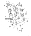
- a cutoff roll system 10 which employs a preferred embodiment of the present invention.
- the present invention can be applied in many other applications to achieve similar advantages, such as for perforation, embossing, folding, or other types of rolls, for forced air systems in rolls (rather than vacuum systems in rolls), and for controlling actuation of blades, bars, inking or gluing devices, or virtually any other type of element or apparatus on a roll which is to be selectively operated or actuated.
- Such conventional elements and apparatuses can be actuated directly by fluid or gas pressure or vacuum, or in conjunction with well-known electrical and/or mechanical systems or devices.
- retractable blades 18 upon the cutoff roll 12 can be actuated directly by air, fluid, or vacuum pressure, or can be moved by one or more bladders which underlie the blades 18 and which themselves are responsive to such pressure by extending or retracting the blades 18.
- the terms "cut”, “cutting” and “cutoff” encompass without limitation a cut, perforation, tear, rupture or break in the web 22, regardless of shape, size or continuity of the cut, perforation, tear, rupture or break.
- the cutoff roll system 10 illustrated in the figures preferably comprises a vacuum assisted cutoff roll 12 and a cutoff bedroll 14.
- the cutoff roll 12 includes a plurality of vacuum apertures 16 and a plurality of selectively actuatable blades 18.
- Each blade 18 is preferably actuatable between a retracted position in which the blade does not cut a passing web 22 and an extended position in which the blade can cut the passing web 22.
- numerous conventional systems and devices exist for controlling the actuation of retractable blades.
- the blades can be controlled by pressurized air or fluid (such as by the same vacuum system described below and used for holding the web 22 against the surface of the cutoff roll 12), by electro-mechanical systems employing solenoids, electromagnets and the like, by mechanical devices employing hydraulic or air-actuated bladders, by direct air or fluid pressure devices, etc.
- pressurized air or fluid such as by the same vacuum system described below and used for holding the web 22 against the surface of the cutoff roll 12
- electro-mechanical systems employing solenoids, electromagnets and the like
- mechanical devices employing hydraulic or air-actuated bladders
- direct air or fluid pressure devices etc.
- the cutoff bedroll 14 preferably includes a plurality of anvils 20 such that, as the cutoff roll 12 rotates, the web 22 is periodically cut between the actuated blades 18 upon the cutoff roll 12 and the anvils 20 upon the cutoff bedroll 14. Cutoff bedrolls and anvils 20 are well known to those skilled in the art and are not therefore described further herein.
- the vacuum apertures 16 are preferably arranged in a plurality of rows 17 running longitudinally along the cutoff roll 12. Blades 18 are mounted in blade receiving regions 19 located between rows 17 of the vacuum apertures 16 (only one blade 18 being shown in FIG. 2 ).
- the vacuum apertures 16 are conventional and can be arranged in a large number of ways. Although preferably the vacuum apertures 16 are arranged in rows which alternate with cutoff blades 18 on the cutoff roll 12, the apertures 16 can be in multiple rows between the cutoff blades 18, can be patterned in a grid or screen form between cutoff blades 18, and can be in the form of round holes, slots or any other aperture shapes between the cutoff blades 18.
- Vacuum assisted cutoff rolls of this type are well known in the art as disclosed in United States Letters Patent No. 4,494,741 issued to Fischer et al. Vacuum (from one or more vacuum generators or a vacuum source) is preferably supplied to a valve 26 located at the end of the cutoff roll 12, and more preferably to valves 26 located on both ends 13 of the cutoff roll 12. More specifically, each valve 26 preferably has a vacuum inlet 24 maintaining fluid communication between the valves 26 and the vacuum generators or vacuum source. Each of the valves 26 can be fixed to a support frame (not shown) for the cutoff roll 12 by spring loaded studs in the manner disclosed in the Fischer Patent.
- the valves 26 distribute vacuum to vacuum lines 27 running within the cutoff roll 12, and thereby to the vacuum apertures 16 in the cutoff roll 12.
- the term "lines” as used herein refers to a structure linking the valves 26 to the vacuum apertures 16 in the cutoff roll 12, and does not indicate or imply any particular shape or size of the structure.
- the lines 27 can be virtually any shape and size capable of establishing fluid communication between the valves 26 and the vacuum apertures 16, and can extend in virtually any manner within the cutoff roll 12 to do so.
- the vacuum lines 27 have a round cross-sectional shape, are straight, and extend longitudinally from the ends 13 of the cutoff roll 12 beneath and to each vacuum aperture 16 in a row of vacuum apertures 16 as best shown in FIG. 2 .
- vacuum is selectively supplied to the vacuum apertures 16 through a manifold arrangement similar to the manner described in the Fischer Patent, hereby incorporated by reference insofar as it relates to the vacuum manifold system and cutoff system disclosed therein.
- Each vacuum valve 26 preferably defines a vacuum chamber 21, shown partially broken away in FIG. 2 .
- the vacuum chamber 21 is generally annular in shape in order to minimize the amount of vacuum necessary for operation of the present invention.
- the vacuum chamber 21 in each vacuum valve 26 can take any shape capable of maintaining fluid communication through the vacuum valve 26 to each of the vacuum lines 27.
- equally spaced inlets 16a in the ends 13 of the cutoff Toll 12 connect the vacuum chambers 21 to each of the vacuum lines 27.
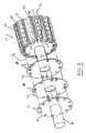
- the vacuum valve 26 further includes a set of disks 30, 32 and 34 (see FIG. 3 ) which provide a manifold allowing controlled and selective supply of the vacuum to the vacuum inlets 16a, vacuum lines 27, and vacuum apertures 16 as will be discussed below.
- the disks 30, 32 and 34 are preferably located within the vacuum valves 26 adjacent to the ends 13 of the cutoff roll 12 as shown in FIG. 3 , with disk 34 positioned adjacent to the end 13 of the cutoff roll 12 and disk 32 located between disk 30 and disk 34.
- the disks 30, 32, 34 are each preferably flat, round, plate-shaped elements secured to the ends 13 of the cutoff roll 12. However, the disks 30, 32, 34 can instead be any shape and thickness desired, and need not resemble a disk at all.
- disks having other shapes and dimensions may be heavier or more difficult to balance than the preferred round, flat, plate-shaped disks illustrated, such other disks are equally capable of covering or uncovering selected inlets 16a and vacuum lines 27 via a number of disk apertures (in the manner discussed below) to accomplish the functions of the present invention. These other disk types therefore fall within the spirit and scope of the present invention.
- Disks 30, 32, 34 are each preferably secured in a conventional manner to the end 13 of the cutoff roll 12 for rotation therewith. However, disks 32 and 34 can preferably be rotated to change the angular relationship of disks 32 and 34 with respect to disk 30, which is preferably fixed for rotation with cutoff roll 12. Most preferably therefore, disks 30, 32, 34 are conventionally mounted upon shafts 35 extending from the ends 13 of the cutoff roll 12. To permit adjust of the angular relationship of disks 32 and 34 with respect to disk 30 and to prevent accidental adjustment of the disks, elastomeric gaskets (not shown) can be sandwiched between the disks to provide frictional resistance to turning of the disks 32, 34 by rotational forces generated during normal system operation.
- the disks 32, 34 can be releasably fastened to the shaft 35, to the fixed disk 30, and/or to the end 13 of the cutoff roll 12 by any conventional releasable fastener.
- setscrews, bolts, or other fasteners can be passed axially through the disks 32, 34 into the fixed disk 30 and/or the end 13 of the cutoff roll 12 (or vice versa), and can be loosened to permit rotational adjustment of either disk 32, 34 and then tightened to secure the relative positions of the disks 30, 32, 34.
- Other conventional releasable fasteners include spring detents located between the disks 32, 34 and the fixed disk 30 and/or the end 13 of the cutoff roll 12, clips securing the disks 32, 34 to the fixed disk 30 and/or the end 13 of the cutoff roll 12, etc.
- the disks 32, 34 can be keyed or mounted in any well known fashion to conventional bushings which themselves can be loosened and tightened to adjust the rotational angle of the disks 32, 34.
- Even more advanced forms of releasable securement methods are possible, such as by electromagnets located upon or embedded within the disks 30, 32, 34, and/or the end 13 of the cutoff roll 12 and controllable manually or via a conventional controller to release the disks 32, 34 for angular adjustment.
- the disks 32, 34 can even be separately controlled for rotation by one or more motors moving the disks in a conventional manner (e.g., by two or more telescoping shafts each secured to one of the two disks 32, 34 and each separately powered by a different motor, one or more powered gear assemblies meshing with gear teeth on the edges of the disks 32, 34 to rotate the disks 32, 34 with the cutoff roll 12, etc.).
- the disks 30, 32, 34 are normally secured for rotation with the cutoff roll 12, but disks 32, 34 are adjustable manually or automatically to change their angular orientation with respect to the fixed disk 30.
- adjustment is performed automatically, such adjustment can be performed via one or more control devices such as a programmable logic controller, a computer, a microcontroller interface, and the like.
- control devices such as a programmable logic controller, a computer, a microcontroller interface, and the like.
- the fixed disk 30 preferably includes a number of apertures 36 numbered, arranged, and spaced to match the inlets 16a in the end 13 of cutoff roll 12, thereby permitting vacuum to communicate between the vacuum valve 26 and the vacuum ports 16.
- the rotationally adjustable disks 32 and 34 also include apertures 37 and 38, one or more of which can be aligned with apertures 36 in the fixed disk 30 and the inlets 16a in the end 13 of the cutoff roll 12 in a number of different angular positions of the disks 32, 34.
- the disks 32, 34 preferably have fewer apertures 37, 38 than the fixed disk 30.
- disks 32, 34 having more apertures 37, 38 work well provided that when apertures in the disks 32, 34 are to be blocked in various predefined positions of the disks (described in more detail below), such apertures 32, 34 are fully blocked to close fluid communication through such apertures 32, 34.
- the disks 32, 34 are spaced such that, when the disks 32, 34 are rotated to predefined positions relative to one another, to the fixed disk 30, and to the cutoff roll 12, the disks 32, 34 selectively prevent vacuum from being extended from the vacuum valve 26 to the vacuum inlets 16a, vacuum lines 27, and vacuum ports 16 corresponding to those vacuum lines 27.
- the disks 32 and 34 thereby selectively connect and disconnect the vacuum ports 16 to the vacuum source or vacuum generator (not shown).
- the rotatable disks 32 and 34 can therefore provide a number of different activation configurations for the vacuum lines 27 and vacuum ports 16 in the cutoff roll 12.
- the cutoff roll 12 includes a plurality of blades, each disposed in a mounting region 19 preferably located between rows of vacuum apertures 16.
- the blades 18 are mounted in the cutoff roll 12 as required by the selected cut lengths, and are held in position upon the cutoff roll 12 in a conventional manner, such as by spring clips or other known devices. Actuation (e.g., extension or retraction) of the blades 18 is performed in a manner discussed above, and can be controlled either manually or automatically in ways well known to those skilled in the art, such as by a programmable logic controller, a computer, a microcontroller interface, and the like.
- vacuum is selectively applied to the vacuum apertures 16 in a manner discussed below such that one row of vacuum apertures 16 is activated between adjacent pairs of selected blades 18.
- the activated vacuum apertures 16 therefore maintain cut portions of the web upon the cutoff roll 12 until the cut portions are passed to downstream equipment and/or operations.
- the blades 18 can be periodically or occasionally indexed. In other words, blades 18 which have been actuated to their extended cutting positions for a period of time can be retracted and other blades in their retracted positions can be extended to continue cutting operations on the passing web 22. In order to continue the same type of cutting operations (i.e., to keep the same spacing between cuts on the web 22), the blades 18 being extended should be spaced apart and arranged upon the cutoff roll 12 in the same manner as the blades 18 being retracted. Of course, if a new cut length is to be made in the passing web 22, the blades 18 being extended will be spaced or numbered and spaced differently than those being retracted. In any case, preferably none of the blades 18 that have just been used and are being retracted are the same as those being extended, thereby avoiding excessive wear on any one blade.
- each blade 18 being extended is preferably located the same distance and angular direction from a respective blade 18 being retracted. Repeated blade indexing in this manner therefore more evenly distributes wear across all of the blades 18.
- An example of this type of blade indexing is described with reference to FIG. 4 .
- extended blades 18 in positions 12, 3, 6, and 9 are retracted, while retracted blades 18 in positions 1, 4, 7, and 10 are extended. Because the blades 18 are equally spaced, the cut length in the passing web 22 will remain the same as the blades 18 are indexed around the circumferences of the cutoff roll 12 in this manner. Also, because none of the blades 18 being retracted are the same as those being extended, excessive blade wear on any particular blade is avoided. In another index of the blades 18, preferably blades 18 in positions 1, 4, 7, and 10 are retracted, while retracted blades 2, 5, 8, and 11 are extended.
- FIGS. 4-6 illustrate another form of blade indexing, in which the cut length in the passing web 22 is changed.
- the cutoff roll 12 includes twelve blades 18 with adjacent blades 18 being separated from each other by a distance equal to thirty degrees of the circumference of the cutoff roll 12.
- four of the blades 18 located at four equally spaced circumferential positions on the cutoff roll 12 are in their extended cutting positions. This extended blade arrangement is shown in FIG.
- the blades 18 at the 0, 120, and 240 degrees positions would be extended as indicated by asterisks (*) in FIG. 5 . Therefore, the blade 18 at the 0 degree circumferential position would be employed to make cuts in both cases: where three equal cuts in the web 22 are desired and where four equal cuts in the web 22 are desired. Accordingly, the blade 18 at the 0 degree circumferential position would be subject to significantly more wear than other blades 18 in the system 10, and would require more frequent maintenance and replacement than the other blades.
- the blades 18 can be indexed to the three-cut configuration shown in FIG. 6 .
- Similar indexing can be performed to a three-cut configuration with blades cutting at the 2, 6, and 10 o'clock positions for a period of time, followed by indexing to blades at the 3, 7, and 11 o'clock positions for a period of time, and then followed by indexing back to the configuration illustrated in FIG. 5 . Therefore, even though changing blade configuration from one length of cut to another length of cut can require multiple uses of the same blade or blades 18 in both cut lengths, continued indexing such as that just described in the present invention will minimize excessive wear on any one blade 18.
- blade indexing can occur when the desired cut length in the web of material passing the cutoff roll 12 is changed.
- blade indexing can be performed at other times to more evenly distribute blade wear across the blades.
- blade indexing preferably occurs automatically (e.g., by an electronic controller) at regular time intervals or cutoff roll 12 rotations.
- blade indexing can be performed each time the parent rolls of web material fed into the system 10 are changed. Such blade indexing distributes blade wear and thereby increases operation time between required maintenance shutdowns.
- a number of vacuum apertures 16 are preferably located between each pair of adjacent blades 18 on the cutoff roll 12.
- suction is applied through these vacuum apertures 16 by opening corresponding vacuum lines 27 to a source of vacuum or a vacuum generator, that portion of the web of material beside the vacuum apertures 16 is held to the surface of the cutoff roll 12.
- the portion of the web 22 is held to the roll before, during, and after the passing web 22 is cut by the blades 18 on either side of the web portion.
- one row of vacuum apertures 16 is centrally located between each pair of adjacent blades 18 on the cutoff roll 12, and is capable of holding (via suction) a web 22 lying across the vacuum apertures 16 during cutting operations by the adjacent blades 18. Because the twelve blades 18 on the cutoff roll 12 are equally spaced in the preferred embodiment shown, the rows of vacuum apertures 16 on the cutoff roll 12 are also equally spaced around the circumference of the cutoff roll 12, and are therefore separated from each other by approximately 30 degrees. In this configuration, one, two, three, four, six, or twelve equal cuts can be provided in the web 22 as the web 22 passes between the cutoff roll 12 and the cutoff bedroll 14 for each rotation of the cutoff roll 12.
- the same number of blades 18 must be spaced equally around the circumference of the cutoff roll 12 as follows: one blade produces one equally-spaced cut per cutoff roll rotation, two blades spaced 180 degrees apart produce two equally-spaced cuts per cutoff roll rotation, three blades spaced 120 degrees apart produce three equally-spaced cuts per cutoff roll rotation, four blades spaced 90 degrees apart produce four equally-spaced cuts per cutoff roll rotation, six blades spaced 60 degrees apart produce six equally-spaced cuts per cutoff roll rotation, and twelve blades spaced 30 degrees apart produce twelve equally-spaced cuts per cutoff roll rotation. Because systems 10 which can produce 3, 4, and 6 equally-spaced cuts per cutoff roll rotation are most desirable, a valve arrangement configured to produce vacuum only in these three blade configurations will be discussed by way of example only.
- At least one row of vacuum ports 16 is preferably activated (i.e., open to the vacuum source or vacuum generator) between each pair of extended blades 18.
- activated i.e., open to the vacuum source or vacuum generator
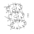
- selection of the rows of vacuum apertures 16 to which vacuum is to be supplied is performed by rotating the disks 32 and 34 described above to provide the proper vacuum configuration as will now be described with reference to FIGS. 7-9 .
- fixed disk 30 preferably includes twelve apertures 36a-361
- disk 32 includes ten apertures 37a-37j
- disk 34 includes eleven apertures 38a-38k.
- FIG. 7 illustrates a set of disks 30, 32, 34 each having a set of apertures 36, 37, 38, respectively, which are arranged such that in a number of different relative positions with respect to one another, 3, 4, and 6 vacuum lines 27 are opened to the vacuum source or generator. It should be noted that the aperture arrangement shown in each of the disks 30, 32, 34 is only one of several aperture arrangements possible for each disk 30, 32, 34 which can be employed to achieve the same function just described. In the disk alignment illustrated in FIG.
- disks 32 and 34 are rotationally adjusted so that apertures 37a and 38a are aligned with aperture 36a of disk 30, apertures 37c and 38d are aligned with aperture 36d of disk 30, apertures 37f and 38g are aligned with aperture 36g of disk 30, and apertures 37h and 38j are aligned with aperture 36j of disk 30.
- aperture 36b overlies solid region 37x of disk 32, such that the supply of vacuum to the row of vacuum apertures 16 aligned with aperture 36b is blocked. With this configuration, vacuum will be supplied to only those vacuum inlets 16a, lines 27, and corresponding vacuum apertures 16 which are aligned with apertures 36a, 36d, 36g, and 36j of disk 30 (each of which are equally spaced 90 degrees apart).
- FIG. 8 illustrates the alignment of the disks 30, 32 and 34 to provide vacuum to vacuum inlets 16a, vacuum lines 27, and corresponding vacuum apertures 16 for a configuration in which three cuts are made in the web 22 per cutoff roll rotation.
- disks 32 and 34 are rotationally adjusted with disk 32 being rotated fifteen degrees counterclockwise and disk 34 being rotated fifteen degrees clockwise from the positions shown in FIG. 7 . Consequently, apertures 37b and 38b are aligned with aperture 36b of disk 30, apertures 37e and 38e are aligned with aperture 36f of disk 30, and apertures 37i and 38i are aligned with aperture 36j of disk 30.
- aperture 36a overlies solid region 37y of disk 32 so that the supply of vacuum to the row of vacuum apertures 16 aligned with aperture 36a is blocked. Also, although aperture 37d is aligned with aperture 36d in disk 30, the solid region 38x blocks the supply of vacuum to the row of vacuum apertures 16 aligned with aperture 36d.
- FIG. 9 illustrates the alignment of the disks 30, 32 and 34 to provide vacuum to vacuum inlets 16a, vacuum lines 27, and corresponding vacuum apertures 16 for a configuration in which six cuts are made in the web 22 per cutoff roll rotation.
- disks 32 and 34 are rotationally adjusted with the position of disk 32 being unchanged and the position of disk 34 being rotated fifteen degrees counterclockwise from its position in FIG. 8 .
- apertures 37b and 38c are aligned with aperture 36b of disk 30
- apertures 37d and 38d are aligned with aperture 36d of disk 30
- apertures 37e and 38f are aligned with aperture 36f of disk 30
- apertures 37g and 38h are aligned with aperture 36h of disk 30
- apertures 37i and 38j are aligned with aperture 36j of disk 30
- apertures 37j and 38k are aligned with aperture 361 of disk 30.
- Apertures 36a, 36c, 36e, 36g, 36i and 36k overlie solid portions of disk 32.
- the apertures 37a-37j of disk 32 and the apertures 38a-38k of disk 34 are each spaced apart around the axis of the disk 32, 34 by multiples of approximately 15 degrees.
- aperture 37j is spaced approximately 15 degrees from aperture 37a
- aperture 37a is spaced approximately 45 degrees from aperture 37b
- aperture 37b is spaced approximately 45 degrees from aperture 37c
- aperture 37c is spaced approximately fifteen degrees from aperture 37d.
- the apertures 36a-361 of fixed disk 30 are spaced apart from each other by approximately 30 degrees.
- the fixed disk 30 is preferably dimensioned such that the separation between adjacent apertures 36 is greater than the circumference of the apertures 36.
- the disks 32 and 34 can be rotationally adjusted relative to the fixed disk 30 to selectively connect vacuum to only a selected number of vacuum lines 27 and associated vacuum apertures 16 between extended blades 18 on the cutoff roll 12.
- vacuum lines 27 can quickly be shut and others can be quickly opened to achieve a desired pattern of extended blades and vacuum aperture rows on the cutoff roll 12.
- valves 26 of the present invention each have three disks 30, 32, 34 as discussed above. Generally, more disks provide more aperture pattern possibilities through the disks to open vacuum to the vacuum inlets 16a, lines 27, and associated vacuum aperture rows. The number of possible aperture patterns will, of course, also depend directly upon the number and size of apertures in the disks, the number and size of vacuum inlets 16a and associated vacuum lines 27 in the roll 12, and the spacing between adjacent apertures in the disks and between adjacent vacuum inlets 16a in the cutoff roll 12.
Landscapes
- Life Sciences & Earth Sciences (AREA)
- Forests & Forestry (AREA)
- Engineering & Computer Science (AREA)
- Mechanical Engineering (AREA)
- Treatment Of Fiber Materials (AREA)
- Advancing Webs (AREA)
- Replacement Of Web Rolls (AREA)
- Paper (AREA)
- Perforating, Stamping-Out Or Severing By Means Other Than Cutting (AREA)
- Blow-Moulding Or Thermoforming Of Plastics Or The Like (AREA)
- Drilling And Boring (AREA)
Claims (8)
- Système pour réaliser des découpes espacées à des distances variables le long d'une toile de matériau, le système comprenant :un rouleau (12) ;une pluralité d'ouvertures de rouleau de vide (16) sur une surface du rouleau (12) ;une pluralité de lames (18) raccordée au rouleau (12), la pluralité de lames (18) étant sélectivement actionnable dans au moins deux dispositions de lame différentes, avec des relations souhaitées dans l'espace relativement à la pluralité d'ouvertures de rouleau sous vide (16) ;une soupape de vide (26) raccordée au rouleau (12) et en communication fluidique avec les ouvertures de rouleau sous vide (16) sur la surface du rouleau (12), la soupape de vide (26) comprenant au moins un premier, un second et un troisième disques (30, 32, 34), chaque disque ayant une pluralité d'ouvertures de disque (36, 37, 38) à travers eux ; etune source de vide en communication fluidique avec la soupape de vide (26), au moins un disque du premier, second et troisième disques (30, 32, 34) étant ajustables pour établir sélectivement la communication fluidique entre au moins une parmi la pluralité d'ouvertures de rouleau sous vide (16) et la source de vide par le biais d'au moins une parmi la pluralité d'ouvertures de disque (36, 37, 38) ;dans lequel les ouvertures de vide (16) sont en communication fluidique avec la soupape de vide (26) par le biais d'une pluralité de lignes de vide (27) dans un rouleau de vide (12), et dans lequel le premier disque (30) comprend une pluralité d'ouvertures égale en nombre à la pluralité de lignes de vide (27) et le second (32) et le troisième disques (34) ont chacun une pluralité d'ouvertures (37, 38) inférieures en nombre aux lignes de vide (27), de sorte que, lorsque le second (32) et le troisième (34) disques sont mis en rotation, les lignes de vide choisies (27) sont bloquées et ouvertes en fonction de l'alignement des ouvertures (37, 38) dans le second et le troisième disques (32, 34).
- Système selon la revendication 1, dans lequel ledit au moins un disque (30, 32, 34) est monté pour tourner relativement au rouleau de vide (12) et dans lequel ledit au moins un disque (30, 32, 34) est ajustable pendant la rotation.
- Système selon la revendication 1, dans lequel chacune de la pluralité des lames (18) actionnées est située dans la même direction et à la même distance d'une lame actionnée correspondante (18).
- Système selon la revendication 1, dans lequel la pluralité de lames (18) est espacée de manière équidistante autour d'une circonférence du rouleau (12).
- Système selon la revendication 1, comprenant en outre un disque fixe (30) ayant une pluralité d'ouvertures de disque fixes (36), ledit au moins un disque (32, 34) étant ajustable relativement au disque fixe (30) afin d'établir sélectivement une communication fluidique entre au moins une parmi la pluralité des ouvertures de rouleau de vide (16) et la source de vide, par le biais d'au moins une parmi la pluralité d'ouvertures de disque (37, 38) et d'au moins une parmi la pluralité d'ouvertures de disques fixes (36).
- Système selon la revendication 1, dans lequel la pluralité de lignes de vide (27) comprend douze lignes de vide (27), la pluralité des lames (18) comprend douze lames et le premier, le second et le troisième disques (30, 32, 34) contiennent des ouvertures (36, 37, 38), de sorte que le premier, le second et le troisième disques (30, 32, 34) sont disposés de manière à tourner pour fournir trois lignes de vide (27) en communication fluidique avec la source de vide espacées de cent-vingt degrés, quatre lignes de vide (27) en communication fluidique avec la source de vide, espacées de quatre-vingt-dix degrés, et six lignes de vide (27) en communication fluidique avec la source de vide espacées de trente degrés.
- Système selon la revendication 6, dans lequel le premier disque (30) a des ouvertures (36) espacées de trente degrés, et le second (32) et le troisième disques (34) ont chacun des ouvertures (37, 38) espacées par incréments de quinze degrés, de sorte que, lorsque le second (32) et le troisième disques (34) sont tournés par incréments de quinze degrés, une pluralité d'ouvertures (37, 38) dans le second et le troisième disques (32, 34) sont bloquées par le premier disque (30).
- Système selon la revendication 1, dans lequel les ouvertures de rouleau sous vide choisies (16), placées en communication fluidique avec la source de vide, sont égales en nombre aux lames (18) actionnées sur le rouleau de vide (12) et dans lequel les ouvertures de rouleau sous vide choisies (16) sont positionnées sur le rouleau de vide (12) pour retenir des feuilles coupées individuelles de la toile sur le rouleau de vide (12) jusqu'à ce que les feuilles soient transférées du rouleau de vide (12).
Priority Applications (2)
| Application Number | Priority Date | Filing Date | Title |
|---|---|---|---|
| EP10182904A EP2308672B1 (fr) | 1999-07-13 | 2000-07-13 | Rouleau assiste par dépression et procédé associé |
| EP10182905A EP2311631A1 (fr) | 1999-07-13 | 2000-07-13 | Rouleau assisté par dépression et procédé associé |
Applications Claiming Priority (3)
| Application Number | Priority Date | Filing Date | Title |
|---|---|---|---|
| US353474 | 1994-12-09 | ||
| US09/353,474 US6296601B1 (en) | 1999-07-13 | 1999-07-13 | Vacuum assisted roll apparatus and method |
| EP00948654A EP1216143B1 (fr) | 1999-07-13 | 2000-07-13 | Rouleau assiste par depression et procede associe |
Related Parent Applications (2)
| Application Number | Title | Priority Date | Filing Date |
|---|---|---|---|
| EP00948654.9 Division | 2000-07-13 | ||
| EP00948654A Division EP1216143B1 (fr) | 1999-07-13 | 2000-07-13 | Rouleau assiste par depression et procede associe |
Related Child Applications (3)
| Application Number | Title | Priority Date | Filing Date |
|---|---|---|---|
| EP10182904A Division EP2308672B1 (fr) | 1999-07-13 | 2000-07-13 | Rouleau assiste par dépression et procédé associé |
| EP10182905.9 Division-Into | 2010-09-29 | ||
| EP10182904.2 Division-Into | 2010-09-29 |
Publications (2)
| Publication Number | Publication Date |
|---|---|
| EP1514677A1 EP1514677A1 (fr) | 2005-03-16 |
| EP1514677B1 true EP1514677B1 (fr) | 2010-12-15 |
Family
ID=23389280
Family Applications (4)
| Application Number | Title | Priority Date | Filing Date |
|---|---|---|---|
| EP10182904A Expired - Lifetime EP2308672B1 (fr) | 1999-07-13 | 2000-07-13 | Rouleau assiste par dépression et procédé associé |
| EP00948654A Expired - Lifetime EP1216143B1 (fr) | 1999-07-13 | 2000-07-13 | Rouleau assiste par depression et procede associe |
| EP04027390A Expired - Lifetime EP1514677B1 (fr) | 1999-07-13 | 2000-07-13 | Rouleau assiste par depression et procédé associé |
| EP10182905A Withdrawn EP2311631A1 (fr) | 1999-07-13 | 2000-07-13 | Rouleau assisté par dépression et procédé associé |
Family Applications Before (2)
| Application Number | Title | Priority Date | Filing Date |
|---|---|---|---|
| EP10182904A Expired - Lifetime EP2308672B1 (fr) | 1999-07-13 | 2000-07-13 | Rouleau assiste par dépression et procédé associé |
| EP00948654A Expired - Lifetime EP1216143B1 (fr) | 1999-07-13 | 2000-07-13 | Rouleau assiste par depression et procede associe |
Family Applications After (1)
| Application Number | Title | Priority Date | Filing Date |
|---|---|---|---|
| EP10182905A Withdrawn EP2311631A1 (fr) | 1999-07-13 | 2000-07-13 | Rouleau assisté par dépression et procédé associé |
Country Status (9)
| Country | Link |
|---|---|
| US (3) | US6296601B1 (fr) |
| EP (4) | EP2308672B1 (fr) |
| AU (1) | AU6212400A (fr) |
| BR (1) | BR0012426A (fr) |
| CA (1) | CA2379377A1 (fr) |
| DE (2) | DE60018953T2 (fr) |
| ES (1) | ES2228291T3 (fr) |
| MX (1) | MXPA02001357A (fr) |
| WO (1) | WO2001003913A1 (fr) |
Families Citing this family (62)
| Publication number | Priority date | Publication date | Assignee | Title |
|---|---|---|---|---|
| US20030092551A1 (en) * | 2001-11-14 | 2003-05-15 | Roland Boss | Methods and apparatus for scoring and trimming imaged sheet media |
| DE50111062D1 (de) | 2001-12-19 | 2006-11-02 | Windmoeller & Hoelscher | Messerschlitzabdeckung an einer schneid- und transportwalze |
| US11230453B2 (en) * | 2003-02-18 | 2022-01-25 | Körber Tissue Fold S.R.L. | Roller for conveying a web or sheet of paper in paper converting machines and conveying method thus obtained |
| CA2484888C (fr) * | 2003-10-16 | 2010-08-31 | Fpna Acquisition Corporation | Ensemble sous vide haut volume reglable pour un rouleau dans une machine d'entrepliage |
| JP4745061B2 (ja) * | 2004-02-05 | 2011-08-10 | 株式会社瑞光 | ウエブの加工装置 |
| US8417374B2 (en) | 2004-04-19 | 2013-04-09 | Curt G. Joa, Inc. | Method and apparatus for changing speed or direction of an article |
| US20050230037A1 (en) | 2004-04-20 | 2005-10-20 | Curt G. Joa, Inc. | Staggered cutting knife |
| US7638014B2 (en) | 2004-05-21 | 2009-12-29 | Curt G. Joa, Inc. | Method of producing a pants-type diaper |
| US8178025B2 (en) | 2004-12-03 | 2012-05-15 | Georgia-Pacific Consumer Products Lp | Embossing system and product made thereby with both perforate bosses in the cross machine direction and a macro pattern |
| US20060122574A1 (en) * | 2004-12-03 | 2006-06-08 | Fort James Corporation | Multi-panel dispenser napkin |
| US7811403B2 (en) | 2005-03-09 | 2010-10-12 | Curt G. Joa, Inc. | Transverse tab application method and apparatus |
| US20060261120A1 (en) * | 2005-05-03 | 2006-11-23 | Slyne William J | Method and apparatus to continuously separate cut pieces from flexible material |
| US20070161487A1 (en) * | 2006-01-10 | 2007-07-12 | Ryczek Chad L | Apparatus and method for forming a discontinuity in an interfolded stack |
| TWI407740B (zh) * | 2006-03-13 | 2013-09-01 | Nokia Corp | 對話啟始協定多媒體服務之刪除機構 |
| US8016972B2 (en) | 2007-05-09 | 2011-09-13 | Curt G. Joa, Inc. | Methods and apparatus for application of nested zero waste ear to traveling web |
| US9433538B2 (en) | 2006-05-18 | 2016-09-06 | Curt G. Joa, Inc. | Methods and apparatus for application of nested zero waste ear to traveling web and formation of articles using a dual cut slip unit |
| US7780052B2 (en) * | 2006-05-18 | 2010-08-24 | Curt G. Joa, Inc. | Trim removal system |
| US9622918B2 (en) | 2006-05-18 | 2017-04-18 | Curt G. Joe, Inc. | Methods and apparatus for application of nested zero waste ear to traveling web |
| US10456302B2 (en) | 2006-05-18 | 2019-10-29 | Curt G. Joa, Inc. | Methods and apparatus for application of nested zero waste ear to traveling web |
| US8172977B2 (en) | 2009-04-06 | 2012-05-08 | Curt G. Joa, Inc. | Methods and apparatus for application of nested zero waste ear to traveling web |
| US20080047658A1 (en) * | 2006-08-28 | 2008-02-28 | Curt G. Joa, Inc. | Bonding method for continuous traveling web |
| ES2922456T3 (es) | 2007-02-21 | 2022-09-15 | Joa Curt G Inc | Método y aparato de colocación de insertos de transferencia simple |
| US9944487B2 (en) | 2007-02-21 | 2018-04-17 | Curt G. Joa, Inc. | Single transfer insert placement method and apparatus |
| US9550306B2 (en) | 2007-02-21 | 2017-01-24 | Curt G. Joa, Inc. | Single transfer insert placement and apparatus with cross-direction insert placement control |
| US9387131B2 (en) | 2007-07-20 | 2016-07-12 | Curt G. Joa, Inc. | Apparatus and method for minimizing waste and improving quality and production in web processing operations by automated threading and re-threading of web materials |
| US8398793B2 (en) | 2007-07-20 | 2013-03-19 | Curt G. Joa, Inc. | Apparatus and method for minimizing waste and improving quality and production in web processing operations |
| EP2028001B1 (fr) * | 2007-08-20 | 2010-10-13 | Zhongrong Li | Appareil combiné pour l'impression de transfert d'image laser et estampage à froid lithographique |
| US8182624B2 (en) * | 2008-03-12 | 2012-05-22 | Curt G. Joa, Inc. | Registered stretch laminate and methods for forming a registered stretch laminate |
| US7717839B2 (en) | 2008-04-04 | 2010-05-18 | C.G. Bretting Manufacturing Co., Inc. | Multi-path interfolding apparatus |
| EP2308786B1 (fr) * | 2008-05-23 | 2020-04-08 | M T C - Macchine Trasformazione Carta S.r.l. | Structure de machine interstitielle à plis multiples |
| RU2011111395A (ru) * | 2008-08-28 | 2012-10-10 | ДЖОРДЖИЯ-ПЭСИФИК КОНСЬЮМЕР ПРОДАКТС ЭлПи (US) | Сфальцованный листовой материал и совокупность сфальцованных листовых материалов |
| US9409372B2 (en) * | 2008-12-29 | 2016-08-09 | Kimberly-Clark Worldwide, Inc. | Method for perforating tissue sheets |
| US9089453B2 (en) | 2009-12-30 | 2015-07-28 | Curt G. Joa, Inc. | Method for producing absorbent article with stretch film side panel and application of intermittent discrete components of an absorbent article |
| US8460495B2 (en) | 2009-12-30 | 2013-06-11 | Curt G. Joa, Inc. | Method for producing absorbent article with stretch film side panel and application of intermittent discrete components of an absorbent article |
| EP2521646A1 (fr) * | 2010-01-07 | 2012-11-14 | Mohrbach Verpackungsmaschinen GmbH | Procédé et dispositif pour fabriquer des boîtes en papier ou en carton |
| US8696537B2 (en) | 2010-02-16 | 2014-04-15 | C.G. Bretting Manufacturing Co., Inc. | Single-fold interfolding machine with ability to produce off-folded towel or tissue products |
| US8663411B2 (en) | 2010-06-07 | 2014-03-04 | Curt G. Joa, Inc. | Apparatus and method for forming a pant-type diaper with refastenable side seams |
| US9603752B2 (en) | 2010-08-05 | 2017-03-28 | Curt G. Joa, Inc. | Apparatus and method for minimizing waste and improving quality and production in web processing operations by automatic cuff defect correction |
| US9566193B2 (en) | 2011-02-25 | 2017-02-14 | Curt G. Joa, Inc. | Methods and apparatus for forming disposable products at high speeds with small machine footprint |
| US8656817B2 (en) * | 2011-03-09 | 2014-02-25 | Curt G. Joa | Multi-profile die cutting assembly |
| USD684613S1 (en) | 2011-04-14 | 2013-06-18 | Curt G. Joa, Inc. | Sliding guard structure |
| US8852068B2 (en) | 2011-04-21 | 2014-10-07 | C.G. Bretting Manufacturing Co., Inc. | Tube in a tube mechanical folding roll |
| US8820380B2 (en) | 2011-07-21 | 2014-09-02 | Curt G. Joa, Inc. | Differential speed shafted machines and uses therefor, including discontinuous and continuous side by side bonding |
| CA2807809C (fr) | 2012-02-20 | 2019-07-23 | Curt G. Joa, Inc. | Methode de formation de liaisons entre des composants discrets d'articles jetables |
| US9908739B2 (en) | 2012-04-24 | 2018-03-06 | Curt G. Joa, Inc. | Apparatus and method for applying parallel flared elastics to disposable products and disposable products containing parallel flared elastics |
| US9371209B2 (en) | 2012-05-01 | 2016-06-21 | C.G. Bretting Manufacturing Co., Inc. | Single path single web single-fold interfolder and methods |
| US9914234B2 (en) | 2013-02-28 | 2018-03-13 | Kimberly-Clark Worldwide, Inc. | Multilateral cutter |
| US9283683B2 (en) | 2013-07-24 | 2016-03-15 | Curt G. Joa, Inc. | Ventilated vacuum commutation structures |
| USD703711S1 (en) | 2013-08-23 | 2014-04-29 | Curt G. Joa, Inc. | Ventilated vacuum communication structure |
| USD703247S1 (en) | 2013-08-23 | 2014-04-22 | Curt G. Joa, Inc. | Ventilated vacuum commutation structure |
| USD703248S1 (en) | 2013-08-23 | 2014-04-22 | Curt G. Joa, Inc. | Ventilated vacuum commutation structure |
| USD704237S1 (en) | 2013-08-23 | 2014-05-06 | Curt G. Joa, Inc. | Ventilated vacuum commutation structure |
| USD703712S1 (en) | 2013-08-23 | 2014-04-29 | Curt G. Joa, Inc. | Ventilated vacuum commutation structure |
| CN203768712U (zh) * | 2013-11-08 | 2014-08-13 | 株式会社瑞光 | 织物切断装置 |
| US9289329B1 (en) | 2013-12-05 | 2016-03-22 | Curt G. Joa, Inc. | Method for producing pant type diapers |
| CA2991328C (fr) | 2015-07-24 | 2021-10-26 | Curt G. Joa, Inc. | Appareil et procedes de commutation a vide |
| US10449746B2 (en) | 2016-06-27 | 2019-10-22 | C. G. Bretting Manufacturing Co., Inc. | Web processing system with multiple folding arrangements fed by a single web handling arrangement |
| EP4082730B1 (fr) * | 2019-12-26 | 2026-05-06 | Panasonic Holdings Corporation | Dispositif de coupe, et dispositif de fabrication d'ensemble d'électrode stratifié |
| JP2021116156A (ja) * | 2020-01-27 | 2021-08-10 | 株式会社リコー | シート吸引装置、シート搬送装置、印刷装置、吸引領域切替装置 |
| US11737930B2 (en) | 2020-02-27 | 2023-08-29 | Curt G. Joa, Inc. | Configurable single transfer insert placement method and apparatus |
| WO2021206591A1 (fr) * | 2020-04-06 | 2021-10-14 | Essity Hygiene And Health Aktiebolag | Procédé de transfert d'un ou plusieurs éléments de matériau de non-tissé découpés pour une utilisation dans un article absorbant |
| CN112454879B (zh) * | 2020-11-02 | 2022-04-29 | 广东正一包装股份有限公司 | 一种用于真空镀膜的真空闸门装置 |
Family Cites Families (94)
| Publication number | Priority date | Publication date | Assignee | Title |
|---|---|---|---|---|
| US940933A (en) * | 1907-07-15 | 1909-11-23 | Carter Crume Co Ltd | Web-folding mechanism. |
| US1053914A (en) * | 1909-07-17 | 1913-02-18 | Frank H Hoberg | Interfolding-machine. |
| US1566079A (en) * | 1922-11-09 | 1925-12-15 | Paper Converting Machine Co | Rotary sheet folder |
| US1602647A (en) * | 1925-11-07 | 1926-10-12 | Carr George Worthington | Master valve |
| US1595992A (en) * | 1925-12-05 | 1926-08-17 | William H Cannard | Interfolding machine |
| US1738354A (en) * | 1926-03-31 | 1929-12-03 | William H Cannard | Web cutting and feeding mechanism |
| US1965523A (en) * | 1929-04-11 | 1934-07-03 | Walter W Macfarren | Rotary flying shear |
| US1886312A (en) * | 1929-11-30 | 1932-11-01 | Nat Paper Products Company | Paper folding machine |
| US2030744A (en) * | 1929-12-09 | 1936-02-11 | Us Rubber Co | Draping machine |
| US2033849A (en) * | 1932-01-13 | 1936-03-10 | Garrett W Mudd | Labeling machine |
| US1974149A (en) * | 1932-06-22 | 1934-09-18 | Paper Converting Machine Co | Sheet-folding machine |
| US1992179A (en) * | 1932-11-01 | 1935-02-26 | Veldown Company Inc | Napkin folding machine |
| US2092952A (en) * | 1934-11-26 | 1937-09-14 | Samuel J Campbell | Paper interfolding machine |
| US2631845A (en) * | 1946-07-30 | 1953-03-17 | Hoe & Co R | Method of printing, folding, and cutting webs to make books |
| US2631846A (en) * | 1947-04-05 | 1953-03-17 | Int Cellucotton Products | Delivery mechanism for tissue interfolding apparatus |
| US2723604A (en) * | 1951-10-26 | 1955-11-15 | E G Staude Mfg Company Inc | Window applying machine |
| US2784784A (en) * | 1953-10-26 | 1957-03-12 | Moore Dry Kiln Company | Clipper machine |
| SE196703C1 (fr) * | 1956-04-07 | 1965-06-15 | Svenska Flaektfabriken Ab | |
| US2872186A (en) * | 1956-07-10 | 1959-02-03 | Levey Fred K H Co Inc | Folder for printing presses |
| US2867438A (en) * | 1956-10-19 | 1959-01-06 | Gen Electric | Paper-stacking device |
| US2929624A (en) * | 1957-05-13 | 1960-03-22 | Jeyes Sanitary Compounds Compa | Apparatus for folding paper and like material |
| US3040777A (en) * | 1959-04-10 | 1962-06-26 | Universal Oil Prod Co | Rotary valve |
| US3069025A (en) * | 1959-07-01 | 1962-12-18 | Berkley Machine Co | Rotary valve for controlling application of suction |
| US3097778A (en) * | 1960-03-18 | 1963-07-16 | Honeywell Regulator Co | Mechanical apparatus |
| US3174428A (en) * | 1960-05-12 | 1965-03-23 | William F Huck | Rotary web processing apparatus |
| DE1179450B (de) * | 1961-03-17 | 1964-10-08 | Richard Winkler | Vorrichtung zum Entfernen der beim Ausschneiden der Fensteroeffnungen entstehenden Abfallstuecke bei Maschinen zur Herstellung von Fensterbriefumschlaegen od. dgl. |
| FR1308591A (fr) * | 1961-07-18 | 1962-11-09 | Bull Sa Machines | Appareil pneumatique d'entraînement de bande |
| US3174372A (en) * | 1962-03-19 | 1965-03-23 | William F Huck | High speed web cutting and delivery machine |
| US3163413A (en) * | 1962-03-28 | 1964-12-29 | Kimberly Clark Co | Cam controlled folding means for papermaking machine |
| GB1042984A (en) * | 1963-11-09 | 1966-09-21 | Deritend Eng Co | Improvements relating to apparatus for use in the manufacture of boxes and the like |
| US3214162A (en) * | 1963-11-15 | 1965-10-26 | Standard Register Co | Gripper support means for rotary folding apparatus |
| US3251256A (en) * | 1964-06-26 | 1966-05-17 | Ibm | Fluid actuated toolholder |
| US3247746A (en) * | 1964-07-02 | 1966-04-26 | Paper Converting Machine Co | Cut-off device |
| US3302503A (en) * | 1964-11-05 | 1967-02-07 | Smithe Machine Co Inc F L | Blank cutting device |
| US3489406A (en) * | 1967-06-07 | 1970-01-13 | Paper Converting Machine Co | Folding apparatus |
| DK112101B (da) * | 1967-06-12 | 1968-11-11 | J Carstens | Apparat til fremføring af ark. |
| US3490762A (en) * | 1967-09-07 | 1970-01-20 | Paper Converting Machine Co | Web-lapping machine |
| US3466029A (en) * | 1967-12-26 | 1969-09-09 | Ibm | Fluid-controlled document transport drum |
| US3494175A (en) * | 1968-09-05 | 1970-02-10 | Us Navy | Pressure commutator mode switch |
| US3587962A (en) * | 1968-12-06 | 1971-06-28 | Agfa Gevaert Ag | Suction cylinder for transmitting a torque |
| US3572681A (en) * | 1969-06-03 | 1971-03-30 | Paper Converting Machine Co | Apparatus for interfolding webs |
| JPS5019971B1 (fr) * | 1970-01-14 | 1975-07-11 | ||
| GB1354486A (en) * | 1970-05-20 | 1974-06-05 | Unilever Ltd | Plate valve |
| US3689061A (en) * | 1970-07-02 | 1972-09-05 | Paper Converting Machine Co | System for folding napkins |
| US3709077A (en) * | 1971-03-01 | 1973-01-09 | Bretting C Mfg Co Inc | Cut-off device |
| US3748187A (en) * | 1971-08-03 | 1973-07-24 | Hughes Aircraft Co | Self-registered doped layer for preventing field inversion in mis circuits |
| US3834689A (en) * | 1972-04-07 | 1974-09-10 | Int Paper Co | Web folding apparatus |
| US3991994A (en) * | 1973-11-05 | 1976-11-16 | Wood Industries, Inc. | Zig-zag web folder apparatus |
| US3948504A (en) * | 1974-03-18 | 1976-04-06 | Motter Printing Press Co. | Method and apparatus for forming and collating printed signatures |
| US4070014A (en) * | 1975-07-28 | 1978-01-24 | Kawanoe Zoki Kabushiki Kaisha | Web folding apparatus |
| CH598110A5 (fr) * | 1975-10-10 | 1978-04-28 | Gretag Ag | |
| US4056057A (en) * | 1976-02-27 | 1977-11-01 | Livermore And Knight Co., Inc. | Vacuum printing cylinder construction |
| DE2652159C3 (de) * | 1976-11-16 | 1981-04-30 | Koenig & Bauer AG, 8700 Würzburg | Räderfalzapparat |
| US4207998A (en) * | 1977-05-16 | 1980-06-17 | Bachofen & Meier, Maschinenfabrik | Vacuum roller |
| US4202542A (en) * | 1977-12-01 | 1980-05-13 | International Business Machines Corporation | Apparatus for handling flexible sheet material of different sizes |
| US4163548A (en) * | 1978-01-23 | 1979-08-07 | Paper Converting Machine Company | Method of lapping webs and product |
| DE2846191C3 (de) * | 1978-10-24 | 1981-08-13 | Koenig & Bauer AG, 8700 Würzburg | Falzapparat für Rollenrotationsdruckmaschinen |
| DE2909006A1 (de) * | 1979-03-08 | 1980-09-11 | Winkler Duennebier Kg Masch | Falzvorrichtung zum erzeugen einer zickzackfoermigen bahn aus papier, zellstoff, tissue o.dgl. werkstoff |
| US4254947A (en) * | 1979-05-30 | 1981-03-10 | C. G. Bretting Mfg. Co. Inc. | Sheet overlap device |
| US4270744A (en) * | 1979-06-15 | 1981-06-02 | C. G. Bretting Mfg. Co. Inc. | Tuckers on mechanical folding rolls |
| US4277010A (en) * | 1980-04-10 | 1981-07-07 | John Dusenbery Company, Inc. | Vacuum roller for transporting a web |
| US4349185A (en) * | 1980-07-21 | 1982-09-14 | Paper Converting Machine Company | Folding apparatus |
| FR2489798A1 (fr) * | 1980-09-05 | 1982-03-12 | Hotchkiss Brandt Sogeme | Dispositif d'empilage d'objets minces et flexibles |
| US4390174A (en) * | 1981-03-18 | 1983-06-28 | Winkler & Dunnebier Maschinenfabrik Und Eisengiesserei Gmbh & Co. | Control head for controlling the suction path of a suction roller |
| US4494741A (en) | 1981-03-20 | 1985-01-22 | John M. Rudolf | Tissue cutting and interfolding apparatus for Z webs |
| DE3241869A1 (de) * | 1982-11-12 | 1984-05-17 | Winkler & Dünnebier, Maschinenfabrik und Eisengießerei GmbH & Co KG, 5450 Neuwied | Vorrichtung zur saugluftsteuerung |
| JPS59113880A (ja) * | 1982-12-22 | 1984-06-30 | 日本たばこ産業株式会社 | 巻たばこ反転装置 |
| US4475730A (en) * | 1983-03-23 | 1984-10-09 | C.G. Bretting Mfg. Co., Inc. | Apparatus for folding and stacking paper products |
| DE3534127A1 (de) * | 1985-09-25 | 1987-04-02 | Mecapec Sa | Verfahren und vorrichtung zum abtrennen von profilwerkstoff |
| US4691908A (en) * | 1986-01-06 | 1987-09-08 | Paper Converting Machine Company | Apparatus for interfolding |
| US4723390A (en) * | 1986-08-11 | 1988-02-09 | Duke Horace W | Tensioning apparatus and methods for plastic packaging |
| US4778441A (en) | 1987-06-16 | 1988-10-18 | C.G. Bretting Manufacturing Co., Inc. | Interfolding machinery improvement |
| US4917665A (en) | 1987-06-16 | 1990-04-17 | C. G. Bretting Manufacturing Co. Inc. | Bedroll interfolding machinery improvement |
| US4785548A (en) * | 1987-08-12 | 1988-11-22 | Celanese Fibers, Inc. | Apparatus and method for accurately setting the cutting gap of a fiber cutting assembly |
| US4949741A (en) * | 1989-01-10 | 1990-08-21 | Vickers, Incorporated | Power transmission |
| US5183252A (en) * | 1989-03-31 | 1993-02-02 | Eastman Kodak Company | Vaccum drum for different sized media |
| DE3923436A1 (de) * | 1989-07-15 | 1991-01-24 | Winkler Duennebier Kg Masch | Verfahren und vorrichtung zum herstellen von papierstapeln |
| US5226870A (en) * | 1990-04-25 | 1993-07-13 | Dowbrands L.P. | Vacuum drum purge method and apparatus |
| DE4106494C1 (fr) * | 1991-03-01 | 1992-05-14 | Dienes Werke Fuer Maschinenteile Gmbh & Co Kg, 5063 Overath, De | |
| DE4126643A1 (de) * | 1991-08-12 | 1993-02-18 | Koenig & Bauer Ag | Trommel zum transportieren und uebergeben von bogen |
| US5297462A (en) * | 1991-10-25 | 1994-03-29 | The Lawrence Paper Company | Slotter wheel mechanism having dynamically retractable slotter blades |
| US5193581A (en) * | 1992-03-17 | 1993-03-16 | Nkk Corporation | Selector valve |
| US5344519A (en) * | 1992-06-30 | 1994-09-06 | Cms Gilbreth Packaging Systems | Apparatus for applying labels onto small cylindrical articles having improved vacuum and air pressure porting for label transport drum |
| DE4235860C2 (de) * | 1992-10-26 | 1998-07-09 | Mann & Hummel Filter | Rohrweiche |
| US5570620A (en) * | 1993-12-22 | 1996-11-05 | Best Cutting Die Company | Panel cutting apparatus |
| US5653671A (en) | 1994-12-30 | 1997-08-05 | Riverwood International Corporation | Carton feeder assembly |
| US5540128A (en) * | 1995-01-27 | 1996-07-30 | Lawrence Paper Company | Selectively retractable slutter blade mechanism with remote activation/deactivation function |
| DE19525343C2 (de) * | 1995-07-12 | 2000-11-09 | Gat Gmbh | Vorrichtung zum Überführen von Fluid zwischen relativ zueinander drehbaren Maschinenteilen |
| DE19526507C2 (de) * | 1995-07-20 | 1999-04-08 | Wifag Maschf | Messerzylinder mit verstellbarem Messerbalken |
| US5755654A (en) * | 1995-10-24 | 1998-05-26 | James River Corporation Of Virginia | Method and apparatus for pinch perforating multiply web material |
| DE19651954A1 (de) * | 1996-12-13 | 1998-06-18 | Bayer Bitterfeld Gmbh | Vorrichtung zum Schneiden einer Streifenverpackung |
| US5970837A (en) * | 1996-12-18 | 1999-10-26 | Johns Manville International, Inc. | Chopper for cutting fiber continuously, and method |
| DE19854844A1 (de) * | 1997-12-24 | 1999-07-01 | Heidelberger Druckmasch Ag | Vorrichtung zur Saugluftsteuerung |
| US6209867B1 (en) * | 1999-08-18 | 2001-04-03 | Hewlett-Packard | Sliding valve vacuum holddown |
-
1999
- 1999-07-13 US US09/353,474 patent/US6296601B1/en not_active Expired - Fee Related
-
2000
- 2000-07-13 DE DE60018953T patent/DE60018953T2/de not_active Expired - Lifetime
- 2000-07-13 MX MXPA02001357A patent/MXPA02001357A/es active IP Right Grant
- 2000-07-13 EP EP10182904A patent/EP2308672B1/fr not_active Expired - Lifetime
- 2000-07-13 AU AU62124/00A patent/AU6212400A/en not_active Abandoned
- 2000-07-13 CA CA002379377A patent/CA2379377A1/fr not_active Abandoned
- 2000-07-13 EP EP00948654A patent/EP1216143B1/fr not_active Expired - Lifetime
- 2000-07-13 DE DE60045397T patent/DE60045397D1/de not_active Expired - Lifetime
- 2000-07-13 WO PCT/US2000/019112 patent/WO2001003913A1/fr not_active Ceased
- 2000-07-13 BR BR0012426-5A patent/BR0012426A/pt active Search and Examination
- 2000-07-13 EP EP04027390A patent/EP1514677B1/fr not_active Expired - Lifetime
- 2000-07-13 ES ES00948654T patent/ES2228291T3/es not_active Expired - Lifetime
- 2000-07-13 EP EP10182905A patent/EP2311631A1/fr not_active Withdrawn
-
2001
- 2001-03-12 US US09/803,856 patent/US6431038B2/en not_active Expired - Fee Related
-
2002
- 2002-08-13 US US10/218,917 patent/US20030045415A1/en not_active Abandoned
Also Published As
| Publication number | Publication date |
|---|---|
| US20010009883A1 (en) | 2001-07-26 |
| EP1216143A4 (fr) | 2002-10-16 |
| WO2001003913A1 (fr) | 2001-01-18 |
| AU6212400A (en) | 2001-01-30 |
| US20030045415A1 (en) | 2003-03-06 |
| EP2308672B1 (fr) | 2012-10-03 |
| EP1216143B1 (fr) | 2005-03-23 |
| ES2228291T1 (es) | 2005-04-16 |
| MXPA02001357A (es) | 2004-09-10 |
| ES2228291T3 (es) | 2005-09-01 |
| DE60018953T2 (de) | 2006-01-12 |
| US6296601B1 (en) | 2001-10-02 |
| DE60018953D1 (de) | 2005-04-28 |
| DE60045397D1 (de) | 2011-01-27 |
| BR0012426A (pt) | 2002-05-21 |
| US6431038B2 (en) | 2002-08-13 |
| EP1216143A1 (fr) | 2002-06-26 |
| EP2311631A1 (fr) | 2011-04-20 |
| EP1514677A1 (fr) | 2005-03-16 |
| EP2308672A1 (fr) | 2011-04-13 |
| CA2379377A1 (fr) | 2001-01-18 |
Similar Documents
| Publication | Publication Date | Title |
|---|---|---|
| EP1514677B1 (fr) | Rouleau assiste par depression et procédé associé | |
| EP1058606B1 (fr) | Dispositif de perforation avec rouleau de perforation a espacement differentiel | |
| JP4563529B2 (ja) | 横断幅を有しかつ無限の長さを有するウェブを複数の使用供給形態へ変換する方法及び装置 | |
| US5297461A (en) | Rotary shear | |
| EP0318174A2 (fr) | Dispositif de coupe rotative | |
| CN108698780B (zh) | 一种用于交织机的吸辊结构 | |
| EP1845048B1 (fr) | Ensemble de pliage et de découpe pour des produits tels que les tissus, les serviettes ou similaires | |
| EP0729910B1 (fr) | Cylindre pour appareil de pliage ainsi qu'un appareil de pliage | |
| RU2095250C1 (ru) | Устройство для изготовления многослойного рукава из бумажных полотен | |
| EP3781506B1 (fr) | Structure de rouleau d'aspiration pour machines de pliage enchevêtré | |
| US5802945A (en) | Needle roller arrangement with several needle rollers for perforating a material web | |
| WO2000006351A1 (fr) | Perforateur pour materiaux du type en bande, dote de moyens de modification de l'intervalle entre des lignes consecutives de perforations | |
| US5159868A (en) | Knife cylinder for processing weblike material | |
| EP2379435B1 (fr) | Machine de pliage à pli unique améliorée et procédé pour celle-ci | |
| EP3475204B1 (fr) | Système de traitement de bande doté de plusieurs dispositifs de pliage alimentés par un seul dispositif de manipulation de bande | |
| US5067698A (en) | Method and apparatus for manufacturing interfolded toweling | |
| US5647277A (en) | Skip-scorer, skip-perforator apparatus for use with printing press systems | |
| US4114869A (en) | Mechanism for effecting interlock of multiple sheet continuous business forms | |
| GB1595096A (en) | Travelling paper web slitter | |
| EP4566577B1 (fr) | Appareil pour traiter des bandes continues en mouvement et machine comprenant cet appareil | |
| US20260097537A1 (en) | Support device for a blade, cutting or perforating device comprising the support device, and machine | |
| EP3272688B1 (fr) | Ensemble de perforateur pour enrouleur de matériau en feuille | |
| DE19507351A1 (de) | Läufer für eine Falteinrichtung sowie Falteinrichtung | |
| JPH0958927A (ja) | 折畳みウエブ積層体の製造方法 |
Legal Events
| Date | Code | Title | Description |
|---|---|---|---|
| PUAI | Public reference made under article 153(3) epc to a published international application that has entered the european phase |
Free format text: ORIGINAL CODE: 0009012 |
|
| PUAF | Information related to the publication of a search report (a3 document) modified or deleted |
Free format text: ORIGINAL CODE: 0009199SEPU |
|
| 17P | Request for examination filed |
Effective date: 20041203 |
|
| AC | Divisional application: reference to earlier application |
Ref document number: 1216143 Country of ref document: EP Kind code of ref document: P |
|
| AK | Designated contracting states |
Kind code of ref document: A1 Designated state(s): DE ES FR GB IT SE |
|
| D17D | Deferred search report published (deleted) | ||
| RAP1 | Party data changed (applicant data changed or rights of an application transferred) |
Owner name: COUTURIER, DENNIS P. Owner name: C.G. BRETTING MANUFACTURING CO., INC. |
|
| R17P | Request for examination filed (corrected) |
Effective date: 20041203 |
|
| AKX | Designation fees paid |
Designated state(s): DE ES FR GB IT SE |
|
| 17Q | First examination report despatched |
Effective date: 20080917 |
|
| GRAP | Despatch of communication of intention to grant a patent |
Free format text: ORIGINAL CODE: EPIDOSNIGR1 |
|
| GRAS | Grant fee paid |
Free format text: ORIGINAL CODE: EPIDOSNIGR3 |
|
| GRAA | (expected) grant |
Free format text: ORIGINAL CODE: 0009210 |
|
| RAP1 | Party data changed (applicant data changed or rights of an application transferred) |
Owner name: C.G. BRETTING MANUFACTURING COMPANY, INC. |
|
| AC | Divisional application: reference to earlier application |
Ref document number: 1216143 Country of ref document: EP Kind code of ref document: P |
|
| AK | Designated contracting states |
Kind code of ref document: B1 Designated state(s): DE ES FR GB IT SE |
|
| REG | Reference to a national code |
Ref country code: GB Ref legal event code: FG4D |
|
| REF | Corresponds to: |
Ref document number: 60045397 Country of ref document: DE Date of ref document: 20110127 Kind code of ref document: P |
|
| PG25 | Lapsed in a contracting state [announced via postgrant information from national office to epo] |
Ref country code: SE Free format text: LAPSE BECAUSE OF FAILURE TO SUBMIT A TRANSLATION OF THE DESCRIPTION OR TO PAY THE FEE WITHIN THE PRESCRIBED TIME-LIMIT Effective date: 20101215 |
|
| PG25 | Lapsed in a contracting state [announced via postgrant information from national office to epo] |
Ref country code: ES Free format text: LAPSE BECAUSE OF FAILURE TO SUBMIT A TRANSLATION OF THE DESCRIPTION OR TO PAY THE FEE WITHIN THE PRESCRIBED TIME-LIMIT Effective date: 20110326 |
|
| PLBE | No opposition filed within time limit |
Free format text: ORIGINAL CODE: 0009261 |
|
| STAA | Information on the status of an ep patent application or granted ep patent |
Free format text: STATUS: NO OPPOSITION FILED WITHIN TIME LIMIT |
|
| 26N | No opposition filed |
Effective date: 20110916 |
|
| REG | Reference to a national code |
Ref country code: DE Ref legal event code: R097 Ref document number: 60045397 Country of ref document: DE Effective date: 20110916 |
|
| PGFP | Annual fee paid to national office [announced via postgrant information from national office to epo] |
Ref country code: GB Payment date: 20120725 Year of fee payment: 13 |
|
| PGFP | Annual fee paid to national office [announced via postgrant information from national office to epo] |
Ref country code: FR Payment date: 20120731 Year of fee payment: 13 Ref country code: IT Payment date: 20120723 Year of fee payment: 13 Ref country code: DE Payment date: 20120727 Year of fee payment: 13 |
|
| GBPC | Gb: european patent ceased through non-payment of renewal fee |
Effective date: 20130713 |
|
| REG | Reference to a national code |
Ref country code: DE Ref legal event code: R119 Ref document number: 60045397 Country of ref document: DE Effective date: 20140201 |
|
| REG | Reference to a national code |
Ref country code: FR Ref legal event code: ST Effective date: 20140331 |
|
| PG25 | Lapsed in a contracting state [announced via postgrant information from national office to epo] |
Ref country code: GB Free format text: LAPSE BECAUSE OF NON-PAYMENT OF DUE FEES Effective date: 20130713 Ref country code: DE Free format text: LAPSE BECAUSE OF NON-PAYMENT OF DUE FEES Effective date: 20140201 |
|
| PG25 | Lapsed in a contracting state [announced via postgrant information from national office to epo] |
Ref country code: IT Free format text: LAPSE BECAUSE OF NON-PAYMENT OF DUE FEES Effective date: 20130713 Ref country code: FR Free format text: LAPSE BECAUSE OF NON-PAYMENT OF DUE FEES Effective date: 20130731 |