EP1515414B1 - Elektromotor - Google Patents
Elektromotor Download PDFInfo
- Publication number
- EP1515414B1 EP1515414B1 EP04291709A EP04291709A EP1515414B1 EP 1515414 B1 EP1515414 B1 EP 1515414B1 EP 04291709 A EP04291709 A EP 04291709A EP 04291709 A EP04291709 A EP 04291709A EP 1515414 B1 EP1515414 B1 EP 1515414B1
- Authority
- EP
- European Patent Office
- Prior art keywords
- terminal
- magnet wire
- brush
- disposed
- tang
- Prior art date
- Legal status (The legal status is an assumption and is not a legal conclusion. Google has not performed a legal analysis and makes no representation as to the accuracy of the status listed.)
- Expired - Lifetime
Links
- 230000009977 dual effect Effects 0.000 claims abstract description 28
- 238000004804 winding Methods 0.000 claims description 41
- 238000000034 method Methods 0.000 claims description 28
- 238000004519 manufacturing process Methods 0.000 claims description 9
- 238000003466 welding Methods 0.000 claims description 5
- 239000004020 conductor Substances 0.000 abstract description 11
- 238000012360 testing method Methods 0.000 description 5
- 238000003475 lamination Methods 0.000 description 4
- WABPQHHGFIMREM-UHFFFAOYSA-N lead(0) Chemical compound [Pb] WABPQHHGFIMREM-UHFFFAOYSA-N 0.000 description 4
- 239000004568 cement Substances 0.000 description 2
- 238000010276 construction Methods 0.000 description 2
- 238000012986 modification Methods 0.000 description 2
- 230000004048 modification Effects 0.000 description 2
- 229910001369 Brass Inorganic materials 0.000 description 1
- RYGMFSIKBFXOCR-UHFFFAOYSA-N Copper Chemical compound [Cu] RYGMFSIKBFXOCR-UHFFFAOYSA-N 0.000 description 1
- 230000015572 biosynthetic process Effects 0.000 description 1
- 239000010951 brass Substances 0.000 description 1
- 239000010960 cold rolled steel Substances 0.000 description 1
- 239000010949 copper Substances 0.000 description 1
- 229910052802 copper Inorganic materials 0.000 description 1
- 238000005520 cutting process Methods 0.000 description 1
- 238000010586 diagram Methods 0.000 description 1
- 238000013100 final test Methods 0.000 description 1
- 239000011521 glass Substances 0.000 description 1
- 238000010438 heat treatment Methods 0.000 description 1
- 238000009434 installation Methods 0.000 description 1
- 238000009413 insulation Methods 0.000 description 1
- 239000012774 insulation material Substances 0.000 description 1
- 210000003734 kidney Anatomy 0.000 description 1
- 239000000463 material Substances 0.000 description 1
- 239000007769 metal material Substances 0.000 description 1
- 239000012811 non-conductive material Substances 0.000 description 1
- 238000013021 overheating Methods 0.000 description 1
- 229920000728 polyester Polymers 0.000 description 1
- 238000005476 soldering Methods 0.000 description 1
- 229920001169 thermoplastic Polymers 0.000 description 1
- 239000004416 thermosoftening plastic Substances 0.000 description 1
Images


Classifications
-
- H—ELECTRICITY
- H02—GENERATION; CONVERSION OR DISTRIBUTION OF ELECTRIC POWER
- H02K—DYNAMO-ELECTRIC MACHINES
- H02K23/00—DC commutator motors or generators having mechanical commutator; Universal AC/DC commutator motors
- H02K23/66—Structural association with auxiliary electric devices influencing the characteristic of, or controlling, the machine, e.g. with impedances or switches
-
- H—ELECTRICITY
- H02—GENERATION; CONVERSION OR DISTRIBUTION OF ELECTRIC POWER
- H02K—DYNAMO-ELECTRIC MACHINES
- H02K11/00—Structural association of dynamo-electric machines with electric components or with devices for shielding, monitoring or protection
- H02K11/20—Structural association of dynamo-electric machines with electric components or with devices for shielding, monitoring or protection for measuring, monitoring, testing, protecting or switching
- H02K11/25—Devices for sensing temperature, or actuated thereby
-
- H—ELECTRICITY
- H02—GENERATION; CONVERSION OR DISTRIBUTION OF ELECTRIC POWER
- H02K—DYNAMO-ELECTRIC MACHINES
- H02K15/00—Processes or apparatus specially adapted for manufacturing, assembling, maintaining or repairing of dynamo-electric machines
- H02K15/30—Manufacture of winding connections
- H02K15/33—Connecting winding sections; Forming leads; Connecting leads to terminals
-
- H—ELECTRICITY
- H02—GENERATION; CONVERSION OR DISTRIBUTION OF ELECTRIC POWER
- H02K—DYNAMO-ELECTRIC MACHINES
- H02K5/00—Casings; Enclosures; Supports
- H02K5/04—Casings or enclosures characterised by the shape, form or construction thereof
- H02K5/14—Means for supporting or protecting brushes or brush holders
- H02K5/143—Means for supporting or protecting brushes or brush holders for cooperation with commutators
- H02K5/148—Slidably supported brushes
-
- H—ELECTRICITY
- H02—GENERATION; CONVERSION OR DISTRIBUTION OF ELECTRIC POWER
- H02K—DYNAMO-ELECTRIC MACHINES
- H02K3/00—Details of windings
- H02K3/46—Fastening of windings on the stator or rotor structure
- H02K3/52—Fastening salient pole windings or connections thereto
- H02K3/521—Fastening salient pole windings or connections thereto applicable to stators only
- H02K3/522—Fastening salient pole windings or connections thereto applicable to stators only for generally annular cores with salient poles
-
- Y—GENERAL TAGGING OF NEW TECHNOLOGICAL DEVELOPMENTS; GENERAL TAGGING OF CROSS-SECTIONAL TECHNOLOGIES SPANNING OVER SEVERAL SECTIONS OF THE IPC; TECHNICAL SUBJECTS COVERED BY FORMER USPC CROSS-REFERENCE ART COLLECTIONS [XRACs] AND DIGESTS
- Y10—TECHNICAL SUBJECTS COVERED BY FORMER USPC
- Y10T—TECHNICAL SUBJECTS COVERED BY FORMER US CLASSIFICATION
- Y10T29/00—Metal working
- Y10T29/49—Method of mechanical manufacture
- Y10T29/49002—Electrical device making
- Y10T29/49009—Dynamoelectric machine
- Y10T29/49011—Commutator or slip ring assembly
Definitions
- the disclosure is generally related to electric motors, and more particularly to a method of assembling an electric motor without a separate lead wire.
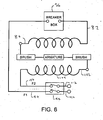
- Prior electric motors have been assembled with a magnet wire that is terminated at a first terminal of a fuse.
- a separate lead wire is attached to the second terminal of the fuse at one end, and to a power switch on its other end. By closing the power switch, current flows across the switch and through the lead wire. If the conductor of the fuse is in tact, the current travels across the conductor and into the magnet wire and the coil.
- the current method is inefficient because two separate wires are necessary, and thus separate steps are required in the manufacture of the electric motor. First a magnet wire must be attached to the fuse. Then, a separate lead wire must be included, with a first end attached to the fuse, and a second end attached to the switch. These separate steps generally require separate operations by machines from at least two work stations. It would be helpful if this procedure of manufacture could be made faster and less expensive. To this aim, in accordance with the present invention the method of making an electric motor has the features of claim 1.
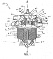
- FIG. 1 is a perspective view of the front of an example of an electric motor.
- FIG. 2 is a perspective view of the rear of the electric motor of FIG. 1 .
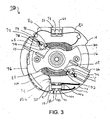
- FIG. 3 is a top view of the electric motor of FIG. 1 .
- FIG. 3A is a sectional view of the electric motor taken along line 3A-3A in FIG. 1 .
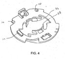
- FIG. 4 is an perspective view of the winding board of the electric motor of FIG. 1 .
- FIG. 5 is an perspective view of the lower housing of the electric motor of FIG. 1 .
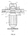
- FIG. 6 is a wiring diagram of the electric motor of FIG. 1 .
- FIG. 7 is a side view of the armature and lower housing of the electric motor of FIG. 1 , prior to assembling the armature in the housing.
- FIG. 8 is a side view of the armature and lower housing of the electric motor of FIG. 1 , upon assembling the armature in the housing.
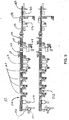
- FIG. 9 is a layout view of the assembly line for the motor of FIG. 1 .
- the motor 10 includes a stator 12, a winding board 14, and a lower housing 16 (shown on the top in FIGS. 1 and 2 ). Supported by the stator 12 and the winding board 14 is a coil 18, including a first pole 20 and a second pole 22. Fastened to the stator 12 is an upper housing 24 (shown on the bottom in FIGS. 1 and 2 ). An armature 26 with a commutator 28 is rotatably mounted within the upper housing 24 and the lower housing 16, and is rotatable about axis A-A, as is known in the art.
- the stator 12 can comprise a series of laminations 30, each of which is an annular plate with a large interior opening.
- the laminations 30 can be made from cold rolled steel, for example SAE 1010 or 1008, and can be welded together via plasma welding, as is known in the art. By stacking several laminations 30, a tubular shape with an exterior annular surface 32 and an interior annular surface 34 is created.
- the interior annular surface 34 also includes a first hook-like protrusion 35 and a second hook-like protrusion 37, each of which project inwardly towards the center axis A-A.
- the first protrusion 35 is used to support the first pole 20, while the second protrusion 37 is used to support the second pole 22, as is commonly known.
- Each of the first protrusion 35 and the second protrusion 37 include pole tips 39 that define kidneys 41.
- the interior annular surface 34 can include insulation 43 to protect and insulate it from the coil 18 as is commonly known in the art.
- the winding board 14 is disposed on the stator 12.
- the winding board 14 is an annular plate with a large interior opening.
- the winding board 14 is made of a non-conductive material, for example a thermoplastic such as a glass-filled polyester, and further includes a first lug 36 and a second lug 38.
- the first lug 36 is used to support the first pole 20 on the end of the motor 10 nearest the lower housing 16.
- the second lug 38 is used to support the second pole 22 on that same end.
- the winding board 14 includes structure to receive and route the wiring of the motor 10 such that current is supplied to the coil 18. Disposed on the winding board 14 is a switch 40 (see FIG. 1 ) that is used to make connections with wiring.
- the switch 40 includes an external terminal 42 that can receive current from an external source.
- the external terminal 42 includes a first block 44 and a second block 46.
- the switch 40 further includes an internal terminal 48 which can deliver current to the motor 10.
- the internal terminal 48 also include a first block 50 and a second block 52.
- Each of the first and second blocks 44, 46, 50, 52 of the internal and external terminals 42, 48 can employ a tang for connection to the wiring of the motor 10.
- a tang is simply a small plate of electrically conductive material with a flap pushed up such that an exposed wire can be crimped between the flap and the plate, to hold it against the plate, thereby providing an electrical connection from the wire to the plate.
- Other connections can be employed such as male-female terminals, sonic welding, or soldering.
- the switch 40 also includes a lever 54 which moves between a first position and a second position. In the first position, electric current can be carried between the external terminal 42 and the internal terminal 48. If the lever 54 is moved to the second position, however, the circuit is opened, and no current can be carried between the external terminal 42 to the internal terminal 48, thus cutting power to the motor 10.
- switches such as three position switches, can likewise be used.
- a fuse 56 disposed on the winding board 14 is a fuse 56. While a fuse is disclosed herein, a circuit breaker could also be used.
- the fuse 56 includes an input terminal 58, an exit terminal 60 and a conductor 62.
- the input terminal 58 and the exit terminal 60 can both use tangs or other structure to connect to the wiring.
- current flows from the input terminal 58 across the conductor 62 and to the exit terminal 60. If a predetermined amount of current crosses the conductor 62, the conductor 62 melted such that the circuit is opened and no current can flow from the input terminal 58 to the exit terminal 60.
- the lower housing 16 is mounted to the winding board 14, and includes structure to receive current from the coil 18 and carry it to and from the armature 26.
- the lower housing 16 may be manufactured from a similar material as the winding board 14.
- the lower housing includes a first brush housing 64 and a second brush housing 66. Disposed within each brush housing 64, 66 is an electrically conductive brush 65, 67 (seen in Fig. 7 and 8 ), which is urged, usually by a springloaded member 69, radially inwardly toward axis of rotation A-A and the armature 26 (See. FIG. 7 and 8 ).
- the brushes 65, 67 transmit the current to the rotating armature 26 through the commutator 28.
- the first dual tang terminal 68 is manufactured from an electrically conductive material, such as brass or copper, and includes a first tang 70 and a second tang 72 configured for the connection of wiring as described earlier.
- the first and second tangs 70, 72 are electrically connected to each other via the conductivity of the terminal 68 itself. Accordingly, a wire connected to the first tang 70 is electrically connected to a wire connected to the second tang 72.
- Fastened to the top of the second brush housing 66 is a second dual tang terminal 74. It can be similar to the first dual tang terminal 68. Of course, other known methods and structure for attaching wire to a terminal can be used.
- the wiring of motor 10 is comprised of a first magnet wire 76 and a second magnet wire 78.
- the first magnet wire 76 is a single wire that forms a first start portion 80, a first coil portion 82, and a first finish portion 84.
- the first magnet wire 76 is attached at a first end 86 to the first block 50 of the internal terminal 48 of the switch 40.
- the first magnet wire 76 is further disposed across the tang of the input terminal 58 of the fuse 56.
- the length of the first magnet wire 76 disposed between the internal terminal 48 of the switch 40 and the input terminal 58 of the fuse 56 is known as the first start portion 80.
- the first magnet wire 76 is attached to the tang of the exit terminal 60 of the fuse 56.
- the first magnet wire 76 is further wrapped many times around the lug 36 of the winding board 14, as shown in Fig. 3 , and the hook like projection of the stator 12 to form the first pole 20.
- the length of the first magnet wire 76 disposed after the fuse 56 and within the first pole 20 is known as the first coil portion 82.
- the first magnet wire 76 extends out of the first pole 20 and is terminated on the first tang 70 of the first dual tang terminal 68 on the first brush housing 64.
- the length of the first magnet wire 76 after the first pole 20 and up to the first dual tang terminal 68 is known as the first finish portion 84.
- the first dual tang terminal 68 includes a first tang 70 and a second tang 72 that are electrically connected to each other through metallic material of the terminal 68 itself.
- a first brush wire 88 has a first end 90 disposed on the second tang 72 of the first dual tang terminal 68, and a second end 92 disposed on the first brush housing 64 (See FIG. 2 ).
- the first brush wire 88 is electrically connected to the first brush 65 slidingly disposed within the first brush housing 64, as is known in the art.
- the first brush 65 is urged forward to the axis of rotation A-A and into physical and electrical contact with the commutator 28 and the armature 26.
- the armature 26 spins around the axis of rotation A-A while in contact with the first brush 65.
- a second brush 67 is disposed within the second brush housing 66 opposite the first brush housing 64.
- the second brush 67 is also urged forward into contact with the armature 26.
- a second brush wire 94 connects the second brush housing 66 to a second tang 100 on the second tang terminal 74.
- the second magnet wire 78 is also single wire that forms a second finish portion 102, a second coil portion 104, and a second start portion 106.
- the second end 108 of the second magnet wire 78 is disposed on the first tang 98 of the second tang terminal 74, and extends downward and is wrapped many times about the second lug 38 in the winding board 14 and the second hooklike protrusion in the stator 12 to form the second pole 22 of the coil.
- the length of the second magnet wire 78 between the second tang terminal 74 and the second pole 22 is known as the second finish portion 102.
- the length of the second magnet wire 78 within the second pole 22 is known as a second coil portion 104.
- the second magnet wire 78 then exits the second pole 22 and is connected to the second block 52 of the internal terminal 48 on the switch 40.
- the length of the second magnet wire 78 between the internal terminal 48 and the second pole 22 is known as a second start portion 106.
- power cords 110 and 112 are fastened to the first and second blocks 44, 46 of the external terminal 42 on the switch 40.
- the power cords 110 and 112 provide electric current to the motor 10.
- the first magnet wire 76 is a single, unitary wire upon installation in the motor 10.
- the first magnet wire 76 is attached to the first block 50 of the internal terminal 48, is disposed across both the input terminal 58 and the exit terminal 60 of the fuse 56, is wrapped about the first lug 36 of the winding board 14 to form the first pole 20 of the coil 18, then terminates on the first dual tang terminal 68.
- the first magnet wire 76 is severed in between the input terminal 58 and the exit terminal 60 such that the wire itself cannot carry current, and any current that flows to the coil 18 flows through the conductor 62 for the protection of the motor 10.
- the winding board 14 is adapted to route the first magnet wire 76 and the second magnet wire 78 about the winding board 14.
- a first clip 114, a second clip 116, and a third clip 118 are disclosed. However, more or less clips could be used to route the wire.
- the energized armature 26 is also in contact with the second brush 67 inside the second brush housing 66.
- Current flows through the second brush 67 and into the second brush wire 94 to the second dual tang terminal 74.
- Current then flows from the second start wire 102 into the second coil wire 104, thereby energizing the second pole 22.
- Finally current flows through the second finish wire 106 out to the internal terminal 48 of the switch 40.
- a current flowing through the first pole 20 and the second pole 22 generates a magnetic field.
- the armature 26, with current flowing through it, is induced to rotate about the axis A-A.
- Fig. 9 discloses a production floor 150 including a pair of assembly lines 152 with several work stations which work together to manufacture the described electric motor 10. While two assembly lines 152 are depicted, they are identical and each one can independently manufacture the motor 10. The motor 10 is transferred from one station to the next via a pallet conveyor as is known in the art.
- the laminations 30 are automatically stacked and welded together. Torroid sensing of weld current is used to insure welds are occurring.
- an automatic load/unload machine automatically forms, cuts to length, and inserts insulation material into the stator 12.
- the winding board 14 is placed on the stator 12.
- the first and second magnet wires 76, 78 are wound about the stator 12 and the winding board 14 to create the first pole 20 and the second pole 22.
- the formation of the poles 20, 22 about the winding board 14 and the stator 12 helps to secure the winding board 14 to the stator 12.
- both the switch 40 and the fuse 56 are disposed on the winding board 14.
- the switch 40 is disposed on the winding board 14 in the off position.
- the first magnet wire 76 is disposed on the first block 50 of the internal terminal 48 of the switch 40 and across the input terminal 58 and the exit terminal 60 of the fuse 56.
- the second magnet wire 78 is disposed on second block 52 of the internal terminal 48 of the switch 40.
- the tang terminals of the fuse 56 and the switch 40 and the first magnet wire 76 disposed therein are fused using an electrode weld.
- the lower housing 16 is assembled. This includes placing the dual-tang terminals 68, 74 on the lower housing 16, inserting a bearing 120 into the lower housing 16, inserting the first and second brushes 65, 67 into the brush housings 64, 66, and connecting the brush wires 88, 94 from the second tangs 72, 100 of the dual tang terminals 68, 74 to the brush housings 64, 66. The lower housing 16 is further placed on the winding board 14.
- the ninth station 170 is similar to the sixth station 164 in that it is also a wire placing station. At the ninth station 170, the first and second magnet wires 76, 78 are disposed on the first tangs 70, 98 of the dual tang terminals 68, 74 on the lower housing 16.
- the tenth station 172 is similar to the seventh station 166 in that it is a wire fusing station. At a tenth station 172, the first and second magnet wires 76, 78 are fused to the first tangs 70, 98 of the dual tang terminals 68, 74 on the lower housing 16. Further, the portion of the first magnet wire 76 between the input terminal 58 and the exit terminal 60 of the fuse 56 is severed to ensure that all current must flow through the conductor 62 for protection against the motor 10 overheating.
- a field test is performed on the partially formed motor 10 including a Hi-pot/resistance test.
- cement can have been previously disposed on the first magnet wire 76 and the second magnet wire 78 by the manufacturer of the wires. The cement is bonded through resistance heating to support and strengthen the first pole 20 and the second pole 22.
- the armature 26 is inserted into the electric motor 10. As described earlier, the armature 26 is disposed into and through the bearing 120 in the lower housing 16 (See FIG. 8 ). In assembling the armature 26 to the lower housing 16, it is necessary to ensure that the first and second brushes 65, 67 and do not block the opening through which the armature 26 goes. In this example, the brushes 65, 67 are urged radially inward by springs 69. To block the brushes 65, 67 from moving inward, rivets can be disposed through the brush housings 64, 66. These rivets can be removed at a later station to allow the brushes to contact the armature.
- a blocker 122 is disposed through apertures 124 inside the brush housings 64, 66.
- a wireform is shown, however, those of skill in the art will see other elements that can impede the motion of the brushes 65, 67.
- a shaft 126 of the armature 26 contacts the blocker 122 ( Fig. 8 ) and pushes it out of the brush housings 64; 66 as the shaft 126 is inserted through the bearing 120 thereby releasing the brushes 65, 67.
- the brushes 65, 67 are then pushed against the commutator 28 by the springs 69.
- the upper housing 24 is placed and fastened to the stator 12 using two screws.
- the armature 26 is aligned and motor 10 undergoes final testing, including a Hi pot test, no-load speed and current testing, and a voltage test.
- the motor 10 is packed and prepared for transportation.
Landscapes
- Engineering & Computer Science (AREA)
- Power Engineering (AREA)
- Microelectronics & Electronic Packaging (AREA)
- Manufacturing & Machinery (AREA)
- Dc Machiner (AREA)
- Manufacture Of Motors, Generators (AREA)
- Motor Or Generator Frames (AREA)
- Valve Device For Special Equipments (AREA)
- Transition And Organic Metals Composition Catalysts For Addition Polymerization (AREA)
- Glass Compositions (AREA)
Claims (20)
- Verfahren zum Herstellen eines Elektromotors (10), umfassend:- Wickeln eines ersten Magnetdrahts (76) um eine erste Nase (36) in einer Wickelplatte (14) und einen ersten Vorsprung (35) in einem Stator (12), wobei die Wickelplatte (14) auf dem Stator (12) angeordnet ist und einen Schalter (40) mit mindestens einem internen Anschluss (48) und eine Sicherung (56) mit einem Eingangsanschluss (58) und einem Ausgangsanschluss (60) enthält;- Legen des ersten Magnetdrahts (76) über den Ausgangsanschluss (60) und den Eingangsanschluss (58) auf der Sicherung (56);- Terminieren des ersten Magnetdrahts (76) an dem Schalter (40) und- Durchtrennen des ersten Magnetdrahts (76) zwischen dem Eingangsanschluss (58) und dem Ausgangsanschluss (60) auf der Sicherung (56).
- Verfahren nach Anspruch 1, weiterhin umfassend das Verlegen des ersten Magnetdrahts (76) entlang der Wickelplatte (14) unter Clips (114, 116, 118).
- Verfahren nach Anspruch 1 oder 2, wobei der Eingangsanschluss (58) und der Ausgangsanschluss (60) Zapfen enthalten und der erste Magnetdraht (76) durch Schweißen an die Zapfen angeschmolzen wird.
- Verfahren nach einem der vorhergehenden Ansprüche, weiterhin umfassend das Wickeln des ersten Magnetdrahts (76) um die erste Nase (36) in der Wickelplatte (14) und den ersten Vorsprung (35) in dem Stator (12), um einen ersten Pol (20) auszubilden.
- Verfahren nach einem der vorhergehenden Ansprüche, wobei der Schalter (40) einen internen Anschluss (48) und einen externen Anschluss (42) enthält, wobei der interne Anschluss (48) einen ersten Block (50) und einen zweiten Block (52) enthält und der erste Magnetdraht (76) auf dem ersten Block (50) terminiert wird.
- Verfahren nach Anspruch 5, wobei der erste Block (44) einen Zapfenanschluss enthält und der erste Magnetdraht durch Schweißen an den Zapfen des ersten Blocks (44) angeschmolzen wird.
- Verfahren nach Anspruch 5 oder 6, weiterhin umfassend:- Wickeln eines zweiten Magnetdrahts (78) um eine zweite Nase (38) in der Wickelplatte (14) und einen zweiten Vorsprung (37) in dem Stator (12), um einen zweiten Pol (22) auszubilden, und- Anordnen des Endes (92) des zweiten Magnetdrahts (78) auf dem zweiten Block (52) des internen Anschlusses (48).
- Verfahren nach Anspruch 7, wobei der zweite Block (46) einen Zapfenanschluss enthält, wobei das Verfahren weiterhin das Anschmelzen des zweiten Magnetdrahts (78) an den Zapfen des zweiten Blocks (52) durch Schweißen umfasst.
- Verfahren nach einem der Ansprüche 1 bis 6, weiterhin umfassend das Wickeln eines zweiten Magnetdrahts (78) um eine zweite Nase (38) in der Wickelplatte (14) und einen zweiten Vorsprung (37) in dem Stator (12), um einen zweiten Pol (22) auszubilden.
- Verfahren nach einem der vorhergehenden Ansprüche, wobei der Schalter (40) auf der Wickelplatte (14) angeordnet ist.
- Verfahren nach einem der vorhergehenden Ansprüche, wobei die Sicherung (56) auf der Wickelplatte (14) angeordnet ist.
- Verfahren nach einem der vorhergehenden Ansprüche, wobei der Elektromotor (10) weiterhin ein auf der Wickelplatte (14) angeordnetes unteres Gehäuse (16) mit einem ersten Bürstengehäuse (64) und einem zweiten Bürstengehäuse (66), einem ersten Doppelzapfenanschluss (68) und einem zweiten Doppelzapfenanschluss (74), einem ersten Bürstendraht (88) und einem zweiten Bürstendraht (94) umfasst, wobei das Verfahren weiterhin Folgendes umfasst:- Verbinden des ersten Doppelzapfenanschlusses (68) mit dem ersten Bürstengehäuse (64) mit dem ersten Bürstendraht (88) und- Verbinden des zweiten Doppelzapfenanschlusses (74) mit dem zweiten Bürstengehäuse (66) mit dem zweiten Bürstendraht (94).
- Verfahren nach Anspruch 12, wobei der erste Doppelzapfenanschluss (68) auf dem ersten Bürstengehäuse (64) angeordnet ist und der zweite Doppelzapfenanschluss (74) auf dem zweiten Bürstengehäuse (66) angeordnet ist.
- Verfahren nach Anspruch 13, wobei der erste Doppelzapfenanschluss (68) zwei Zapfen (70, 72) enthält, die elektrisch verbunden sind.
- Verfahren nach Anspruch 14, wobei der zweite Doppelzapfenanschluss (74) zwei Zapfen (98, 100) enthält, die elektrisch verbunden sind.
- Verfahren nach einem der Ansprüche 1 bis 11, wobei der Elektromotor (10) weiterhin eine Rotationsachse (A-A), einen Anker (26), ein unteres Gehäuse (16) mit einem Lager (120), mindestens ein Bürstengehäuse (64, 66), eine in dem Bürstengehäuse (64, 66) angeordnete und durch ein federbelastetes Glied (69) zu der Rotationsachse (A-A) gedrückte Bürste (65, 67) umfasst;- Anordnen eines Blockers (122) in Öffnungen (124) in dem Bürstengehäuse (64, 66), um die Bürste (65, 67) von der Rotationsachse (A-A) entfernt zu halten; und- Einsetzen des Ankers (26) in das untere Gehäuse (16) und in Kontakt mit dem Blocker (122), um den Blocker (122) aus dem Bürstengehäuse (64, 66) zu drücken und die Bürste (65, 67) dahingehend freizugeben, dass sie sich nach innen in Kontakt mit dem Anker (26) bewegt.
- Verfahren nach Anspruch 16, wobei der Blocker (122) eine Drahtform ist.
- Verfahren nach Anspruch 1, wobei:- der Stator (12) weiterhin einen zweiten Vorsprung (37) enthält;- die Wickelplatte (14) weiterhin eine zweite Nase (38) enthält;- der Elektromotor (10) weiterhin ein unteres Gehäuse (16) mit einem ersten Bürstengehäuse (64) und einem zweiten Bürstengehäuse (66), einen auf dem ersten Bürstengehäuse (64) angeordneten ersten Doppelzapfenanschluss (68) und einen auf dem zweiten Bürstengehäuse (66) angeordneten zweiten Doppelzapfenanschluss (74) enthält,- der Schalter auf der Wickelplatte (14) angeordnet ist und der interne Anschluss einen ersten Block (50) und einen zweiten Block (52) enthält;- die Sicherung (56) auf der Wickelplatte (14) angeordnet ist;wobei das Verfahren weiterhin Folgendes umfasst:- Verbinden eines ersten Endes (86) des ersten Magnetdrahts (76) mit dem ersten Block (50);- Wickeln eines Teils des ersten Magnetdrahts (76), um einen ersten Pol (20) auszubilden;- Verbinden eines zweiten Endes (84) des Magnetdrahts (76) mit dem ersten Doppelzapfenanschluss (68).
- Verfahren nach Anspruch 18, wobei der Elektromotor (10) weiterhin einen zweiten Magnetdraht (78) mit einem ersten Ende und einem zweiten Ende umfasst, wobei das Verfahren weiterhin das Verbinden des ersten Endes (108) des zweiten Magnetdrahts (78) mit dem zweiten Doppelzapfenanschluss (74) umfasst.
- Verfahren nach Anspruch 19, weiterhin umfassend das Verbinden des zweiten Endes des zweiten Magnetdrahts (78) mit dem zweiten Block (52).
Applications Claiming Priority (2)
| Application Number | Priority Date | Filing Date | Title |
|---|---|---|---|
| US662683 | 1984-10-19 | ||
| US10/662,683 US8141231B2 (en) | 2003-09-15 | 2003-09-15 | Electric motor |
Publications (3)
| Publication Number | Publication Date |
|---|---|
| EP1515414A2 EP1515414A2 (de) | 2005-03-16 |
| EP1515414A3 EP1515414A3 (de) | 2007-07-04 |
| EP1515414B1 true EP1515414B1 (de) | 2011-01-19 |
Family
ID=34136810
Family Applications (1)
| Application Number | Title | Priority Date | Filing Date |
|---|---|---|---|
| EP04291709A Expired - Lifetime EP1515414B1 (de) | 2003-09-15 | 2004-07-06 | Elektromotor |
Country Status (7)
| Country | Link |
|---|---|
| US (1) | US8141231B2 (de) |
| EP (1) | EP1515414B1 (de) |
| AT (1) | ATE496419T1 (de) |
| AU (1) | AU2004203073B2 (de) |
| CA (1) | CA2470712C (de) |
| DE (1) | DE602004031074D1 (de) |
| MX (1) | MXPA04008837A (de) |
Cited By (1)
| Publication number | Priority date | Publication date | Assignee | Title |
|---|---|---|---|---|
| US11670977B2 (en) | 2019-04-24 | 2023-06-06 | Black & Decker Inc. | Outer rotor brushless motor stator mount |
Families Citing this family (12)
| Publication number | Priority date | Publication date | Assignee | Title |
|---|---|---|---|---|
| WO2007062956A1 (de) * | 2005-11-29 | 2007-06-07 | Siemens Aktiengesellschaft | Montagevorrichtung für ein bürstensystem eines elektromotorischen antriebs |
| FR2977408B1 (fr) * | 2011-06-30 | 2017-04-14 | Valeo Equip Electr Moteur | Systeme de protection d'echauffement pour une machine electrique tournante, notamment un demarreur |
| US10367396B2 (en) | 2012-09-03 | 2019-07-30 | Johnson Electric International AG | Fuse component and electric motor incorporating the same |
| CN103683680B (zh) * | 2012-09-03 | 2018-09-25 | 德昌电机(深圳)有限公司 | 电机及使用该电机的汽车冷却风扇 |
| DE102012224153A1 (de) * | 2012-12-21 | 2014-06-26 | Robert Bosch Gmbh | Stator für eine elektrische Maschine |
| US20150042189A1 (en) | 2013-08-09 | 2015-02-12 | Black & Decker Inc. | Brush assembly for an electric motor |
| US9991770B2 (en) | 2013-08-09 | 2018-06-05 | Black & Decker Inc. | Spring post for brush card for a power tool |
| US9866078B2 (en) | 2014-01-29 | 2018-01-09 | Black & Decker Inc. | Brush assembly mount |
| AU2017240597B2 (en) | 2016-03-30 | 2019-07-25 | Milwaukee Electric Tool Corporation | Brushless motor for a power tool |
| US11001482B2 (en) * | 2016-12-19 | 2021-05-11 | Warn Industries, Inc. | Winch including a motor mounted contactor |
| CN212366942U (zh) | 2017-02-13 | 2021-01-15 | 米沃奇电动工具公司 | 无刷直流马达以及马达组件 |
| JP6814949B2 (ja) * | 2018-02-16 | 2021-01-20 | パナソニックIpマネジメント株式会社 | 電動送風機及び電気掃除機 |
Family Cites Families (47)
| Publication number | Priority date | Publication date | Assignee | Title |
|---|---|---|---|---|
| DE1613352B2 (de) | 1967-01-26 | 1973-02-08 | Karl M Reich Maschinenfabrik, 7440 Nurtingen | Isolationskoerper zum isolieren des feldpols eines elektromotors |
| US3670277A (en) * | 1969-12-22 | 1972-06-13 | Gen Electric | Unitary insulation and termination member |
| DE2040465A1 (de) | 1970-08-14 | 1972-02-17 | Siemens Ag | Elektrische Maschine mit ringbewickeltem Staender |
| DE2535609A1 (de) | 1975-07-26 | 1977-02-10 | Papst Motoren Kg | Aussenlaeufer-motor |
| US4056749A (en) * | 1976-01-19 | 1977-11-01 | General Signal Corporation | Modular motor |
| DE2842119C2 (de) | 1978-09-27 | 1984-09-20 | Siemens Ag, 1000 Berlin Und 8000 Muenchen | Außenläufermotor |
| US4340829A (en) * | 1979-06-22 | 1982-07-20 | Sheller Globe Corporation | Molded end coil insulator |
| US4287446A (en) * | 1979-06-27 | 1981-09-01 | Amp Incorporated | Stator for stepper motor |
| DE3229711A1 (de) | 1982-08-10 | 1984-02-16 | Mulfingen Elektrobau Ebm | Verschaltungsplatte |
| US4491752A (en) * | 1983-03-31 | 1985-01-01 | Black & Decker Inc. | Electrical connection system for switches |
| US4484096A (en) * | 1983-08-11 | 1984-11-20 | Black & Decker Inc. | Field subassembly for an electric motor |
| US4765054A (en) * | 1983-08-11 | 1988-08-23 | Black & Decker, Inc. | Method of making a field subassembly |
| US4575471A (en) * | 1983-11-28 | 1986-03-11 | Wong Winston W | Structure of dual-face artificial leather and method of manufacture thereof |
| JPS6169350A (ja) | 1984-09-10 | 1986-04-09 | Hitachi Ltd | 整流子型回転電機 |
| US4633110A (en) * | 1985-03-20 | 1986-12-30 | Rotron, Inc. | Motor with stator on printed circuit assembly |
| DE3604675A1 (de) | 1985-04-12 | 1987-08-20 | Licentia Gmbh | Antriebsmotor fuer ein geraet |
| GB8526834D0 (en) | 1985-10-31 | 1985-12-04 | Black & Decker Inc | Electric motors & components |
| JPS6294612U (de) * | 1985-12-03 | 1987-06-17 | ||
| US4851725A (en) * | 1988-02-12 | 1989-07-25 | General Electric Company | Terminal block assembly for a leadless motor |
| JPH058787Y2 (de) * | 1989-05-15 | 1993-03-04 | ||
| GB2244178B (en) * | 1990-05-14 | 1994-06-29 | Johnson Electric Sa | Brush protection in an electric motor |
| US5214331A (en) * | 1990-08-24 | 1993-05-25 | Nippon Densan Corporation | Lead holder for a spindle motor |
| US5370324A (en) * | 1990-09-25 | 1994-12-06 | Globe Products Inc. | Stator winding method and apparatus |
| US5149999A (en) * | 1990-11-21 | 1992-09-22 | Hitachi Koki Company, Limited | Power tool with improved internal wiring structure |
| US5313128A (en) * | 1993-02-03 | 1994-05-17 | Seagate Technology, Inc. | Lead wire elimination for enclosed spindle motor |
| US5373210A (en) * | 1993-03-05 | 1994-12-13 | Shop Vac Corporation | Motor brush spring subassembly |
| US5465016A (en) * | 1993-09-08 | 1995-11-07 | Electrolux Corporation | Electric motor and brush/shunt assembly therefor |
| EP0706727B1 (de) * | 1994-04-28 | 1998-06-17 | Siemens Canada Limited | Bürstenhalter |
| PT714154E (pt) | 1994-11-24 | 2001-11-30 | Vorwerk Co Interholding | Porta-escovas para um motor electrico |
| US5685061A (en) * | 1995-04-20 | 1997-11-11 | Globe Products Inc. | Stator manufacturing method |
| JPH0965619A (ja) * | 1995-06-15 | 1997-03-07 | Denso Corp | 燃料ポンプ |
| US5818142A (en) * | 1995-07-27 | 1998-10-06 | Black & Decker Inc. | Motor pack armature support with brush holder assembly |
| DE19545651A1 (de) | 1995-12-07 | 1997-06-12 | Marquardt Gmbh | Verstellvorrichtung für die Kohlebürsten an einem Elektromotor |
| US5784771A (en) * | 1996-02-02 | 1998-07-28 | Globe Products Inc. | Stator manufacturing method and apparatus |
| US5736805A (en) * | 1996-02-16 | 1998-04-07 | Ametek, Inc. | Brush retaining clip and electrical connection |
| US5855058A (en) * | 1996-04-18 | 1999-01-05 | Globe Products Inc. | Armature manufacturing apparatus |
| JP3322808B2 (ja) * | 1996-10-03 | 2002-09-09 | 矢崎総業株式会社 | ヒューズ及びその取付方法 |
| US6108897A (en) * | 1997-09-18 | 2000-08-29 | Globe Products Inc. | Stator coil finish lead positioning |
| JP3343889B2 (ja) * | 1997-10-13 | 2002-11-11 | トヨタ自動車株式会社 | バッテリーホルダ用接続プレート |
| JP3345365B2 (ja) * | 1999-01-29 | 2002-11-18 | マブチモーター株式会社 | 小型モータ |
| US6184601B1 (en) | 1999-02-24 | 2001-02-06 | Shop Vac Corporation | Thermally responsive protection apparatus |
| US6683396B2 (en) * | 1999-07-02 | 2004-01-27 | Matsushita Electric Works, Ltd. | Portable motor powered device |
| DE20004185U1 (de) | 2000-03-06 | 2001-07-19 | Mulfingen Elektrobau Ebm | Verschaltungseinrichtung für einen Elektromotor |
| DE10032171A1 (de) | 2000-07-01 | 2002-01-17 | Bosch Gmbh Robert | Elektrisch betriebener Motor |
| MXPA02008073A (es) | 2000-12-21 | 2003-02-27 | Valeo Equip Electr Moteur | Ensamble de portaescobillas para una maquina electrica. |
| JP4018357B2 (ja) * | 2001-01-16 | 2007-12-05 | カルソニックカンセイ株式会社 | ブラシレスモータ |
| DE10133767A1 (de) | 2001-07-11 | 2003-01-30 | Temic Auto Electr Motors Gmbh | Kommutatormotor mit einem zylinderförmigen Motorgehäuse |
-
2003
- 2003-09-15 US US10/662,683 patent/US8141231B2/en not_active Expired - Fee Related
-
2004
- 2004-06-10 CA CA2470712A patent/CA2470712C/en not_active Expired - Fee Related
- 2004-07-06 DE DE602004031074T patent/DE602004031074D1/de not_active Expired - Lifetime
- 2004-07-06 AT AT04291709T patent/ATE496419T1/de not_active IP Right Cessation
- 2004-07-06 EP EP04291709A patent/EP1515414B1/de not_active Expired - Lifetime
- 2004-07-07 AU AU2004203073A patent/AU2004203073B2/en not_active Ceased
- 2004-09-10 MX MXPA04008837A patent/MXPA04008837A/es active IP Right Grant
Cited By (2)
| Publication number | Priority date | Publication date | Assignee | Title |
|---|---|---|---|---|
| US11670977B2 (en) | 2019-04-24 | 2023-06-06 | Black & Decker Inc. | Outer rotor brushless motor stator mount |
| US11973374B2 (en) | 2019-04-24 | 2024-04-30 | Black & Decker Inc. | Outer rotor brushless motor having an axial fan |
Also Published As
| Publication number | Publication date |
|---|---|
| MXPA04008837A (es) | 2005-07-13 |
| US20050057110A1 (en) | 2005-03-17 |
| CA2470712C (en) | 2012-11-06 |
| US8141231B2 (en) | 2012-03-27 |
| DE602004031074D1 (de) | 2011-03-03 |
| EP1515414A3 (de) | 2007-07-04 |
| EP1515414A2 (de) | 2005-03-16 |
| ATE496419T1 (de) | 2011-02-15 |
| CA2470712A1 (en) | 2005-03-15 |
| AU2004203073B2 (en) | 2009-12-17 |
| AU2004203073A1 (en) | 2005-04-07 |
Similar Documents
| Publication | Publication Date | Title |
|---|---|---|
| EP1515414B1 (de) | Elektromotor | |
| US8143752B2 (en) | Electric motor having electrical connecting elements for connection to winding leads | |
| US8729754B2 (en) | Motor incuding bearing supported by busbar holder | |
| US8779641B2 (en) | Motor including busbar holder and busbars | |
| US5770902A (en) | Motor termination board | |
| JP7041999B2 (ja) | モータ巻線コネクタリング | |
| US20100244597A1 (en) | Stator of rotary electrical machine | |
| CN107968511B (zh) | 无刷马达的定子、无刷马达以及使用该无刷马达的电动滑拉门装置 | |
| KR100624212B1 (ko) | 과열보호장치를 구비한 스타터 | |
| EP3651325B1 (de) | Verfahren zur herstellung des stators eines elektromotors | |
| US10027196B2 (en) | Electric tool | |
| JP2002100275A (ja) | 電磁継電器 | |
| JPWO2005101616A1 (ja) | ブラシレスモータ | |
| EP1265342B1 (de) | Läufer eines Kleinmotors und Verfahren zur Herstellung desselben | |
| US7102265B2 (en) | Four-pole synchronous motor | |
| EP0740398B1 (de) | Mehrpoliger Gleichstrommotor | |
| HK1072325A (en) | Electric motor | |
| JPH07177693A (ja) | 小型モータ及びこの小型モータの端子装置の接続方法 | |
| CN1374735A (zh) | 一种小型电动机的转子及其制造方法 | |
| CA2236212C (en) | Motor termination board | |
| JPH10155258A (ja) | 小型モータ及びこの小型モータにおける電線の接続方法 | |
| JP2015220888A (ja) | 電動モータ | |
| JP2018085865A (ja) | モータ |
Legal Events
| Date | Code | Title | Description |
|---|---|---|---|
| PUAI | Public reference made under article 153(3) epc to a published international application that has entered the european phase |
Free format text: ORIGINAL CODE: 0009012 |
|
| AK | Designated contracting states |
Kind code of ref document: A2 Designated state(s): AT BE BG CH CY CZ DE DK EE ES FI FR GB GR HU IE IT LI LU MC NL PL PT RO SE SI SK TR |
|
| AX | Request for extension of the european patent |
Extension state: AL HR LT LV MK |
|
| REG | Reference to a national code |
Ref country code: HK Ref legal event code: DE Ref document number: 1072325 Country of ref document: HK |
|
| PUAL | Search report despatched |
Free format text: ORIGINAL CODE: 0009013 |
|
| AK | Designated contracting states |
Kind code of ref document: A3 Designated state(s): AT BE BG CH CY CZ DE DK EE ES FI FR GB GR HU IE IT LI LU MC NL PL PT RO SE SI SK TR |
|
| AX | Request for extension of the european patent |
Extension state: AL HR LT LV MK |
|
| 17P | Request for examination filed |
Effective date: 20071205 |
|
| 17Q | First examination report despatched |
Effective date: 20080130 |
|
| AKX | Designation fees paid |
Designated state(s): AT BE BG CH CY CZ DE DK EE ES FI FR GB GR HU IE IT LI LU MC NL PL PT RO SE SI SK TR |
|
| GRAP | Despatch of communication of intention to grant a patent |
Free format text: ORIGINAL CODE: EPIDOSNIGR1 |
|
| GRAS | Grant fee paid |
Free format text: ORIGINAL CODE: EPIDOSNIGR3 |
|
| GRAA | (expected) grant |
Free format text: ORIGINAL CODE: 0009210 |
|
| AK | Designated contracting states |
Kind code of ref document: B1 Designated state(s): AT BE BG CH CY CZ DE DK EE ES FI FR GB GR HU IE IT LI LU MC NL PL PT RO SE SI SK TR |
|
| REG | Reference to a national code |
Ref country code: GB Ref legal event code: FG4D |
|
| REG | Reference to a national code |
Ref country code: CH Ref legal event code: EP |
|
| REG | Reference to a national code |
Ref country code: IE Ref legal event code: FG4D |
|
| REF | Corresponds to: |
Ref document number: 602004031074 Country of ref document: DE Date of ref document: 20110303 Kind code of ref document: P |
|
| REG | Reference to a national code |
Ref country code: DE Ref legal event code: R096 Ref document number: 602004031074 Country of ref document: DE Effective date: 20110303 |
|
| REG | Reference to a national code |
Ref country code: CH Ref legal event code: NV Representative=s name: ISLER & PEDRAZZINI AG |
|
| REG | Reference to a national code |
Ref country code: NL Ref legal event code: VDEP Effective date: 20110119 |
|
| PG25 | Lapsed in a contracting state [announced via postgrant information from national office to epo] |
Ref country code: PT Free format text: LAPSE BECAUSE OF FAILURE TO SUBMIT A TRANSLATION OF THE DESCRIPTION OR TO PAY THE FEE WITHIN THE PRESCRIBED TIME-LIMIT Effective date: 20110519 Ref country code: SE Free format text: LAPSE BECAUSE OF FAILURE TO SUBMIT A TRANSLATION OF THE DESCRIPTION OR TO PAY THE FEE WITHIN THE PRESCRIBED TIME-LIMIT Effective date: 20110119 Ref country code: ES Free format text: LAPSE BECAUSE OF FAILURE TO SUBMIT A TRANSLATION OF THE DESCRIPTION OR TO PAY THE FEE WITHIN THE PRESCRIBED TIME-LIMIT Effective date: 20110430 Ref country code: GR Free format text: LAPSE BECAUSE OF FAILURE TO SUBMIT A TRANSLATION OF THE DESCRIPTION OR TO PAY THE FEE WITHIN THE PRESCRIBED TIME-LIMIT Effective date: 20110420 |
|
| PG25 | Lapsed in a contracting state [announced via postgrant information from national office to epo] |
Ref country code: CY Free format text: LAPSE BECAUSE OF FAILURE TO SUBMIT A TRANSLATION OF THE DESCRIPTION OR TO PAY THE FEE WITHIN THE PRESCRIBED TIME-LIMIT Effective date: 20110119 Ref country code: BE Free format text: LAPSE BECAUSE OF FAILURE TO SUBMIT A TRANSLATION OF THE DESCRIPTION OR TO PAY THE FEE WITHIN THE PRESCRIBED TIME-LIMIT Effective date: 20110119 Ref country code: BG Free format text: LAPSE BECAUSE OF FAILURE TO SUBMIT A TRANSLATION OF THE DESCRIPTION OR TO PAY THE FEE WITHIN THE PRESCRIBED TIME-LIMIT Effective date: 20110419 Ref country code: PL Free format text: LAPSE BECAUSE OF FAILURE TO SUBMIT A TRANSLATION OF THE DESCRIPTION OR TO PAY THE FEE WITHIN THE PRESCRIBED TIME-LIMIT Effective date: 20110119 Ref country code: AT Free format text: LAPSE BECAUSE OF FAILURE TO SUBMIT A TRANSLATION OF THE DESCRIPTION OR TO PAY THE FEE WITHIN THE PRESCRIBED TIME-LIMIT Effective date: 20110119 Ref country code: NL Free format text: LAPSE BECAUSE OF FAILURE TO SUBMIT A TRANSLATION OF THE DESCRIPTION OR TO PAY THE FEE WITHIN THE PRESCRIBED TIME-LIMIT Effective date: 20110119 Ref country code: SI Free format text: LAPSE BECAUSE OF FAILURE TO SUBMIT A TRANSLATION OF THE DESCRIPTION OR TO PAY THE FEE WITHIN THE PRESCRIBED TIME-LIMIT Effective date: 20110119 Ref country code: FI Free format text: LAPSE BECAUSE OF FAILURE TO SUBMIT A TRANSLATION OF THE DESCRIPTION OR TO PAY THE FEE WITHIN THE PRESCRIBED TIME-LIMIT Effective date: 20110119 |
|
| PG25 | Lapsed in a contracting state [announced via postgrant information from national office to epo] |
Ref country code: EE Free format text: LAPSE BECAUSE OF FAILURE TO SUBMIT A TRANSLATION OF THE DESCRIPTION OR TO PAY THE FEE WITHIN THE PRESCRIBED TIME-LIMIT Effective date: 20110119 Ref country code: DK Free format text: LAPSE BECAUSE OF FAILURE TO SUBMIT A TRANSLATION OF THE DESCRIPTION OR TO PAY THE FEE WITHIN THE PRESCRIBED TIME-LIMIT Effective date: 20110119 |
|
| PLBE | No opposition filed within time limit |
Free format text: ORIGINAL CODE: 0009261 |
|
| STAA | Information on the status of an ep patent application or granted ep patent |
Free format text: STATUS: NO OPPOSITION FILED WITHIN TIME LIMIT |
|
| PG25 | Lapsed in a contracting state [announced via postgrant information from national office to epo] |
Ref country code: SK Free format text: LAPSE BECAUSE OF FAILURE TO SUBMIT A TRANSLATION OF THE DESCRIPTION OR TO PAY THE FEE WITHIN THE PRESCRIBED TIME-LIMIT Effective date: 20110119 Ref country code: CZ Free format text: LAPSE BECAUSE OF FAILURE TO SUBMIT A TRANSLATION OF THE DESCRIPTION OR TO PAY THE FEE WITHIN THE PRESCRIBED TIME-LIMIT Effective date: 20110119 Ref country code: RO Free format text: LAPSE BECAUSE OF FAILURE TO SUBMIT A TRANSLATION OF THE DESCRIPTION OR TO PAY THE FEE WITHIN THE PRESCRIBED TIME-LIMIT Effective date: 20110119 |
|
| 26N | No opposition filed |
Effective date: 20111020 |
|
| REG | Reference to a national code |
Ref country code: DE Ref legal event code: R097 Ref document number: 602004031074 Country of ref document: DE Effective date: 20111020 |
|
| REG | Reference to a national code |
Ref country code: HK Ref legal event code: WD Ref document number: 1072325 Country of ref document: HK |
|
| PG25 | Lapsed in a contracting state [announced via postgrant information from national office to epo] |
Ref country code: MC Free format text: LAPSE BECAUSE OF NON-PAYMENT OF DUE FEES Effective date: 20110731 |
|
| REG | Reference to a national code |
Ref country code: CH Ref legal event code: PL |
|
| GBPC | Gb: european patent ceased through non-payment of renewal fee |
Effective date: 20110706 |
|
| REG | Reference to a national code |
Ref country code: FR Ref legal event code: ST Effective date: 20120330 |
|
| REG | Reference to a national code |
Ref country code: IE Ref legal event code: MM4A |
|
| PG25 | Lapsed in a contracting state [announced via postgrant information from national office to epo] |
Ref country code: FR Free format text: LAPSE BECAUSE OF NON-PAYMENT OF DUE FEES Effective date: 20110801 Ref country code: LI Free format text: LAPSE BECAUSE OF NON-PAYMENT OF DUE FEES Effective date: 20110731 Ref country code: CH Free format text: LAPSE BECAUSE OF NON-PAYMENT OF DUE FEES Effective date: 20110731 Ref country code: DE Free format text: LAPSE BECAUSE OF NON-PAYMENT OF DUE FEES Effective date: 20120201 |
|
| REG | Reference to a national code |
Ref country code: DE Ref legal event code: R119 Ref document number: 602004031074 Country of ref document: DE Effective date: 20120201 |
|
| PG25 | Lapsed in a contracting state [announced via postgrant information from national office to epo] |
Ref country code: IT Free format text: LAPSE BECAUSE OF NON-PAYMENT OF DUE FEES Effective date: 20110706 |
|
| PG25 | Lapsed in a contracting state [announced via postgrant information from national office to epo] |
Ref country code: GB Free format text: LAPSE BECAUSE OF NON-PAYMENT OF DUE FEES Effective date: 20110706 |
|
| PG25 | Lapsed in a contracting state [announced via postgrant information from national office to epo] |
Ref country code: IE Free format text: LAPSE BECAUSE OF NON-PAYMENT OF DUE FEES Effective date: 20110706 |
|
| REG | Reference to a national code |
Ref country code: AT Ref legal event code: MK05 Ref document number: 496419 Country of ref document: AT Kind code of ref document: T Effective date: 20110119 |
|
| PG25 | Lapsed in a contracting state [announced via postgrant information from national office to epo] |
Ref country code: LU Free format text: LAPSE BECAUSE OF NON-PAYMENT OF DUE FEES Effective date: 20110706 |
|
| PG25 | Lapsed in a contracting state [announced via postgrant information from national office to epo] |
Ref country code: TR Free format text: LAPSE BECAUSE OF FAILURE TO SUBMIT A TRANSLATION OF THE DESCRIPTION OR TO PAY THE FEE WITHIN THE PRESCRIBED TIME-LIMIT Effective date: 20110119 |
|
| PG25 | Lapsed in a contracting state [announced via postgrant information from national office to epo] |
Ref country code: HU Free format text: LAPSE BECAUSE OF FAILURE TO SUBMIT A TRANSLATION OF THE DESCRIPTION OR TO PAY THE FEE WITHIN THE PRESCRIBED TIME-LIMIT Effective date: 20110119 |