EP1516562A2 - Dispositif pour regler l'inclinaison d'un tiroir - Google Patents
Dispositif pour regler l'inclinaison d'un tiroir Download PDFInfo
- Publication number
- EP1516562A2 EP1516562A2 EP04022122A EP04022122A EP1516562A2 EP 1516562 A2 EP1516562 A2 EP 1516562A2 EP 04022122 A EP04022122 A EP 04022122A EP 04022122 A EP04022122 A EP 04022122A EP 1516562 A2 EP1516562 A2 EP 1516562A2
- Authority
- EP
- European Patent Office
- Prior art keywords
- drawer
- adjusting
- holding element
- guide rail
- adjusting element
- Prior art date
- Legal status (The legal status is an assumption and is not a legal conclusion. Google has not performed a legal analysis and makes no representation as to the accuracy of the status listed.)
- Granted
Links
Images















Classifications
-
- A—HUMAN NECESSITIES
- A47—FURNITURE; DOMESTIC ARTICLES OR APPLIANCES; COFFEE MILLS; SPICE MILLS; SUCTION CLEANERS IN GENERAL
- A47B—TABLES; DESKS; OFFICE FURNITURE; CABINETS; DRAWERS; GENERAL DETAILS OF FURNITURE
- A47B88/00—Drawers for tables, cabinets or like furniture; Guides for drawers
- A47B88/40—Sliding drawers; Slides or guides therefor
- A47B88/423—Fastening devices for slides or guides
- A47B88/427—Fastening devices for slides or guides at drawer side
Definitions
- the present invention relates to a device for adjusting the inclination one of a body by means of at least one pullout guide extendable Statement.
- Such a device is known from AT 409 067 B.
- This document discloses a pull-out for drawers, each with a body side DIN rail and one drawer-side pull-out rail on the two Sides of the drawer, with the pull-out rails at their rear ends with Hook are provided, which have horizontal retaining lugs, which in mounting position protrude into openings in the drawer and the position of the retaining lugs or the hook with the retaining lugs on the slide rails in vertical Direction is adjustable.
- By adjusting the position of the retaining lugs or the hook with the retaining lugs relative to the Ausziehschienen becomes while adjusting the inclination of the drawer relative to the Ausziehschienen.
- the present invention has for its object to provide a device for Adjusting the inclination of a body by means of at least one pullout guide extractable extract, in which the extract of the drawer guide can be solved without the need for an adjustment must be solved to adjust the inclination of the extract.
- the device is an adjustment includes, on the one hand with the extract and on the other hand with a Retaining element is in engagement, wherein the retaining element with an exhaust side Guide rail of the pullout guide is releasably connectable.
- the solution according to the invention is thus based on the concept of the extract and the drawer-side guide rail not directly by an adjustment to connect with each other, but to interpose a separate holding element, so that the adjusting element not with the pullout guide itself, but is connected to the holding element, wherein the holding element in turn detachably connectable to the drawer-side guide rail of the drawer slide is and thus the extract with the adjusting element and the holding element can be removed from the pullout guide without the adjustment previously from the retaining element, from the drawer or from the pullout guide must be solved.
- the extract from the pullout guide be removed without any adjustment of the adjustment requires, so that before removing the extract from the pullout guide set inclination of the extension relative to the pullout guide is maintained and after the replacement of the extract with the adjustment and the retaining element on the pullout guide no re-adjustment the desired inclination of the drawer is required.
- the drawer is provided with a front panel
- the device for adjusting the inclination of the extract in particular the inclination the front panel of the drawer are set with.
- the front panel can thus by means of the tilt adjustment device, the front panel exactly be aligned vertically.
- the Adjustment element for tilt adjustment in its longitudinal direction relative to the Excerpt is movable.
- the adjusting element in the tilt adjustment in its longitudinal direction relative to the holding element substantially is stationary.
- the adjusting element with a thread is preferably provided with an external thread, so that the adjusting element by rotating the adjusting element about its longitudinal axis relative is movable to the thread in its longitudinal direction.
- the adjusting element in a arranged on the extract thread preferably an internal thread, engages.
- This drawer-side thread can be formed, for example, on the drawer or cut into a part of the statement.
- the extract includes a threaded part, in which engages the adjustment and which in turn with the extract connected, for example glued, is and / or with another on the Excerpt arranged thread is engaged.
- the thread can be molded to the ground or into the ground be cut.
- the threaded part has a contact flange, with which the threaded part bears against a bottom of the drawer.
- the tilt adjustment can also be used when the extension is fully assembled simply done when it is advantageously provided that the adjustment in the mounted state of the drawer from the top of the drawer is accessible for a tilt adjustment.
- the adjusting element with a receptacle for a turning tool, in particular for a screwdriver or a hexagonal tool, provided in the assembled state of the adjusting element from the top of the drawer is accessible. In this way, the adjustment even when fully assembled Excerpt to be turned to a tilt adjustment of the extract cause.
- the receptacle of the extract serves to receive in the Extract to be stored items and can in particular as a tub or be designed as a drawer.
- the adjusting element so engaged with the holding element is that it is due to a movement in its longitudinal direction relative to the Retaining element is prevented.
- the adjusting a recording has, in which engages a holding region of the retaining element.
- a holding element-side end of the adjusting element with a receptacle for a Turning tool, in particular for a screwdriver or for a hexagon tool, is provided.
- the holding element has a passage opening in which the adjusting element is held.
- the locking element on a separately arranged by the holding element locking part is arranged.
- This locking part is preferably detachably connected to the holding element, preferably latched.
- the Locking element through which the holding element with the drawer-side guide rail latched, comprises a resilient latching tongue.
- the retaining element in its on the exhaust side Guide rail mounted position by means of a locking element a movement along the extension direction relative to the drawer-side guide rail is hindered to an unintentional movement of the at the Guide rail mounted retaining element along the extension direction to avoid.
- the extraction-side guide rail the pullout guide comprises at least one retaining tab, which mounted in the Condition of the holding element, a movement of the holding element perpendicular to the extension direction of the pullout guide in the region of the retaining tab relative to prevents the exhaust-side guide rail. This avoids that the retaining element mounted on the drawer-side guide rail unintentionally up or to the side relative to the drawer-side guide rail emotional.
- the retaining element at a location spaced from the adjusting element releasably connected to the extract connectable, preferably latched, is.
- the holding element at one of the Adjustment element spaced location by means of a deformable retaining tab connectable to the extract, preferably latched, is.
- Claim 24 is an extract for removal from a body by means of directed a drawer guide, which is a device according to the invention for Adjusting the inclination of the elevator includes.
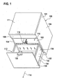
- the base cabinet 100 is replaced by a worktop 111 or, alternatively for this purpose, by a (not shown) built-in device or a (not shown) Rinse module completed.
- the lower cabinet 100 is a designated as a whole with 112 extract such taken that the drawer 112 along one of the side walls 104th the lower cabinet 100 parallel horizontal extension direction 114 from the Base cabinet extendable or in the cabinet 100 is inserted.
- the drawer 112 is attached to the drawer by means of a full drawer slide assembly 116 Base cabinet 100 held, which two aligned along the extension direction 114, perpendicular to the extension direction 114 spaced apart three-piece Pull-out guides 118 includes, which as telescopic pull-out guides are formed.
- each of the pullout guides comprises 118 a body-side guide rail 120, by means of carrier plates 122 is fixed to the bottom wall 103 of the sub-cabinet 100, a central guide rail 124, which by means of a rolling body assembly the body-side rail 120 along the extension direction 114 slidably is guided, and an exhaust-side guide rail 126 which by means of a Rolling element arrangement on the middle guide rail 124 along the extension direction 114 is guided displaceably.
- each drawer guide 118 is in each one parallel to the extension direction 114 aligned receiving groove 128 of a bottom portion 130 of a receptacle 132 formed as a receptacle 134 of the extract 112 added and in the following even closer descriptively releasably connected to the drawer 112 (see Fig. 9).
- the front in the extension direction 114 front of the drawer 112th is formed by a substantially vertical front plate 136 which is provided near its upper edge with a handle 138.
- a user By engaging the handle 138, a user can complete the drawer 112 remove from the body 101 of the cabinet 100 and into the in Figs. 1 and 2 bring shown fully extended position, in which the drawer 112 from above and from the side for loading and unloading of objects and, as will be explained below, for Adjustment of its inclination angle is freely accessible.
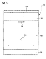
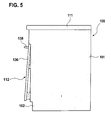
- the drawer 112 may be accessed by a user engaging the handle 138 completely inserted into the body 101 of the cabinet 100 and in the fully inserted position of the illustrated in FIGS. 3 to 5 Extract 112 are brought, in which the access opening 110 of the cabinet 100 is closed by the front plate 136.
- the drawer 112 includes a tub 132 as a receptacle 134 for receiving of items shown in Figs. 7 to 10 as a whole is.
- the trough 132 comprises the already mentioned bottom part 130, four corner supports 140, two parallel to the extension direction 114 aligned side wall portions 142, two aligned perpendicular to the extension direction 114 side wall parts 144th and a cover frame 146.
- the bottom part 130 of the trough 132 is particularly in the plan view of FIG. 10 and includes a lower bottom plate 148 and two opposite the lower bottom plate 148 upwardly offset upper floor panels 150, in their (in the extension direction 114 seen) rear portions each one essentially semicircular recess 152 is provided.
- each of Recesses 152 each have a hollow cylindrical sleeve 154 to the relevant Base plate 150 molded.
- the bottom part 130 with the sleeves 154 by an injection molding of a suitable plastic material is made.
- each sleeve 154 forms a passage opening 156, which passes through the bottom portion 130 substantially vertically and at its upper end in the interior 158 of the tub 132 and at their lower end in one of the receiving grooves 128 at the bottom of the bottom part 130 opens.
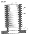
- the sleeve 154 is provided on its inside with an internal thread, which already formed in the manufacture of the bottom part 130 or with cut after the preparation of the bottom part 130 in the inside of the sleeve 154 can be.
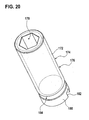
- the threaded insert 162 is on its inside with an internal thread 164th provided and has at its lower end a radially outwardly projecting Bearing flange 166, which in the mounted state of the threaded insert 162, in which the threaded insert 162 from the bottom of the Bottom part 130 ago completely screwed into the internal thread of the sleeve 154 is, flat against the lower end face of the sleeve 154.
- the adjusting screw 176 At its dipping into the threaded insert 162 upper end is the adjusting screw 176 provided with a hexagon socket 178, in which is a suitable turning tool, in particular a hexagonal key, from the interior 158 of the trough 132 can engage to the adjusting screw 176 up into the internal thread 164 of the threaded insert 162 in or down from the internal thread 164 of the threaded insert 162 to turn out.
- a suitable turning tool in particular a hexagonal key
- Adjusting screw 176 At its lower, over the threaded insert 162 projecting end is the Adjusting screw 176 provided with a screw head 180, which at its Bottom has a radial slot 182, in which a suitable Turning tool, such as a screwdriver, from the bottom of the Bottom part 130 can engage forth to the adjusting screw 176 upwards in Screw in the internal thread 164 of the threaded insert 162.
- a suitable Turning tool such as a screwdriver
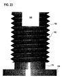
- the adjusting screw 176 is an annular groove 184 provided so that the outer diameter the adjusting screw 176 in the region of the annular groove 184 is smaller as in the adjacent areas, that is in the area of the external thread 172 and in the area of the screw head 180.
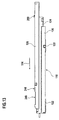
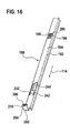
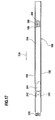
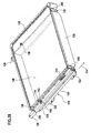
- the holding element 188 shown in detail in FIGS. 16 to 19 has substantially the shape of a profile sheet with a U-shaped cross-section, one left leg 190, one right leg 192 and one left Leg 190 with the right leg 190 connecting horizontal Bridge 194 included.
- a substantially cuboid elevation 196 in which a slot 198, in the longitudinal direction of the holding element 188 runs, extends into it.
- the slot 198 opens at the rear end of the survey 196 in a transversely to the longitudinal direction of the holding member 188 extending transverse hole 200, so that the slot 198 and the transverse hole 200 together form a substantially T-shaped Through opening in the holding element 188 form.
- the region of the elevation 196 bordering the oblong hole 198 forms the retaining edge 186 of the holding element 188, which in the annular groove 184 of the adjusting screw 176 engages and thereby the adjusting screw 176 in its axial Position fixed relative to the holding member 188, wherein (see FIGS. 30 and 31) of the Screw head 180 of the retaining edge 186 engages under and thus in the area between the holding element 188 and the drawer-side guide rail 126 is arranged is.
- the transverse hole 200 serves, the screw head 180 only in the transverse hole 200th and then from the transverse hole 200 along the slot 198 in the space below to introduce the collection 196 of the holding element 188.
- the holding member 188 With an upward from the web 194 projecting bracket 202 provided which a vertical Leg 204 and one from the top of the vertical leg 204 includes rearwardly extending shorter horizontal legs 206.
- the bracket 202 is used for locking the front end of the respective Retaining element 188 with the front of the bottom part 130th
- the bracket engages around 202 the front edge of the bottom part 130, wherein one at the top the bottom portion 130 provided nub 208 by a horizontal Leg 206 of the respective bracket 202 provided latching opening 210 (see FIGS. 16 and 17) passes through, whereby the bracket 202 after the sliding on the front edge of the bottom part 130 is no longer moved back can be.
- the remainder of the respective holding element 188 extends below the bottom part 130 through in each case one of the receiving grooves 128 therethrough.
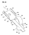
- a in Figs. 25 to 27 shown in detail locking part 212 is provided.
- the locking part 212 comprises a substantially rectangular, flat plate 214, from the lateral edges 216 each have a long latching tab 218 and in each case a short positioning tab 220 substantially vertically extend upward, (seen in the extension direction 114) on the one Side of the plate 214, the short positioning tab 220 in front of the long locking tab 218 and on the opposite side of the plate 214, the long locking tab 218 is arranged in front of the short positioning tab 220.
- a web 222 extends after behind, which connects via an angled portion 224 to the plate 214 and on its outer side is provided with a blocking element 226, which differs from the web 222 extends from substantially vertically downwards and in the Side view of a triangular contour with a substantially vertical front edge 228 and an obliquely downwardly extending rear edge 230 has.
- essentially semicircular arc 234 and one at the sheet 234 rearwardly adjoining latching tongue 236 with a substantially horizontal section 238 and extending at an angle to the horizontal sloping section 240 includes.
- the locking tabs 218 and the positioning tabs 220 of the locking part 212 serve to lock the locking part 212 to the holding element 188.
- the holding element 188 between the survey 196 and his front end two perpendicular to the longitudinal direction of the holding member 188 from each other spaced longitudinal slots 242 and one over almost the entire Width of the web 194 of the holding element 188 extending through opening 244, which is shorter on one side of the web than on the other hand.
- the latching part 212 In order to lock the latching part 212 with the holding element 188, the latching part 212 from the underside of the holding member 188 forth between its legs 190, 192 moves therethrough until the locking tabs 218 and the positioning tabs 220 pass through the longitudinal slots 242 of the holding member 188 and the locking tabs 218 after passing through their Reshape inherent elasticity so that they move back the locking part 212 to prevent down.
- a smaller, not over the entire width of the drawer-side guide rail 126 extending inlet opening 248 is behind the passage opening 246 at an outer edge of the top of the drawer-side guide rail 126 provided (see in particular Figs. 11 to 14).
- a retaining tab 250 which a from the Top of the drawer side rail 126 from upwardly extending Section 252 and one from the top of the section 252 from forwardly extending substantially horizontal portion 254.
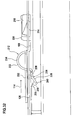
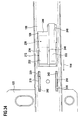
- the retaining element is pulled out Pull-out guide 118 placed on the drawer-side guide rail 126 and pushed back under a downward pressure force until the rear end of the holding element 188 passes under the retaining tab 250 and the Catching tongue 236 of the locking member 212 under elastic deformation by the Passage opening 246 at the top of the drawer-side guide rail 126 passes and in the space below the top of the drawer side Guide rail 126 is immersed, so that the latching tongue 236 from below to the bus side 126 abuts (see Figs. 32 and 33) and so on a lifting of the locking part 212 and the holding member 188 of the exhaust side Guide rail 126 upwards only possible if this is the for Deformation of the spring element 232 required force is applied.
- the blocking element occurs 226 in the inlet opening 248 at the top of the drawer-side guide rail 126, so that the locking part 212 and thus also the holding element 188 by contact of the front edge 228 of the locking element 226 with the front Edge of the inlet opening 248 against movement relative to the exhaust side Guide rail 126 along the extension direction 114 forward are secured.
- the latching of the retaining element 188 and the latching part 212 on the exhaust side Guide rail 126 is preferably in a state in which the two pullout guides 118 of the full extension guide assembly 116 both are fully extended.
- the holding member 188 through the Locking part 212 is fixed to the drain-side guide rail 126 and the Adjustment screw 176 on the one hand with the retaining edge 186 of the retaining element 188th and on the other hand is engaged with the threaded insert 162, the Pan 132 relative to the pullout guides 118 around the front lower Edge 256 of the bottom portion 130 are pivoted upwards or downwards, by adjusting screw 176 by means of one of the interior 158th the trough 132 in the hexagon recess 178 of the adjusting screw 176 inserted hexagonal key from the internal thread 164 of the threaded insert 162 out or further up into the internal thread 164 of the threaded insert 162 is rotated into it.
- the holding elements 188 are made of a metallic material, in particular made of a steel material.
- the locking parts 212 and the guide rails of the pullout guides 118th are preferably made of a metallic material, in particular of a steel material, formed.
- the front plate 136 of the drawer 112 is, as can be seen from Fig. 6, means Eccentric 258 so fixed to the front side wall portion 144a of the trough 132, that the front plate 136 relative to the trough 132 in both horizontal as well as in the vertical direction is adjustable, so that an alignment of Front plate 136 relative to the body 101 in horizontal and vertical Direction by adjusting the eccentric 258 from the interior 158 of the tub 132 can be made from.
- the relative position of the front plate 136 to the trough 132 unchanged remains, the pressure surface over which the front plate 136 at the front side wall of the trough 132 is applied, at each set inclination used to 100 percent.
- the adjusting screws 176 are from the interior 158 of the trough 132 for the implementation of the tilt adjustment very easily accessible.
- an adjusting screw 176 is in the slot 198 of the associated Holding member 188 fed to that of the retaining edge 186 of the holding element 188 comes into engagement with the annular groove 184 of the adjusting screw 176.
- the rear ends of the holding elements 188 push under the retaining tabs 250 of the extraction-side guide rails 126, and the spring elements 232 of the locking parts 212 snap into the passage openings 246 of the exhaust side Guide rails 126 a.
- This connection can be released again by lifting the front panel 136 and is moved along the extension direction 114 forward, whereby also the trough 132, on which the front plate 136 is fixed, relative to the drawer guides 118 is first moved up and then forward, whereby the latching tongues 236 of the spring elements 232 from the passage openings Move 246 of the drawer-side guide rails 126 out, so that the locking parts 212 and the holding elements 188 of the drawer-side guide rails 126 are unlocked and released.
- the relative position of the holding elements 188 remains on the exhaust side Guide rails 126 unchanged, while the bottom part 130 of the tub 132 in the region of the adjusting screws 176 relative to the holding elements 188th lowered or raised.
- the threaded insert 162 is not from the bottom the bottom part 130 is screwed into the sleeve 154, but instead the threaded insert 162 from the interior 158 of the trough 132 of is screwed into the top of the internal thread of the sleeve 154, so that the abutment flange 166 of the threaded insert 162 in the assembled state from above surface at the top of the bottom part 130 rests.
- the bottom part 130 of the drawer 112 has a receptacle for the adjusting screw 176, which is in engagement with the annular groove 184 so that the adjusting screw 176 in a rotation not in its longitudinal direction relative to the Bottom part 130 moves while the external thread 172 of the adjusting screw 176 with an arranged on the holding member 188 internal thread into engagement stands.
Landscapes
- Drawers Of Furniture (AREA)
- Vehicle Body Suspensions (AREA)
- Soil Working Implements (AREA)
- Body Structure For Vehicles (AREA)
Applications Claiming Priority (2)
| Application Number | Priority Date | Filing Date | Title |
|---|---|---|---|
| DE10345354A DE10345354A1 (de) | 2003-09-18 | 2003-09-18 | Vorrichtung zum Verstellen der Neigung eines Auszugs |
| DE10345354 | 2003-09-18 |
Publications (3)
| Publication Number | Publication Date |
|---|---|
| EP1516562A2 true EP1516562A2 (fr) | 2005-03-23 |
| EP1516562A3 EP1516562A3 (fr) | 2005-11-09 |
| EP1516562B1 EP1516562B1 (fr) | 2007-08-01 |
Family
ID=34178020
Family Applications (1)
| Application Number | Title | Priority Date | Filing Date |
|---|---|---|---|
| EP04022122A Expired - Lifetime EP1516562B1 (fr) | 2003-09-18 | 2004-09-17 | Dispositif pour regler l'inclinaison d'un tiroir |
Country Status (4)
| Country | Link |
|---|---|
| EP (1) | EP1516562B1 (fr) |
| AT (1) | ATE368402T1 (fr) |
| DE (2) | DE10345354A1 (fr) |
| DK (1) | DK1516562T3 (fr) |
Cited By (6)
| Publication number | Priority date | Publication date | Assignee | Title |
|---|---|---|---|---|
| EP2468135A1 (fr) * | 2010-12-23 | 2012-06-27 | Grass GmbH | Meuble doté d'un dispositif destiné à l'application d'une unité de guidage |
| AT509413B1 (de) * | 2010-02-03 | 2012-12-15 | Blum Gmbh Julius | Neigungsvorrichtung für schubladen |
| AT512414A5 (de) * | 2009-03-06 | 2013-08-15 | Hettich Paul Gmbh & Co Kg | Seitenzargenanordnung mit möbelauszugsführung |
| CN103622328A (zh) * | 2013-12-18 | 2014-03-12 | 伍志勇 | 抽屉的位置调节机构 |
| US9039108B2 (en) | 2011-04-19 | 2015-05-26 | Julius Blum Gmbh | Drawer frame having a tilt adjustment |
| WO2019001954A1 (fr) * | 2017-06-28 | 2019-01-03 | Paul Hettich Gmbh & Co. Kg | Système d'extraction et procédé d'ouverture et de fermeture d'un élément tiroir |
Family Cites Families (5)
| Publication number | Priority date | Publication date | Assignee | Title |
|---|---|---|---|---|
| DE8228143U1 (de) * | 1982-10-07 | 1983-01-13 | Hagenhenrich Gmbh & Co Kg Metallwarenfabrik, 4837 Verl | Unterflur-auszugsfuehrung |
| DE9215250U1 (de) * | 1992-11-10 | 1993-02-25 | Grass AG, Höchst, Vorarlberg | Schubladenführung mit lösbarer Schubladenschiene |
| ES2162579B1 (es) * | 1999-09-16 | 2002-08-01 | Calvo Miguel Angel Rioja | Dispositivo de regulacion vertical para cajones de muebles. |
| AT409067B (de) * | 2000-03-02 | 2002-05-27 | Blum Gmbh Julius | Ausziehführung für schubladen |
| TWI249389B (en) * | 2002-06-19 | 2006-02-21 | Salice Arturo Spa | Device for adjusting the height of a drawer |
-
2003
- 2003-09-18 DE DE10345354A patent/DE10345354A1/de not_active Withdrawn
-
2004
- 2004-09-17 DK DK04022122T patent/DK1516562T3/da active
- 2004-09-17 EP EP04022122A patent/EP1516562B1/fr not_active Expired - Lifetime
- 2004-09-17 AT AT04022122T patent/ATE368402T1/de not_active IP Right Cessation
- 2004-09-17 DE DE502004004495T patent/DE502004004495D1/de not_active Expired - Lifetime
Cited By (7)
| Publication number | Priority date | Publication date | Assignee | Title |
|---|---|---|---|---|
| AT512414A5 (de) * | 2009-03-06 | 2013-08-15 | Hettich Paul Gmbh & Co Kg | Seitenzargenanordnung mit möbelauszugsführung |
| AT512414B1 (de) * | 2009-03-06 | 2013-08-15 | Hettich Paul Gmbh & Co Kg | Seitenzargenanordnung mit möbelauszugsführung |
| AT509413B1 (de) * | 2010-02-03 | 2012-12-15 | Blum Gmbh Julius | Neigungsvorrichtung für schubladen |
| EP2468135A1 (fr) * | 2010-12-23 | 2012-06-27 | Grass GmbH | Meuble doté d'un dispositif destiné à l'application d'une unité de guidage |
| US9039108B2 (en) | 2011-04-19 | 2015-05-26 | Julius Blum Gmbh | Drawer frame having a tilt adjustment |
| CN103622328A (zh) * | 2013-12-18 | 2014-03-12 | 伍志勇 | 抽屉的位置调节机构 |
| WO2019001954A1 (fr) * | 2017-06-28 | 2019-01-03 | Paul Hettich Gmbh & Co. Kg | Système d'extraction et procédé d'ouverture et de fermeture d'un élément tiroir |
Also Published As
| Publication number | Publication date |
|---|---|
| DK1516562T3 (da) | 2007-10-01 |
| ATE368402T1 (de) | 2007-08-15 |
| DE502004004495D1 (de) | 2007-09-13 |
| EP1516562B1 (fr) | 2007-08-01 |
| DE10345354A1 (de) | 2005-04-28 |
| EP1516562A3 (fr) | 2005-11-09 |
Similar Documents
| Publication | Publication Date | Title |
|---|---|---|
| EP2699123B1 (fr) | Paroi latérale d'inclinaison réglable pour tiroir | |
| EP1690472B1 (fr) | Guide de tiroir | |
| DE69917202T2 (de) | Schreibtisch | |
| EP2440088B1 (fr) | Guide télescopique pour tiroirs | |
| DE2412114A1 (de) | Vorrichtung zum verriegeln bestimmter von mehreren herausziehbaren aufbewahrungseinheiten bei einer aufbewahrungseinrichtung, z.b. einem schrank | |
| DE202007001780U1 (de) | Schubkasten | |
| DE102014104136A1 (de) | Auszugsführung für einen Schubkasten und Verfahren zur Befestigung eines Schubkastens an einer Auszugsführung | |
| DE102009025890A1 (de) | Vorrichtung zur Befestigung einer Frontblende an einer Seitenzarge eines beweglichen Möbelteils eines Möbels, Schubkasten und Möbel | |
| DE112014006148B4 (de) | Anordnung mit einer Schubladenausziehführung und mit einer Frontblende aufweisenden Schublade | |
| EP3727090A1 (fr) | Paroi latérale de tiroir pourvu de profilé de couverture | |
| EP0674863B1 (fr) | Dispositif de guidage pour tiroirs | |
| EP2801291A1 (fr) | Ferrure de meuble pour former un dispositif coulissant de collecte de déchets | |
| EP1516562B1 (fr) | Dispositif pour regler l'inclinaison d'un tiroir | |
| AT515689B1 (de) | Schublade | |
| EP3783287A1 (fr) | Étagère pourvue d'un support central spécifique pour des parties de plaque séparées | |
| EP3783288B1 (fr) | Clayette pourvue de cadre de support à trois côtés | |
| EP4424960A1 (fr) | Dispositif de charnière, charnière de butée et unité fonctionnelle | |
| DE102017110499A1 (de) | Hubmechanismus mit einer Ablage, Möbel und Schubkasten | |
| EP3569121B1 (fr) | Ensemble lavabo | |
| DE69002342T2 (de) | Befestigungsvorrichtung durch Zusammenschrauben auf einem Profil, insbesondere auf einem Elektrizitätsschrank. | |
| WO2013029780A2 (fr) | Unité meuble | |
| EP2774508B1 (fr) | Sortie latérale avec guides de tiroir coulissant et pièces de maintien | |
| DE10331867B4 (de) | Vorrichtung zum Führen und Halten wenigstens eines ausziehbaren, plattenförmigen Elementes | |
| DE1240250B (de) | Tragvorrichtung fuer Ausziehplatten, Schubladen od. dgl. von Moebeln | |
| DE102024003729A1 (de) | Schienensystem zur Auszugführung |
Legal Events
| Date | Code | Title | Description |
|---|---|---|---|
| PUAI | Public reference made under article 153(3) epc to a published international application that has entered the european phase |
Free format text: ORIGINAL CODE: 0009012 |
|
| AK | Designated contracting states |
Kind code of ref document: A2 Designated state(s): AT BE BG CH CY CZ DE DK EE ES FI FR GB GR HU IE IT LI LU MC NL PL PT RO SE SI SK TR |
|
| AX | Request for extension of the european patent |
Extension state: AL HR LT LV MK |
|
| PUAL | Search report despatched |
Free format text: ORIGINAL CODE: 0009013 |
|
| AK | Designated contracting states |
Kind code of ref document: A3 Designated state(s): AT BE BG CH CY CZ DE DK EE ES FI FR GB GR HU IE IT LI LU MC NL PL PT RO SE SI SK TR |
|
| AX | Request for extension of the european patent |
Extension state: AL HR LT LV MK |
|
| 17P | Request for examination filed |
Effective date: 20060330 |
|
| AKX | Designation fees paid |
Designated state(s): AT BE BG CH CY CZ DE DK EE ES FI FR GB GR HU IE IT LI LU MC NL PL PT RO SE SI SK TR |
|
| GRAP | Despatch of communication of intention to grant a patent |
Free format text: ORIGINAL CODE: EPIDOSNIGR1 |
|
| GRAS | Grant fee paid |
Free format text: ORIGINAL CODE: EPIDOSNIGR3 |
|
| GRAA | (expected) grant |
Free format text: ORIGINAL CODE: 0009210 |
|
| AK | Designated contracting states |
Kind code of ref document: B1 Designated state(s): AT BE BG CH CY CZ DE DK EE ES FI FR GB GR HU IE IT LI LU MC NL PL PT RO SE SI SK TR |
|
| REG | Reference to a national code |
Ref country code: GB Ref legal event code: FG4D Free format text: NOT ENGLISH |
|
| REG | Reference to a national code |
Ref country code: CH Ref legal event code: EP |
|
| REG | Reference to a national code |
Ref country code: IE Ref legal event code: FG4D Free format text: LANGUAGE OF EP DOCUMENT: GERMAN |
|
| REF | Corresponds to: |
Ref document number: 502004004495 Country of ref document: DE Date of ref document: 20070913 Kind code of ref document: P |
|
| REG | Reference to a national code |
Ref country code: CH Ref legal event code: PCAR Free format text: ISLER & PEDRAZZINI AG;POSTFACH 1772;8027 ZUERICH (CH) Ref country code: CH Ref legal event code: NV Representative=s name: ISLER & PEDRAZZINI AG |
|
| REG | Reference to a national code |
Ref country code: DK Ref legal event code: T3 |
|
| REG | Reference to a national code |
Ref country code: SE Ref legal event code: TRGR |
|
| ET | Fr: translation filed | ||
| PG25 | Lapsed in a contracting state [announced via postgrant information from national office to epo] |
Ref country code: NL Free format text: LAPSE BECAUSE OF FAILURE TO SUBMIT A TRANSLATION OF THE DESCRIPTION OR TO PAY THE FEE WITHIN THE PRESCRIBED TIME-LIMIT Effective date: 20070801 Ref country code: BG Free format text: LAPSE BECAUSE OF FAILURE TO SUBMIT A TRANSLATION OF THE DESCRIPTION OR TO PAY THE FEE WITHIN THE PRESCRIBED TIME-LIMIT Effective date: 20071101 Ref country code: ES Free format text: LAPSE BECAUSE OF FAILURE TO SUBMIT A TRANSLATION OF THE DESCRIPTION OR TO PAY THE FEE WITHIN THE PRESCRIBED TIME-LIMIT Effective date: 20071112 Ref country code: FI Free format text: LAPSE BECAUSE OF FAILURE TO SUBMIT A TRANSLATION OF THE DESCRIPTION OR TO PAY THE FEE WITHIN THE PRESCRIBED TIME-LIMIT Effective date: 20070801 |
|
| NLV1 | Nl: lapsed or annulled due to failure to fulfill the requirements of art. 29p and 29m of the patents act | ||
| GBV | Gb: ep patent (uk) treated as always having been void in accordance with gb section 77(7)/1977 [no translation filed] |
Effective date: 20070801 |
|
| PG25 | Lapsed in a contracting state [announced via postgrant information from national office to epo] |
Ref country code: PL Free format text: LAPSE BECAUSE OF FAILURE TO SUBMIT A TRANSLATION OF THE DESCRIPTION OR TO PAY THE FEE WITHIN THE PRESCRIBED TIME-LIMIT Effective date: 20070801 |
|
| REG | Reference to a national code |
Ref country code: IE Ref legal event code: FD4D |
|
| BERE | Be: lapsed |
Owner name: BLANCO G.M.B.H. + CO KG Effective date: 20070930 |
|
| PG25 | Lapsed in a contracting state [announced via postgrant information from national office to epo] |
Ref country code: GR Free format text: LAPSE BECAUSE OF FAILURE TO SUBMIT A TRANSLATION OF THE DESCRIPTION OR TO PAY THE FEE WITHIN THE PRESCRIBED TIME-LIMIT Effective date: 20071102 Ref country code: MC Free format text: LAPSE BECAUSE OF NON-PAYMENT OF DUE FEES Effective date: 20070930 |
|
| PG25 | Lapsed in a contracting state [announced via postgrant information from national office to epo] |
Ref country code: GB Free format text: LAPSE BECAUSE OF FAILURE TO SUBMIT A TRANSLATION OF THE DESCRIPTION OR TO PAY THE FEE WITHIN THE PRESCRIBED TIME-LIMIT Effective date: 20070801 Ref country code: CZ Free format text: LAPSE BECAUSE OF FAILURE TO SUBMIT A TRANSLATION OF THE DESCRIPTION OR TO PAY THE FEE WITHIN THE PRESCRIBED TIME-LIMIT Effective date: 20070801 Ref country code: SK Free format text: LAPSE BECAUSE OF FAILURE TO SUBMIT A TRANSLATION OF THE DESCRIPTION OR TO PAY THE FEE WITHIN THE PRESCRIBED TIME-LIMIT Effective date: 20070801 Ref country code: IE Free format text: LAPSE BECAUSE OF FAILURE TO SUBMIT A TRANSLATION OF THE DESCRIPTION OR TO PAY THE FEE WITHIN THE PRESCRIBED TIME-LIMIT Effective date: 20070801 Ref country code: PT Free format text: LAPSE BECAUSE OF FAILURE TO SUBMIT A TRANSLATION OF THE DESCRIPTION OR TO PAY THE FEE WITHIN THE PRESCRIBED TIME-LIMIT Effective date: 20080102 |
|
| PLBE | No opposition filed within time limit |
Free format text: ORIGINAL CODE: 0009261 |
|
| STAA | Information on the status of an ep patent application or granted ep patent |
Free format text: STATUS: NO OPPOSITION FILED WITHIN TIME LIMIT |
|
| PG25 | Lapsed in a contracting state [announced via postgrant information from national office to epo] |
Ref country code: RO Free format text: LAPSE BECAUSE OF FAILURE TO SUBMIT A TRANSLATION OF THE DESCRIPTION OR TO PAY THE FEE WITHIN THE PRESCRIBED TIME-LIMIT Effective date: 20070801 |
|
| 26N | No opposition filed |
Effective date: 20080506 |
|
| PG25 | Lapsed in a contracting state [announced via postgrant information from national office to epo] |
Ref country code: BE Free format text: LAPSE BECAUSE OF NON-PAYMENT OF DUE FEES Effective date: 20070930 |
|
| PG25 | Lapsed in a contracting state [announced via postgrant information from national office to epo] |
Ref country code: AT Free format text: LAPSE BECAUSE OF NON-PAYMENT OF DUE FEES Effective date: 20070917 |
|
| PG25 | Lapsed in a contracting state [announced via postgrant information from national office to epo] |
Ref country code: EE Free format text: LAPSE BECAUSE OF FAILURE TO SUBMIT A TRANSLATION OF THE DESCRIPTION OR TO PAY THE FEE WITHIN THE PRESCRIBED TIME-LIMIT Effective date: 20070801 |
|
| PG25 | Lapsed in a contracting state [announced via postgrant information from national office to epo] |
Ref country code: SI Free format text: LAPSE BECAUSE OF FAILURE TO SUBMIT A TRANSLATION OF THE DESCRIPTION OR TO PAY THE FEE WITHIN THE PRESCRIBED TIME-LIMIT Effective date: 20070801 |
|
| PG25 | Lapsed in a contracting state [announced via postgrant information from national office to epo] |
Ref country code: CY Free format text: LAPSE BECAUSE OF FAILURE TO SUBMIT A TRANSLATION OF THE DESCRIPTION OR TO PAY THE FEE WITHIN THE PRESCRIBED TIME-LIMIT Effective date: 20070801 |
|
| PG25 | Lapsed in a contracting state [announced via postgrant information from national office to epo] |
Ref country code: LU Free format text: LAPSE BECAUSE OF NON-PAYMENT OF DUE FEES Effective date: 20070917 |
|
| PG25 | Lapsed in a contracting state [announced via postgrant information from national office to epo] |
Ref country code: TR Free format text: LAPSE BECAUSE OF FAILURE TO SUBMIT A TRANSLATION OF THE DESCRIPTION OR TO PAY THE FEE WITHIN THE PRESCRIBED TIME-LIMIT Effective date: 20070801 Ref country code: HU Free format text: LAPSE BECAUSE OF FAILURE TO SUBMIT A TRANSLATION OF THE DESCRIPTION OR TO PAY THE FEE WITHIN THE PRESCRIBED TIME-LIMIT Effective date: 20080202 |
|
| PG25 | Lapsed in a contracting state [announced via postgrant information from national office to epo] |
Ref country code: IT Free format text: LAPSE BECAUSE OF NON-PAYMENT OF DUE FEES Effective date: 20070930 |
|
| PGFP | Annual fee paid to national office [announced via postgrant information from national office to epo] |
Ref country code: DK Payment date: 20110912 Year of fee payment: 8 Ref country code: CH Payment date: 20110913 Year of fee payment: 8 |
|
| PGFP | Annual fee paid to national office [announced via postgrant information from national office to epo] |
Ref country code: SE Payment date: 20120911 Year of fee payment: 9 |
|
| REG | Reference to a national code |
Ref country code: SE Ref legal event code: EUG |
|
| PG25 | Lapsed in a contracting state [announced via postgrant information from national office to epo] |
Ref country code: SE Free format text: LAPSE BECAUSE OF NON-PAYMENT OF DUE FEES Effective date: 20130918 |
|
| REG | Reference to a national code |
Ref country code: CH Ref legal event code: PL |
|
| REG | Reference to a national code |
Ref country code: DK Ref legal event code: EBP Effective date: 20130930 |
|
| PG25 | Lapsed in a contracting state [announced via postgrant information from national office to epo] |
Ref country code: LI Free format text: LAPSE BECAUSE OF NON-PAYMENT OF DUE FEES Effective date: 20130930 Ref country code: CH Free format text: LAPSE BECAUSE OF NON-PAYMENT OF DUE FEES Effective date: 20130930 |
|
| REG | Reference to a national code |
Ref country code: DE Ref legal event code: R082 Ref document number: 502004004495 Representative=s name: OTTEN, ROTH, DOBLER & PARTNER PATENTANWAELTE, DE Country of ref document: DE |
|
| PG25 | Lapsed in a contracting state [announced via postgrant information from national office to epo] |
Ref country code: DK Free format text: LAPSE BECAUSE OF NON-PAYMENT OF DUE FEES Effective date: 20130930 |
|
| PGFP | Annual fee paid to national office [announced via postgrant information from national office to epo] |
Ref country code: FR Payment date: 20140919 Year of fee payment: 11 |
|
| REG | Reference to a national code |
Ref country code: DE Ref legal event code: R081 Ref document number: 502004004495 Country of ref document: DE Owner name: GRASS GMBH, AT Free format text: FORMER OWNER: BLANCO GMBH + CO KG, 75038 OBERDERDINGEN, DE Effective date: 20141127 Ref country code: DE Ref legal event code: R082 Ref document number: 502004004495 Country of ref document: DE Representative=s name: OTTEN, ROTH, DOBLER & PARTNER PATENTANWAELTE, DE Effective date: 20140825 Ref country code: DE Ref legal event code: R082 Ref document number: 502004004495 Country of ref document: DE Representative=s name: OTTEN, ROTH, DOBLER & PARTNER MBB PATENTANWAEL, DE Effective date: 20140825 |
|
| REG | Reference to a national code |
Ref country code: FR Ref legal event code: TP Owner name: GRASS GMBH MOBELBESCHLAGE, AT Effective date: 20141223 |
|
| REG | Reference to a national code |
Ref country code: FR Ref legal event code: ST Effective date: 20160531 |
|
| PG25 | Lapsed in a contracting state [announced via postgrant information from national office to epo] |
Ref country code: FR Free format text: LAPSE BECAUSE OF NON-PAYMENT OF DUE FEES Effective date: 20150930 |
|
| REG | Reference to a national code |
Ref country code: DE Ref legal event code: R079 Ref document number: 502004004495 Country of ref document: DE Free format text: PREVIOUS MAIN CLASS: A47B0088040000 Ipc: A47B0088400000 |
|
| PGFP | Annual fee paid to national office [announced via postgrant information from national office to epo] |
Ref country code: DE Payment date: 20190724 Year of fee payment: 16 |
|
| REG | Reference to a national code |
Ref country code: DE Ref legal event code: R119 Ref document number: 502004004495 Country of ref document: DE |
|
| PG25 | Lapsed in a contracting state [announced via postgrant information from national office to epo] |
Ref country code: DE Free format text: LAPSE BECAUSE OF NON-PAYMENT OF DUE FEES Effective date: 20210401 |