EP4424960A1 - Dispositif de charnière, charnière de butée et unité fonctionnelle - Google Patents
Dispositif de charnière, charnière de butée et unité fonctionnelle Download PDFInfo
- Publication number
- EP4424960A1 EP4424960A1 EP23160072.7A EP23160072A EP4424960A1 EP 4424960 A1 EP4424960 A1 EP 4424960A1 EP 23160072 A EP23160072 A EP 23160072A EP 4424960 A1 EP4424960 A1 EP 4424960A1
- Authority
- EP
- European Patent Office
- Prior art keywords
- stop
- hinge
- lever
- mounting
- door
- Prior art date
- Legal status (The legal status is an assumption and is not a legal conclusion. Google has not performed a legal analysis and makes no representation as to the accuracy of the status listed.)
- Pending
Links
- 230000008878 coupling Effects 0.000 claims description 41
- 238000010168 coupling process Methods 0.000 claims description 41
- 238000005859 coupling reaction Methods 0.000 claims description 41
- 238000013016 damping Methods 0.000 claims description 27
- 238000006073 displacement reaction Methods 0.000 claims description 21
- 230000005540 biological transmission Effects 0.000 claims description 6
- 230000007246 mechanism Effects 0.000 claims description 4
- 238000009434 installation Methods 0.000 description 4
- 230000000712 assembly Effects 0.000 description 3
- 238000000429 assembly Methods 0.000 description 3
- 230000008901 benefit Effects 0.000 description 3
- 239000002184 metal Substances 0.000 description 2
- 238000005192 partition Methods 0.000 description 2
- 229920006324 polyoxymethylene Polymers 0.000 description 2
- 229930040373 Paraformaldehyde Natural products 0.000 description 1
- 238000010276 construction Methods 0.000 description 1
- 239000003112 inhibitor Substances 0.000 description 1
- 238000000034 method Methods 0.000 description 1
- 238000009740 moulding (composite fabrication) Methods 0.000 description 1
- -1 polyoxymethylene Polymers 0.000 description 1
- 230000008569 process Effects 0.000 description 1
Images


Classifications
-
- E—FIXED CONSTRUCTIONS
- E05—LOCKS; KEYS; WINDOW OR DOOR FITTINGS; SAFES
- E05D—HINGES OR SUSPENSION DEVICES FOR DOORS, WINDOWS OR WINGS
- E05D15/00—Suspension arrangements for wings
- E05D15/56—Suspension arrangements for wings with successive different movements
- E05D15/58—Suspension arrangements for wings with successive different movements with both swinging and sliding movements
-
- E—FIXED CONSTRUCTIONS
- E05—LOCKS; KEYS; WINDOW OR DOOR FITTINGS; SAFES
- E05D—HINGES OR SUSPENSION DEVICES FOR DOORS, WINDOWS OR WINGS
- E05D5/00—Construction of single parts, e.g. the parts for attachment
- E05D5/02—Parts for attachment, e.g. flaps
- E05D5/0215—Parts for attachment, e.g. flaps for attachment to profile members or the like
- E05D5/0223—Parts for attachment, e.g. flaps for attachment to profile members or the like with parts, e.g. screws, extending through the profile wall or engaging profile grooves
- E05D5/0238—Parts for attachment, e.g. flaps for attachment to profile members or the like with parts, e.g. screws, extending through the profile wall or engaging profile grooves with parts engaging profile grooves
-
- E—FIXED CONSTRUCTIONS
- E05—LOCKS; KEYS; WINDOW OR DOOR FITTINGS; SAFES
- E05D—HINGES OR SUSPENSION DEVICES FOR DOORS, WINDOWS OR WINGS
- E05D15/00—Suspension arrangements for wings
- E05D15/26—Suspension arrangements for wings for folding wings
-
- E—FIXED CONSTRUCTIONS
- E05—LOCKS; KEYS; WINDOW OR DOOR FITTINGS; SAFES
- E05D—HINGES OR SUSPENSION DEVICES FOR DOORS, WINDOWS OR WINGS
- E05D15/00—Suspension arrangements for wings
- E05D15/56—Suspension arrangements for wings with successive different movements
- E05D15/58—Suspension arrangements for wings with successive different movements with both swinging and sliding movements
- E05D2015/586—Suspension arrangements for wings with successive different movements with both swinging and sliding movements with travelling hinge parts
-
- E—FIXED CONSTRUCTIONS
- E05—LOCKS; KEYS; WINDOW OR DOOR FITTINGS; SAFES
- E05Y—INDEXING SCHEME ASSOCIATED WITH SUBCLASSES E05D AND E05F, RELATING TO CONSTRUCTION ELEMENTS, ELECTRIC CONTROL, POWER SUPPLY, POWER SIGNAL OR TRANSMISSION, USER INTERFACES, MOUNTING OR COUPLING, DETAILS, ACCESSORIES, AUXILIARY OPERATIONS NOT OTHERWISE PROVIDED FOR, APPLICATION THEREOF
- E05Y2900/00—Application of doors, windows, wings or fittings thereof
- E05Y2900/20—Application of doors, windows, wings or fittings thereof for furniture, e.g. cabinets
- E05Y2900/212—Doors disappearing in pockets in the furniture body
Definitions
- the invention relates to a hinge device for rotatably holding and moving a door which has at least one door element, a stop hinge for this hinge device and a functional unit, in particular a piece of furniture, with at least one such hinge device.
- hinge devices that comprise a slidably held stop profile and stop hinges that rotatably connect the stop profile to the door.
- the US9284761B2 discloses a piece of furniture with a sliding device by means of which a stop profile connected to a folding sliding door can be moved within a door compartment.
- the folding sliding door comprises two door elements connected to one another by door hinges, of which the first door element is connected to a stop profile at the rear by stop hinges and the second is connected to a guide carriage at the front.
- the stop profile is held displaceably in a vertical orientation by a sliding device and is provided with support carriages on the top and bottom that are guided in a support rail.
- the guide carriage can be moved along a guide rail that has three rail sections, of which a first and a second rail section are connected to one another by a third rail section running along a curve. The first rail section runs into the door compartment and the second rail section runs along the front of the piece of furniture.
- the folding door is extended from the door compartment and unfolded. In the closed position, the door elements are aligned flat to one another. To open the piece of furniture, the folding door is folded back into place, with the door elements in an open position preferably aligned parallel to one another and retracted into the door compartment.
- the hinge device which connects the stop profile and the Includes stop hinges, adjustable so that the door can be moved vertically and horizontally.
- the US8336972B2 discloses a hinge device with a stop profile that is provided with adjustable stop hinges. By adjusting the stop hinges, the held door element can be moved horizontally. The vertical adjustment of the door element is carried out by vertical displacement of the stop profile, which is held by an adjustable drive.
- Another disadvantage is that other device parts that are connected to the stop profile and that fulfill other functions are moved together with the stop profile and may also have to be readjusted.
- the US8336972B2 also discloses a stop hinge which has a lever mechanism with a mounting lever which is provided with a rack along which a mounting part connected to the door element can be moved by engaging the rack with a screwdriver, which is why signs of wear can occur.
- the present invention is therefore based on the object of creating an improved hinge device for a functional unit, an improved hinge for this hinge device and an improved functional unit with such a hinge device.
- the hinge device according to the invention which has a displaceably mounted stop profile and at least two stop hinges connected thereto, should be of simple construction, advantageous to install and easy, convenient and quick to adjust in order to precisely align a door element held by the hinge device, possibly a folding door or folding sliding door, with respect to an opening of a functional unit to be closed.
- the door or a door element should particularly advantageously be connectable to the hinge device and detachable from it so that installation work or subsequent interventions in the functional unit are easily possible.
- Drives used to move the stop profile into a door compartment should be designed simply and have reduced dimensions so that the door compartment can be realized with smaller dimensions or so that more space is available for other device parts.
- a stop hinge should be created for this hinge device, which is robustly constructed and advantageously adjustable. Signs of wear should be avoided with this stop hinge, even after multiple adjustments.
- the hinge device should allow the held door element to rotate automatically into the end position.
- the movement of the door element should preferably be dampened so that annoying slamming of the door element is avoided.
- two adjustable stop hinges should be able to be mounted next to each other or one above the other on the stop profile, which can be adjusted without the adjustment of one stop hinge being hindered by the second stop hinge.
- the hinge device which is provided for a functional unit which has a door with at least one door element, by means of which a door opening can be completely or partially closed and which can be moved into a door compartment after the door opening has been opened, comprises a stop profile as well as a stop hinge and at least one auxiliary hinge, which on the one hand are detachably connected to the stop profile and on the other hand can be connected to the door element.
- the stop profile has an anchor channel
- a support device is provided with a support body which comprises a support anchor which is displaceable in the anchor channel and with at least one locking screw
- the support device comprises a slider which is slidably mounted in the support body and an adjusting element which is provided for displacing and holding the slider
- a holding device is provided with a holding body which comprises a holding anchor which is slidably held in the anchor channel and a holding element
- the stop hinge has a stop body which is supported directly or indirectly on the slider and which is held by the holding element of the holding device after the latter has been displaced against the stop hinge.
- the auxiliary hinge is preferably identical to the stop hinge, which is why the following statements on the stop hinge also describe the auxiliary hinge in the preferred embodiment.
- the support anchor of the support device and the holding anchor of the holding device preferably have at least approximately the same cross-section, so that both are held in the anchor channel so that they can be moved but are largely free of play.
- the holding anchor of the holding device which is preferably made of plastic, preferably has locking elements that prevent the holding device from moving automatically. The holding device can therefore be raised to a point where it is held automatically and can then be moved manually against the stop hinge.
- the auxiliary hinge is also associated with a holding device which can be moved upwards before the door is mounted and can then also be moved manually against the auxiliary hinge.
- the support device is first moved to a specified height and fixed.
- the door element with the stop hinge is then placed on the support device.
- the holding devices are then moved against the stop hinge and the auxiliary hinge to secure them so that they can no longer come loose from the stop profile.
- the support device is then adjusted to raise or lower the supported door to the required height.
- stop hinge and the auxiliary hinge or hinges fixed, preferably using connecting screws.
- the stop screws provided on the stop body of the stop hinge and the auxiliary hinge are screwed into threaded parts that are provided as one piece in the holding body of the holding device or are integrated into it, if necessary cast in.
- the door element can therefore be installed conveniently in just a few steps. It is particularly helpful that the door element can be temporarily connected to the stop profile in a first step and secured by moving the holding devices.
- the adjustment priority can then be easily carried out by operating the adjustable support device and preferably lifting the door element slightly to make it easier to adjust the support device.
- the support device is preferably self-locking under the load of the door element. The stop screws can then be tightened easily.
- the stop profile is rod-shaped and preferably has the same profile cross-section over its entire length, which can have additional profile elements in addition to the anchor channel that are suitable for connection to other device parts.
- an assembly channel is provided into which a connecting part of an upper drive or a lower drive, for example a part of the drive body, can be inserted.
- the distance between the stop profile and the upper drive and/or the lower drive can be adjusted in stages so that pre-setting is possible. Any remaining deviation from the desired height of the raised door element can then be corrected by actuating the support device.
- the upper drive and the lower drive are preferably each guided in a retaining rail that runs into the door compartment of the functional unit.
- a coupling carriage is provided with a carriage body which comprises a carriage anchor which is slidably held in the anchor channel.
- the cross section of the carriage anchor preferably corresponds to the cross section of the support anchor, so that the The coupling carriage can also be moved within the anchor channel with virtually no play.
- the coupling carriage which is arranged between the slide and the stop body of the stop hinge, is supported on the underside by the slide and is provided on the top with at least one coupling element that can engage positively in the stop body of the stop hinge.
- a bearing channel is provided in the slide body, along which the coupling element supported by a support spring can be moved and completely or partially sunk into the slide body.
- a slide channel and an actuating chamber are preferably provided in the support body.
- the slide is mounted in the slide channel so that it can be moved axially.
- the actuating element is rotatably held in the actuating chamber and is connected in a force-fitting manner or as one piece to an eccentrically arranged eccentric part or an eccentrically running eccentric part.
- the eccentric part is in contact with the slide or a part of it and can move the slide axially outwards when the actuating element is actuated.
- the slide is returned to the slide channel.
- the slider has track segments which delimit the at least one guide track into which the eccentric part can engage, which is preferably designed as a spiral which runs eccentrically outwards.
- the stop body of the stop hinge is connected by a lever mechanism comprising a drive lever, an adjusting lever and an assembly lever to an assembly part, for example a hinge cup, which can be connected to the associated door element.
- the mounting part can be moved and locked along a displacement axis and has a mounting plate in which a longitudinal opening running parallel to the displacement axis and a guide channel running perpendicular or inclined to the displacement axis are provided.
- the displacement axis is aligned perpendicular to the stop profile, which is why the raised door element can be moved sideways and also aligned vertically
- the drive lever which is connected to a drive spring in a force-locking manner, is connected to the stop body on the one hand by a first lever shaft and to a first end piece of the assembly lever on the other hand by a fourth lever shaft.
- the adjusting lever is connected to the stop body on the one hand by a second lever shaft and to a second end piece of the assembly lever on the other hand by a third lever shaft.
- the mounting lever is integrally connected, in a force-fitting and/or form-fitting manner, to a mounting body in which an eccentric chamber and a screw chamber are provided.
- a cylindrical eccentric body is mounted so that it can rotate about a rotation axis, which holds an eccentric part that is spaced from the rotation axis and engages in the guide channel.
- the eccentric part is, for example, a pin or rod, a rotatably mounted sleeve or a roller.
- a fixing screw is held in the screw chamber, which penetrates the longitudinal opening in the mounting plate and is connected to a lock nut.
- the mounting part or the hinge cup can therefore be moved by rotating the eccentric body. During this movement, the position of the fixing screw changes within the longitudinal opening of the mounting plate. The movement of the mounting part is therefore not hindered by the fixing screw. Only after the desired movement of the mounting part has taken place is the fixing screw connected to the lock nut tightened.
- the longitudinal opening of the mounting plate is preferably connected to a guideway in which the lock nut is held in a rotationally fixed manner.
- the lock nut is, for example, polygonal, or square, and is recessed into the guideway, which allows the lock nut to be moved but not rotated.
- the mounting part and the mounting body In order to ensure that the mounting part and the mounting body can be moved against each other precisely and without rotation, they preferably have guide elements that lie against each other and run parallel to the displacement axis.
- the mounting plate is provided with a guide rib that can engage in a guide groove in the mounting body.
- the guide channel into which the eccentric part engages is preferably part of an engagement opening which has a receiving opening adjoining the guide channel, the dimensions of which correspond to the dimensions of the eccentric body.
- the mounting part can therefore be placed on the mounting body regardless of the position of the eccentric body. The eccentric part can easily engage in the receiving opening.
- the receiving opening has at least one guide edge which runs towards the guide channel and along which the eccentric part guided into the receiving opening is practically automatically guided into the guide channel when the mounting part is displaced relative to the mounting body.
- a closure part is provided which can be inserted into the engagement opening after the connection of the mounting part to the mounting body in order to enclose the eccentric part within the guide channel.
- the stop body has a damping chamber in which a damping element is arranged, which comprises a damping cylinder and a damping piston with a piston rod guided therein.
- a damping element is an oil damper or a pneumatic damper, which prevents the stop hinge from making jerky movements.
- the damping element To actuate the damping element, it is provided with a transmission part that interacts with an actuating arm that is preferably provided on the drive lever, which is driven by a drive spring.
- the drive spring has, for example, two spring assemblies connected to one another by a spring center piece, through which the first lever shaft is guided.
- the end pieces of the spring assemblies are preferably anchored to the stop body of the stop hinge, while the spring center piece acts on the drive lever.
- the functional unit has at least one single-part or multi-part door, such as a folding door, each of which is held by a hinge device according to the invention and can preferably be inserted into a door compartment.
- Fig.1 shows a functional unit 1 according to the invention in the design of a piece of furniture with a first hinge device 2, which has a stop profile 21 and a stop hinge 3 and an auxiliary hinge 3 ' mounted thereon, and with a second hinge device 2', which has a stop profile 21 and a stop hinge 3 and an auxiliary hinge 3 ' mounted thereon, and with a folding sliding door 11, which is held by the first hinge device 2 so that it can rotate and can be moved into an associated door compartment 10, and with a single door 11 ' , which is held by the second hinge device 2 ' so that it can rotate and can be moved into an associated door compartment 10.
- the piece of furniture 1 has side walls 1A, an upper floor 1B, a lower floor 1C, an intermediate floor 1E and partition walls 1D, each of which delimits a door compartment 10 with one of the side walls 1A.
- the folding door 11 has a first door element 111, which is connected on one side by stop hinges 3 to a stop profile 21, and on the other side by door hinges 14 to a second door element 112, the dimensions of which preferably correspond to the dimensions of the first door element 111.
- the folding door 11 is slightly unfolded and can either be completely folded and retracted into the door compartment 10 with the door elements 111, 112 aligned parallel to one another, or completely unfolded and transferred to a closed position in which the two door elements 111, 112 are at least approximately aligned in one plane.
- the stop profile 12 is held in a vertical orientation by a displacement device 19, which is shown schematically, and can be moved within the associated door compartment 10.
- the doors 11 are aligned parallel to the side wall 1A in front of the associated door compartment 10 and can then be moved into the door compartment 10.
- each stop profile 12 can also be provided with drive devices.
- the stop profile 12 is preferably connected on the top to an upper support carriage 5, which can be moved along an associated support rail 12 into the door compartment 10.
- the stop profile 21 is preferably connected to a lower carriage 5 ' , which is guided in a lower support rail 12 ' .
- the load of the folding door 11 is therefore transferred from the stop profile 21 to the support rails 12, 12 ' , which is why the displacement device 19 only has to absorb tilting moments.
- the second door element 112 of the folding door 11 is connected at the leading edge to a guide carriage 15 which is guided in a guide rail 13 which comprises a first rail section 131 which extends into the door compartment 10 and a second rail section 132 which extends along the front of the piece of furniture 1.
- the folding door 11 is therefore held at the front by means of the guide drive 15, which can be moved along the front of the piece of furniture 1 when the folding door 11 is unfolded and into the door compartment 10 when the folding door 11 is folded.
- the guide drive 15 always runs ahead of the second door element 112 in the direction of movement.
- the hinge device 2 which comprises the stop profile 21 and the stop hinge 3 and, in this embodiment, also an auxiliary hinge 3', is shown schematically.
- the stop hinge 3 and the auxiliary hinge 3' are preferably designed identically and each comprise a stop body 30 which is intended for connection to the stop profile 21.
- an adjustable support device 22 is provided, which is held in a form-fitting manner by first profile elements of the mounting profile 21 and can be moved along the mounting profile 21 and fixed at a designated location. Furthermore, a holding device 24 is provided for each of the stop hinge 3 and the auxiliary hinge 3', which are also held in a form-fitting manner by the first profile elements of the mounting profile 21 and can be moved along the mounting profile 21 in order to hold the stop hinge 3 and the auxiliary hinge 3 ' placed on the support device 22 in a form-fitting manner.
- a single adjustable support device 22 is therefore sufficient to adjust the height of the folding door 11 and the single door 11 ' , which is why only this needs to be adjusted.
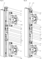
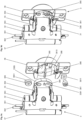
- Fig.2 shows the first hinge device 2 of Fig.1 with a part of the first door element 111 of the folding door 11 in a preferred embodiment.
- the door element 11 is held by mounting parts 38 of the stop hinge 3 and the auxiliary hinge 3 ' .
- the mounting parts 38 are preferably designed as hinge cups, but can also have other shapes.
- the stop profile 21 is connected at the top to an upper support track 5, which is guided in an upper support rail 12 by means of support rollers 51 and guide rollers 52.
- the stop profile 21, as in Fig.1 shown also connected on the underside to a support carriage 5 ' , which is guided in a lower support rail 12 ' .
- the support carriage 5 has a carriage body 50, which is provided on the underside with a connecting part 53, which in this embodiment is in a mounting channel 211 (see Fig. 6a ) of the stop profile 21.
- the displacement device 19, which can be designed as desired, is in Fig.2 not shown.
- the stop hinge 3 is placed with the stop body 30 on the support device 22 and the holding devices 24 are moved against the stop bodies 30 of the stop hinge 3 and the auxiliary hinge 3 ' in order to hold them in a form-fitting manner.
- the stop profile 21 has an outwardly open anchor channel 210 with profile elements that define a relatively narrow slot and enable the holding of anchor elements.
- the Figures 6a and 6b show that the support device 22 has a support body 220 which comprises a support anchor 2201 which is displaceable in the anchor channel 210 and lockable with at least one locking screw 2208.
- the support device 22 comprises a slider 221, which is displaceably mounted in the support body 220, and an actuating element 225, which is provided for displacing and holding the slider 221.
- the holding device 24 has a holding body 240 which comprises a holding anchor 2401 which is slidably held in the anchor channel 210, as well as a holding element 241 which can engage in a form-fitting manner in the stop body 30 of the stop hinge 3 or the auxiliary hinge 3 ' or can partially enclose the stop body 30.
- the holding body 240 is made of metal or preferably of plastic, such as polyoxymethylene POM.
- the retaining anchor 2401 is formed by the side pieces of the holding body 240.
- the retaining anchor 2401 of the plastic-made holding body 240 is additionally provided with lateral extensions 24011, which act as arresting elements to prevent the holding device 24 from moving automatically.
- lateral extensions 24011 which act as arresting elements to prevent the holding device 24 from moving automatically.
- recesses 24000 are provided in the holding body 240.
- the retaining anchor 2401 therefore has four spring-elastic held locking elements 24011, which can exert a force laterally outwards.
- the holding element 241 is fork-shaped and arranged at the upper end of the holding device 24.
- the holding body 240 is an elongated plate which is provided on the top and bottom with threaded parts 2408 which are arranged at a distance from each other which corresponds to the distance between two stop screws 308 which are inserted into the stop body 30 of the stop hinge 3 or auxiliary hinge 3 ' .
- the threaded parts 2408 can be machined into the holding body 240 with a thread cutter or can be inserted and cast as metal pieces in receiving openings 2400, as Fig. 4a shows.
- Fig.2 In a first installation step, the stop hinge 3 was already placed on the support device 22. In a second installation step, the holding devices 24 were moved against the stop bodies 30 of the stop hinge 3 and the auxiliary hinge 3' in order to hold and secure them in a form-fitting manner. The adjustment of the hinge device 2 can now be carried out easily.
- a first step A the adjusting element 225 of the support device 22 is actuated by means of a tool in order to move the stop hinge 3 and thus the door element 111 vertically to the desired height.
- a second step B the stop screws 308 are tightened, which are screwed into the threaded parts 2408 of the holding devices 24 in order to firmly connect the stop hinge 3 and the auxiliary hinge 3 ' each to the associated holding device 24. After this process, the stop hinge 3 and the auxiliary hinge 3 ' are firmly connected to the stop profile 21.
- a third step C an eccentric body 385 provided in the stop hinge 3 and in the auxiliary hinge 3 ' is actuated in order to move the mounting part 38 perpendicular to the stop profile 21. This allows the distance of the door element 111 from the stop profile 21 to be adjusted. In addition, the door element 111 can be aligned exactly vertically.
- the mounting part 38 is locked in a fourth step D by tightening a fixing screw 381.
- a fixing screw 381 Preferably, the stop hinge 3 and the auxiliary hinge 3 ' , which are preferably identical, are adjusted before the fixing screws 381 are tightened.
- a preferably provided stop screw 315 on the stop hinge 3 and on the auxiliary hinge 3 ' can also be actuated in order to limit the maximum deflection of the door element 111.
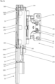
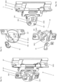
- Fig. 3a shows the hinge device 2 of Fig.2 with the stop hinge 3 detached from the stop profile 21 and the auxiliary hinge 3 ' detached from the stop profile 21 in a preferred embodiment.
- the stop screws 308 were loosened and the holding devices 24 were moved upwards into a position in which they are held.
- the hinges 3, 3 ' and the door element 111 connected to them could thus be removed.
- a coupling carriage 23 is provided with a carriage body 230 which comprises a carriage anchor 2301 (see Fig. 6a and Fig. 6b ), which is held displaceably in the anchor channel 210 of the stop profile 21 and which rests against the top of the slide 221.
- the coupling slide 23 is also displaced vertically together with the slide 221.
- the stop body 30 of the stop hinge 3 is therefore not placed directly on the slide 221, but on the coupling slide 23.
- the slide 221 therefore only has to absorb vertically acting forces and is thus protected against disruptive forces.
- the coupling device 23 is provided with a coupling element 231 which can engage in the coupling body 30 of the stop hinge 3 in order to hold it in a form-fitting manner.
- the support device 22 Before inserting the hinges 3, 3 ', the support device 22 is set to the intended height and fixed by tightening the locking screws 2208 of the support body 220, which are clamped to the stop profile 21. Any remaining height deviation can now be corrected after the assembly of the door element 111 by adjusting the support device 22.
- Fig. 3b shows the hinge device 2 of Fig. 3a with the stop hinge 3 and the auxiliary hinge 3 ' after connection with the stop profile 21.
- the holding devices 24 were moved downwards. After completion of the height adjustment, the stop screws 308 are finally tightened.
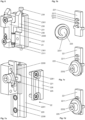
- Fig. 4a shows the hinge device 2 of Fig. 3a only with the stop hinge 3, without the stop profile 21 and the auxiliary hinge 3'.
- the holding element 241 of the holding device 24 and the coupling element 231 of the coupling device 23 are fork-shaped and can engage in a form-fitting manner in recesses 300 which are provided on both sides of the end pieces of the stop body 30.
- the stop body 30 is connected by lever shafts to a first end piece of a drive lever 31 and a first end piece of an adjusting lever 32, the second end pieces of which are connected by further lever shafts to a mounting lever 33.
- the mounting lever 33 is connected to a mounting body 338 on which the mounting part 38 is mounted so that it can be moved and locked.
- Fig. 4b shows part of the stop hinge 3 of Fig. 4a with the stop body 30, which has recesses 300 on a lower end piece into which the coupling carriage 23 can engage with coupling elements 231 in a form-fitting manner, and which has recesses 300 on an upper end piece into which the holding device 24 can engage with holding elements 241 in a form-fitting manner. Also shown is the first lever shaft 361, which is provided for holding the drive lever 31, and the second lever shaft 362, which is provided for holding the adjusting lever 32. The drive lever 31 and the adjusting lever 32 are cut in the middle.
- a drive spring 35 which encloses the first lever shaft 361 and which has two spring assemblies 353 (only one shown), which are connected to one another on one side by a spring center piece 352 and which each have a spring end piece 351 at the other end.
- the spring end pieces 351 are anchored to the stop body 30, while the spring center piece 352 is connected to the drive lever 31.
- Fig. 5a shows the left side of the hinge device 2 of Fig. 4a without the stop profile 21. It is shown that the coupling element 231 of the coupling slide 23 and the holding element 241 of the holding device 24 engage in the corresponding recesses 300 of the stop body 30.
- Fig. 5b shows a longitudinal section through the hinge device 2 of Fig. 5a .
- the stop screws 308 are screwed into the threaded parts 2408 of the holding body 240, so that the stop hinge 3 is firmly connected to the holding device 24.
- the section through the stop body 30 reveals a view of a damping element 37, which is located in a damping chamber 3000 of the stop body 30 and is held axially displaceably by a bearing plate 3001.
- the damping element 37 comprises a damping cylinder 371 and a damping piston 374 guided therein, which is connected to a piston rod 372, as well as a transmission part 373 which is connected to the damping cylinder 371 and has a guide flank 3730 facing away from the damping cylinder 371.
- the drive lever 31 has an actuating arm 317 which, when the drive lever 31 rotates, acts on the transmission part 373 and axially displaces the damping cylinder 371, while the piston rod 372 rests against a stop 3002 within the damping chamber 3000.
- a bearing channel 2300 is provided in the slide body 230, in which the coupling element 231, which rests against a support spring 232, is slidably mounted and can be completely or partially sunk into the slide body 230.
- the stop body 30 of the stop hinge 3 is guided against the coupling element 231, the latter is displaced into the coupling body 230 until it can be pushed back into a recess 300 of the stop body 30 by the support spring 232.
- the coupling device 23 further comprises a cover 236 which is connected to the coupling body 230 by at least one locking screw 2361.
- the cover 236 can also form a wall of the bearing channel 2300.
- the support body 220 of the support device 22 comprises a slide channel 2200 in which the slide 221 is mounted so as to be axially displaceable, and an actuating chamber 2250 within which the actuating element 225 is rotatably held.
- the actuating element 225 is provided in a force-fitting or integral manner with an eccentrically arranged eccentric part or an eccentrically running eccentric part which is in contact with the slide 221 or a part thereof.
- Fig. 5b further shows that the support body 220 and the slide body 230 in this preferred embodiment are optionally connected to one another by a connecting bolt 239.
- the bolt head 2391 of the connecting bolt 239 is slidably held within the carriage body 230 in a bolt chamber 2390 so that the coupling device 23 can be displaced from the support device 22 by the required amount.
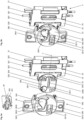
- Fig. 6a shows the hinge device 2 of Fig. 4a in exploded view with sections of the stop profile 21, but without the stop hinge 3. It is shown that the support anchor 2201, the slide anchor 2301 and the holding anchor 2401 are held in a form-fitting manner in the anchor channel 210 of the stop profile 21.
- Fig. 6b shows the hinge device 2 of Fig. 6a from the other side without the sections of the stop profile 21.
- Fig. 7a shows the adjustable support device 22 of Fig. 3a with the support body 220, which has the support anchor 2201 and the slide 221 which is mounted axially displaceably in the support body 220 and which can be displaced by means of the adjusting element 225.
- the cover 226 and the connecting screws 2261 are detached from the support body 220 so that the slide channel 2200 is exposed.
- the cover 226 therefore forms a side wall of the slide channel 2200.
- Fig. 7b shows the slider 221 of Fig. 7a , which has track segments 2211, and the actuating element 225, which is provided with a spiral 2251. Between the track segments 2211, guide tracks 2210 are formed, into which the spiral 2251 can engage.
- Fig. 7c shows the actuator 225 with the almost fully extended slide 221 of Fig. 7a .
- Fig. 7d shows the slider 221 of Fig. 7c after turning the adjusting element 225 counterclockwise.
- Fig.8 shows the coupling slide 23 of Fig. 3a with a cover 236 which is held by locking screws 2361 and which is shown in a sectional view, looking at the fork-shaped coupling element 231 which, in this preferred embodiment, is slidably mounted and supported by a spring 232.
- the coupling element 231 is partially extended from the bearing channel 2300. The exposed space in the bearing channel 2300 shows that the coupling element 231 can be completely slid into the carriage body 230.
- the coupling element 231 can also be integrally connected to the carriage body 230 in a form-fitting or force-fitting manner.
- the slide device 23 is manufactured in one piece, for example as a cast part.
- Fig. 9a shows the stop hinge 3 of Fig. 3a without stop body 30.
- the stop hinge 3 is shown in an exploded view.
- Fig. 9a and Fig.10 show that the stop hinge 3 has four lever shafts 361, 362, 363, 364, by means of which the stop body 30, a first drive lever 31, an adjusting lever 32 and an assembly lever 33 are connected to one another.
- the mounting lever 33 is connected to a mounting body 338 from which the mounting part 38 has been detached and in which an eccentric chamber 3385 and a screw chamber 3381 are provided.
- the mounting part 38 and the mounting body 338 can be connected to one another in a form-fitting manner and can be moved relative to one another and for this purpose have guide elements 386, 3386 that correspond to one another and running surfaces that lie against one another.
- the mounting body 338 has a guide groove 3386 into which a guide rib 386 connected to the mounting part 38 can engage.
- the guide elements can be designed as desired and can be provided as required.
- the mounting part 38 comprises a mounting plate 388 in which a longitudinal opening 3810 running parallel to the displacement axis y and a guide channel 3801 running perpendicular or inclined to the displacement axis y are provided.
- a cylindrical eccentric body 385 is mounted so as to be rotatable about a rotation axis x.
- the eccentric body 385 holds an eccentric part 3851 at a distance from the rotation axis x, which is rod-shaped or cylindrical and engages in the guide channel 3801.
- a fixing screw 381 is held, which can be guided through the longitudinal opening 3810 and connected on the other side with a lock nut in order to firmly connect the mounting part 38 to the mounting body 338.
- the longitudinal opening 3810 is surrounded by a guide track 38100 which is recessed into the mounting plate 388.
- the guide track 38100 is rectangular and is intended to keep the lock nut 3811 movable but not rotatable.
- the fixing screw 381 can therefore be tightened without the lock nut 3811 rotating.
- the guide channel 3801 is part of an engagement opening 380, which has a receiving opening 3800 adjoining the guide channel 3801, the dimensions of which preferably correspond to the dimensions of the eccentric body 385.
- the receiving opening 3800 preferably has at least one guide edge 3802, along which the eccentric part 3851 guided into the receiving opening 3800 can be introduced into the guide channel 3801 when the mounting part 38 is moved.
- the mounting part 38 can therefore be placed on the mounting body 338 and moved along the displacement axis y, whereby the eccentric part 3851 is automatically guided into the guide channel 3801.
- the engagement opening 380 can be covered by a closure part 39 which has a cover 390 and a closure body 391 by means of which the guide channel 3801 can be closed.
- the eccentric part 3851 is held within the guide channel 3801.
- the closure part 39 is also provided with clamp elements which can engage over the edge of the engagement opening 380 and hold the closure part 39 in position. It is also shown that the cover 390 can be sunk into a recess in the mounting plate 388.
- Fig. 9b shows the stop hinge of Fig. 9a without stop body 30 and with mounted mounting part 38.
- the eccentric part 3851 is held in the guide channel 3801.
- the fixing screw 381 is guided through the longitudinal opening 3810 and connected to the lock nut 3811.
- Fig. 9c shows the stop hinge 3 of Fig. 9a without stop body 30 and with loosened mounting part 38.
- the eccentric body 385 and the fixing screw 381 have been removed from the mounting body 388 and are shown separately.
- Fig. 9d shows the stop hinge of Fig. 9c without stop body 30 and with mounted mounting part 38.
- Fig.10 shows the stop hinge 3 of Fig. 9a in exploded view.
- the dot-dash lines symbolize how the stop body 30, the drive lever 31, the adjusting lever 32 and the assembly lever 33 are connected to one another using the four lever shafts 361, 362, 363, 364.
- the fixing screw 381 is inserted into the assembly body 338 from the rear, as shown.
- the eccentric body 385 is inserted into the assembly body 338 from the front, as shown.
- Fig. 11a shows the stop hinge 3 of Fig. 3a in a preferred embodiment with a stop body 30 ' , which is provided for positive engagement in the stop profile 21.
- the stop body 30 ' is provided with claw-shaped end pieces that can engage in the stop profile 21, provided that this is provided with corresponding profile parts. Threaded bolts can be inserted into the openings shown, which are clamped to the stop profile 21 in order to fix the stop hinge 3.
- the stop body 30 ' also preferably has a damping chamber 3000 into which the damping element 37 can be inserted.
- the stop body 30, for example according to Fig. 4b can therefore be stopped by the stop body 30 ' from Fig. 11a be replaced and vice versa.
- Fig. 11b shows the stop hinge 3 of Fig. 11a with the mounting part 38 detached and a closure element 39, by means of which the access opening 3850 can be closed.
- Fig. 11c shows the mounting part 38 and the locking element 39 of Fig. 11b from the other side.
Landscapes
- Engineering & Computer Science (AREA)
- Mechanical Engineering (AREA)
- Hinges (AREA)
Priority Applications (1)
| Application Number | Priority Date | Filing Date | Title |
|---|---|---|---|
| EP23160072.7A EP4424960A1 (fr) | 2023-03-03 | 2023-03-03 | Dispositif de charnière, charnière de butée et unité fonctionnelle |
Applications Claiming Priority (1)
| Application Number | Priority Date | Filing Date | Title |
|---|---|---|---|
| EP23160072.7A EP4424960A1 (fr) | 2023-03-03 | 2023-03-03 | Dispositif de charnière, charnière de butée et unité fonctionnelle |
Publications (1)
| Publication Number | Publication Date |
|---|---|
| EP4424960A1 true EP4424960A1 (fr) | 2024-09-04 |
Family
ID=85505631
Family Applications (1)
| Application Number | Title | Priority Date | Filing Date |
|---|---|---|---|
| EP23160072.7A Pending EP4424960A1 (fr) | 2023-03-03 | 2023-03-03 | Dispositif de charnière, charnière de butée et unité fonctionnelle |
Country Status (1)
| Country | Link |
|---|---|
| EP (1) | EP4424960A1 (fr) |
Cited By (1)
| Publication number | Priority date | Publication date | Assignee | Title |
|---|---|---|---|---|
| US20220307305A1 (en) * | 2019-12-19 | 2022-09-29 | Julius Blum Gmbh | Guide device for guiding a furniture part |
Citations (4)
| Publication number | Priority date | Publication date | Assignee | Title |
|---|---|---|---|---|
| EP2246509B1 (fr) * | 2009-04-28 | 2012-09-19 | Hawa Ag | Dispositif de déplacement pour éléments de séparation maintenus de manière rotative et élément de mobilier |
| US9284761B2 (en) | 2012-12-05 | 2016-03-15 | Hawa Ag | Displacement device for slidable and turnable separation elements and functional entity |
| EP2655768B1 (fr) * | 2010-12-03 | 2016-08-03 | Bortoluzzi Sistemi S.p.A. | Dispositif pour une porte rétractable latéralement, en particulier pour des meubles |
| EP4124715A1 (fr) * | 2021-07-30 | 2023-02-01 | Alpac S.r.l. | Structure de cadre pour la finition et l'équipement d'une ouverture d'un mur extérieur d'un bâtiment et procédé d'installation de ladite structure de cadre |
-
2023
- 2023-03-03 EP EP23160072.7A patent/EP4424960A1/fr active Pending
Patent Citations (5)
| Publication number | Priority date | Publication date | Assignee | Title |
|---|---|---|---|---|
| EP2246509B1 (fr) * | 2009-04-28 | 2012-09-19 | Hawa Ag | Dispositif de déplacement pour éléments de séparation maintenus de manière rotative et élément de mobilier |
| US8336972B2 (en) | 2009-04-28 | 2012-12-25 | Hawa Ag | Displacement device for pivotally held separation elements and article of furniture |
| EP2655768B1 (fr) * | 2010-12-03 | 2016-08-03 | Bortoluzzi Sistemi S.p.A. | Dispositif pour une porte rétractable latéralement, en particulier pour des meubles |
| US9284761B2 (en) | 2012-12-05 | 2016-03-15 | Hawa Ag | Displacement device for slidable and turnable separation elements and functional entity |
| EP4124715A1 (fr) * | 2021-07-30 | 2023-02-01 | Alpac S.r.l. | Structure de cadre pour la finition et l'équipement d'une ouverture d'un mur extérieur d'un bâtiment et procédé d'installation de ladite structure de cadre |
Cited By (2)
| Publication number | Priority date | Publication date | Assignee | Title |
|---|---|---|---|---|
| US20220307305A1 (en) * | 2019-12-19 | 2022-09-29 | Julius Blum Gmbh | Guide device for guiding a furniture part |
| US12590483B2 (en) * | 2019-12-19 | 2026-03-31 | Julius Blum Gmbh | Guide device for guiding a furniture part |
Similar Documents
| Publication | Publication Date | Title |
|---|---|---|
| EP3889381B1 (fr) | Meuble | |
| EP3603449B1 (fr) | Glissière pour tiroir | |
| EP3969703B1 (fr) | Système de guidage pour guider au moins un battant de porte | |
| DE102009025890A1 (de) | Vorrichtung zur Befestigung einer Frontblende an einer Seitenzarge eines beweglichen Möbelteils eines Möbels, Schubkasten und Möbel | |
| EP3580418A1 (fr) | Charnière pour meuble facile à monter | |
| DE202017100971U1 (de) | Montagevorrichtung zum Einsetzen von Rahmenelementen in Wandöffnungen | |
| WO2007009899A1 (fr) | Element d'amortissement | |
| WO2004082431A1 (fr) | Tiroir | |
| AT523327A1 (de) | Führungsvorrichtung zur Führung eines Möbelteils | |
| EP2799651A1 (fr) | Ferrure de porte coulissante pour meuble | |
| EP4424960A1 (fr) | Dispositif de charnière, charnière de butée et unité fonctionnelle | |
| EP3147440B1 (fr) | Dispositif d'insertion pour portes coulissantes | |
| WO2016138993A1 (fr) | Réglage mixte en hauteur et en inclinaison pour glissières télescopiques de tiroir | |
| EP3880924B1 (fr) | Meuble avec dispositif pour le guidage d'au moins une porte pliante-coulissante | |
| WO2025056287A1 (fr) | Ferrure de porte coulissante et agencement de porte coulissante associé | |
| WO2025185823A1 (fr) | Dispositif de charnière, charnière de butée et unité fonctionnelle | |
| AT501777A2 (de) | Schubladenführung | |
| EP4459091A1 (fr) | Dispositif de guidage, unité de guidage et unité fonctionnelle | |
| DE10105847B4 (de) | Mitnahmevorrichtung für ausziehbaren Möbelboden | |
| DE202017105849U1 (de) | Liftbeschlag für einen Möbelauszug | |
| EP2527575B1 (fr) | Ferrure de porte coulissante | |
| DE102010008597B3 (de) | Tür für einen Geräteschrank | |
| EP3286395A1 (fr) | Ferrure pour porte coulissante et procédé de montage d'une ferrure de guidage | |
| DE2821101C3 (de) | Auszugführung für in einem Gestell gehaltene Schubladen o.dgl | |
| AT526952B1 (de) | Führungsanordnung zur Führung eines bewegbaren Möbelteils |
Legal Events
| Date | Code | Title | Description |
|---|---|---|---|
| PUAI | Public reference made under article 153(3) epc to a published international application that has entered the european phase |
Free format text: ORIGINAL CODE: 0009012 |
|
| STAA | Information on the status of an ep patent application or granted ep patent |
Free format text: STATUS: THE APPLICATION HAS BEEN PUBLISHED |
|
| AK | Designated contracting states |
Kind code of ref document: A1 Designated state(s): AL AT BE BG CH CY CZ DE DK EE ES FI FR GB GR HR HU IE IS IT LI LT LU LV MC ME MK MT NL NO PL PT RO RS SE SI SK SM TR |
|
| STAA | Information on the status of an ep patent application or granted ep patent |
Free format text: STATUS: REQUEST FOR EXAMINATION WAS MADE |
|
| 17P | Request for examination filed |
Effective date: 20250304 |