EP1516675A2 - Distributeur de fluides - Google Patents
Distributeur de fluides Download PDFInfo
- Publication number
- EP1516675A2 EP1516675A2 EP04255428A EP04255428A EP1516675A2 EP 1516675 A2 EP1516675 A2 EP 1516675A2 EP 04255428 A EP04255428 A EP 04255428A EP 04255428 A EP04255428 A EP 04255428A EP 1516675 A2 EP1516675 A2 EP 1516675A2
- Authority
- EP
- European Patent Office
- Prior art keywords
- housing
- handle
- pump assembly
- fluid
- dispenser
- Prior art date
- Legal status (The legal status is an assumption and is not a legal conclusion. Google has not performed a legal analysis and makes no representation as to the accuracy of the status listed.)
- Withdrawn
Links
Images


Classifications
-
- B—PERFORMING OPERATIONS; TRANSPORTING
- B05—SPRAYING OR ATOMISING IN GENERAL; APPLYING FLUENT MATERIALS TO SURFACES, IN GENERAL
- B05B—SPRAYING APPARATUS; ATOMISING APPARATUS; NOZZLES
- B05B11/00—Single-unit hand-held apparatus in which flow of contents is produced by the muscular force of the operator at the moment of use
- B05B11/01—Single-unit hand-held apparatus in which flow of contents is produced by the muscular force of the operator at the moment of use characterised by the means producing the flow
- B05B11/10—Pump arrangements for transferring the contents from the container to a pump chamber by a sucking effect and forcing the contents out through the dispensing nozzle
- B05B11/1001—Piston pumps
- B05B11/1009—Piston pumps actuated by a lever
- B05B11/1011—Piston pumps actuated by a lever without substantial movement of the nozzle in the direction of the pressure stroke
Definitions
- the invention relates generally to fluid material dispensers and more particularly to dispensers having manually operable pumping mechanisms for dispensing condiments, lotions and similar fluids.
- Manually operated condiment dispensers are commonly used in restaurants, food stands and in commercial food preparation applications to dispense ketchup, mustard, etc.
- Known dispensers include manually operable pumps for dispensing condiments from a container through a spout.
- a single pump stroke dispenses a pre-determined amount of condiment equal to a single serving size portion.
- dispensers are not only difficult to manipulate, but they also increase the risk that liquid will spill onto the floor or countertop, as the user must concentrate on the pump instead of the liquid pouring out of the end. Reaching over with one hand also brings the user in closer contact with the dispensing end, increasing the risk that liquid will spill on the user's clothing, especially when the dispensing end is moving, as in U.S. Patent No. 5,381,932.
- the selected embodiment relates to a fluid dispenser comprising a pump assembly for receiving fluid to be dispensed and being responsive to a displacement input to pump fluid.
- An elongated housing is connected to the pump assembly and delivers fluid from the pump assembly.
- a handle is pivotally connected to the housing.
- a mechanical connection between the handle and the pump assembly provides the displacement input to the pump assembly when the handle is pivoted so that a mechanical advantage is applied to the pump assembly.
- a fluid dispenser comprises a pump assembly having a base and a plunger, the plunger having a fluid outlet end and being reciprocable to pump fluid to the outlet end.
- An elongated housing having a fluid outlet end is connected to the base with the fluid outlet end of the plunger being positioned within, and reciprocable in the housing.
- a handle is pivotally connected to the housing.
- a mechanical connection is provided between the plunger and the handle for providing the reciprocable displacement when the handle is pivoted so that a mechanical advantage is applied to the pump assembly.
- a flexible tube connects the fluid outlet end of the plunger to the fluid outlet end of the housing so that when the handle is pivoted, fluid is delivered from the housing at a position unaffected by displacement of the plunger.
- FIG. 1 shows a fluid dispenser 10 usable with a fluid container as exemplified by a horizontal planar cover 12.
- cover 12 may be thin stainless steel, either employed as a lid to a fluid container or as a section fastened to a laminated counter top for delivery of a fluid such as a condiment.
- Dispenser 10 incorporates a pump assembly 14 in widespread use in the fluid dispensing business.
- Pump assembly 14 is also known in the trade as a pump engine which is generally regarded to be the functional essentials of a fluid pump without a decorative exterior and other cover.
- Pump assembly 14 comprises a base 16 having a plunger bore 18 and a pumping chamber 20 having a generally cylindrical shape. Housing 16 has a threaded section 22 adjacent an opening 24 in cover 12.
- a sleeve 26 is internally threaded and adapted to thread over base 16 to hold the lower side, as viewed in FIG. 1, against the inside surface of cover 12. Wings 28 are provided on sleeve 26 to facilitate threading and unthreading without a special tool.
- the lower end of pumping chamber 20 has an inlet housing 30 threaded into the open end 32 of pump housing 20.
- Inlet housing 30 has a shoulder 34 abutting the end 32 of pumping chamber 20 to fix the position of inlet housing 30.
- Inlet housing 30 has a spigot 36 which receives an elongated tube 38 adaptable to extend to the appropriate bottom section of the fluid container beneath cover 12.
- inlet housing 30 is designed to have an angled entry of inlet tube 38 so as to allow inlet tube 38 to extend generally vertically downward.
- Inlet housing 30 has an inlet orifice 40 connected to inlet tube 38 and having a check ball 42 seated on orifice 40 to permit flow only from inlet tube 38 through orifice 40 to ball chamber 44.
- a ball retention disk 46 with flow passages 47 (only one of which is shown) to pumping chamber 20, is received within the interior of pumping chamber 20 to maintain check ball 42 within the chamber 44.
- a plunger assembly 48 has a tubular plunger 50 extending through and beyond plunger bore 18. Integral with the lower end of plunger 50 is an annular piston 52 having an o-ring 54 slideable along the interior wall of pumping chamber 20 to provide pumping action.
- An outlet check valve assembly 56 is threaded into the end of the annular piston 52. With specific reference to FIG. 3, outlet check valve assembly 56 comprises an annular check valve holder 58 having threads 60 for connection to the annular piston 52.
- Check valve holder 58 has a serrated flange 62 to facilitate operator threading and unthreading without special tools.
- Holder 58 has an end face 64 with a plurality of circumferentially spaced openings 66 to provide fluid flow.
- An annular elastomeric fluid check valve 68 is positioned over wall 64 and is maintained in coaxial alignment by means of an integral center post 70 retained within central hole 72 of check valve holder 58. Thus, when fluid flow is from openings 66 past elastomeric valve 68, the valve 68 flexes to permit free flow but if the direction of flow is opposite will be retained against the openings 66 and prevent reverse flow.
- the plunger 50 extends through plunger bore 18 to an outlet cap 74 threaded over the end of plunger 50 at a threaded joint 76.
- Cap 74 has a tubular outlet section 78 connecting to a central chamber 80.
- a return spring 82 is positioned over plunger 50 and acts against a shoulder 84 in cap 74 and against an annular recess 86 in base 16. Spring 82 urges the plunger 50 to the illustrated ready position.
- Tubular outlet 78 connects with a flexible tube 88 extending to an outlet recess 90 integral with a lower housing 92.
- Lower housing 92 surrounds a portion of the pump assembly 14 and may provide a decorative cover for the unit in use.
- Lower housing 92 extends from section 90 to a lower flange 94 abutting the top of housing 16 and a lower flange 96 extending to an axial flange 98 received in housing 16 so that when sleeve 26 is threaded onto housing 16, flange 98 is captured to hold it in place.
- Housing 92 mates with an upper housing 100 through an overlapping joint (not shown) in FIG. 1 to extend beyond the plunger 50 to a second portion 102 of the housing.
- the second portion 102 extends to a base flange 104 and an axially extending flange 106 received in housing 16 so that when sleeve 26 is threaded and in place, housing 100 is captured in place.
- outlet spigot 108 functions to provide the ultimate outlet of fluid from the dispenser 10 through passage 110 which connects with a right angle passage 112 that is received over tube 114 of outlet section 90 of lower housing 92.
- outlet spigot 112 When outlet spigot 112 is installed over tube 114, a flange having an upper section at 114 curving to a lower section 116 slips over the end of housings 100 and 92, respectively, to hold them in place against one another.
- Outlet spigot 108 is manufactured so that it can be assembled in place to hold the housings together but pulled apart so that they may be separated as described later.
- handle assembly 118 to provide a mechanical advantage and facilitate stable dispensing of fluids.
- Handle assembly 118 is formed in a one-piece molded housing, although it may be fabricated in individual components as appropriate for manufacturing feasibility.
- handle 118 comprises a molded housing 120 having integral actuating section 122 leading to an operator handle 124.
- An insert 126 with an anti-friction surface may be employed to improve tactile manipulation of handle 118.
- Insert 126 may also be color coded to indicate the contents of the fluid container.
- the actuating section 122 has a central opening 128 to lighten handle 118 and to improve its stiffness.
- the actuating section 122 extends to an integral foot 130 which has a curved forward surface 132 extending to a flange 134 received within an opening 136 in upper housing 100.
- Foot 130 has side walls 138, only one of which is shown because of the section view of FIG. 1.
- Side walls 138 and flange 134 cooperate to define a curved surface 140, which abuts the head of cap 74.
- the handle 118 is pivoted in the second portion 102 of upper housing 100.
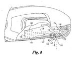
- Housing 120 of handle 118 has a pair of trunions 142, only one of which is shown in FIG. 5, which are positioned in opposed holes 144 in the second portion 102 of upper housing 100.
- a clip assembly 146 is provided in order to provide for removable retention and journaling of handle 118.
- Clip assembly 146 has one portion shown in FIG. 5 and a mirror portion, shown in FIG. 1 and FIG. 2, to journal respective trunions 142.
- Clip 146 has a journal section 148 comprising a circular recess 150 for receiving each trunion 142.
- the journal section 148 has a ramp 152 in the direction extending away from the pumping element 14 for assembly purposes, as will be described later.
- Clip assembly 146 may be formed from material having superior lubricity like a high density polyethylene.
- a flexible C center section 154 permits the clip to be compressed for insertion and then to expand into holes 144 to embrace the trunions 142.
- the flexible center section 154 is compressed by operator manipulation of a pair of fingers 156.
- the fingers 156 are positioned so that they overlap one another when both are moved toward the centerline of the housing.
- ribs 158 and 160 are provided on fingers 156.
- the rib 158 extends the length of the finger 156 and the ribs 160 are triangular and extend a short distance from the free end of finger 156.
- the fingers as shown in FIG. 5 are on its bottom side and the mirror finger shown in FIG. 1 has ribs 158 and 160 on the top side. This is so the ribs 158 and 160 will not interfere with compression of the fingers and therefore the C section 154 when the fingers are compressed to permit removal of handle assembly 118.
- the dispenser 10 is now in a position to deliver fluid.
- a customer simply depresses handle 118 by grasping the free end adjacent insert 126 and depressing it downward to the position shown in FIG. 2. Because of the curvature of flange 134 and side walls 138 where they contact the flat top of plunger cap 74, side loading on plunger 50 is minimized, if not eliminated. This greatly decreases any plunger binding.
- the delivery end of the housing projects to a fluid delivery end away from pump assembly 14 and the pivot point of the handle 118 extends in an opposite direction. This permits a maximum mechanical advantage to be applied by handle 118 to the pump assembly plunger 50 while minimizing the overall envelope of the dispenser 10. It should also be noted that because the pump assembly is angled with respect to the cover 12, the outlet spigot 108 is elevated above the cover 12 sufficiently to permit both a food object such as a hot dog and a customer's hand to be placed underneath the outlet spigot 108. It should also be noted that the direction of displacement of the plunger 50 is generally perpendicular to a line between the outlet end of the housing and the pivot point for the handle, the line forming an acute angle with respect to the cover 12.
- the unit as presented to a customer has a clean appearance without the motion of the movable plunger. This permits a standard high-volume, low cost pump assembly to be in incorporated in a unit that has premium features with an easily manipulatable handle and minimum of moving parts.
- the fluid dispenser 10 may be field stripped without any special tools.
- the wings 28 on sleeve 26 permit an operator to apply sufficient force to unthread sleeve 26, thus permitting housing 16 to be removed from cover 12, the spigot 108 removed from the delivery end of the unit and the upper and lower housings 100 and 92 to be removed from one another to provide cleaning.
- the ribs 158 and 160 on the clip 146 are squeezed together to clear the trunions 142 and permit the handle 118 to be removed in a direction straight to the right as shown in FIG. 1.
- the only position handle 118 can be in to achieve this is in the fully extended ready position as shown in FIG. 1. Once the handle has been pivoted as if to begin a pumping stroke, as shown in FIG. 2, the curved side walls 138 prevent removal of the handle 118.
- FIGS. 1 through 5 has a mechanical interface between the handle 118 and the plunger head 74 that operates only in a direction to depress plunger 50.
- the spring 82 provides adequate return to bring the handle 118 back to its ready position and lip 134 prevents the handle 118 from being pivoted out of the housing..
- the interconnection shown in FIG. 6 may be employed.
- FIG. 6 shows a fragmentary view of the fluid dispenser of FIG. 1 with a focus only on the interconnection of the cap 74 of plunger 50 to the foot 130 of handle 118. In this case, like reference characters will be used for corresponding parts but with a prime.
- head 74' has an integral T head 162, which incorporates a flanged section 164, received in a slot 166 of the curved forward wall 132' of foot 130'.
Landscapes
- Reciprocating Pumps (AREA)
- Containers And Packaging Bodies Having A Special Means To Remove Contents (AREA)
Applications Claiming Priority (4)
| Application Number | Priority Date | Filing Date | Title |
|---|---|---|---|
| US933963 | 1978-08-15 | ||
| US50432703P | 2003-09-19 | 2003-09-19 | |
| US504327P | 2003-09-19 | ||
| US10/933,963 US7377408B2 (en) | 2003-09-19 | 2004-09-03 | Fluid dispenser |
Publications (2)
| Publication Number | Publication Date |
|---|---|
| EP1516675A2 true EP1516675A2 (fr) | 2005-03-23 |
| EP1516675A3 EP1516675A3 (fr) | 2008-03-12 |
Family
ID=34198312
Family Applications (1)
| Application Number | Title | Priority Date | Filing Date |
|---|---|---|---|
| EP04255428A Withdrawn EP1516675A3 (fr) | 2003-09-19 | 2004-09-08 | Distributeur de fluides |
Country Status (4)
| Country | Link |
|---|---|
| US (1) | US7377408B2 (fr) |
| EP (1) | EP1516675A3 (fr) |
| CN (1) | CN1651319A (fr) |
| CA (1) | CA2481645A1 (fr) |
Cited By (1)
| Publication number | Priority date | Publication date | Assignee | Title |
|---|---|---|---|---|
| WO2015112937A1 (fr) * | 2014-01-27 | 2015-07-30 | Gojo Industries, Inc. | Distributeur et unité de recharge présentant un tube de sortie pouvant s'aplatir |
Families Citing this family (21)
| Publication number | Priority date | Publication date | Assignee | Title |
|---|---|---|---|---|
| US7556179B2 (en) * | 2005-09-19 | 2009-07-07 | Simplehuman Llc | Soap dispensing apparatus |
| US20070062975A1 (en) * | 2005-09-19 | 2007-03-22 | Frank Yang | Soap dispensing apparatus |
| USD530955S1 (en) | 2006-04-13 | 2006-10-31 | Simplehuman Llc | Soap dispenser |
| CN100537047C (zh) * | 2006-08-18 | 2009-09-09 | 旭通模具有限公司 | 压头泵结构 |
| USD554412S1 (en) | 2006-12-12 | 2007-11-06 | Simplehuman Llc | Studio soap pump |
| USD554411S1 (en) | 2006-12-12 | 2007-11-06 | Simplehuman Llc | Ceramic soap pump |
| JP4355780B2 (ja) * | 2006-12-15 | 2009-11-04 | 哲也 多田 | トリガー式ポンプディスペンサー |
| US20110147419A1 (en) * | 2007-12-14 | 2011-06-23 | Atsushi Tada | Pressure accumulation dispenser |
| US20090281924A1 (en) * | 2008-02-29 | 2009-11-12 | Reliability Brands Llc | Label identification and management system for fluids |
| US7874463B2 (en) * | 2008-03-14 | 2011-01-25 | Gojo Industries, Inc. | Dispenser with collapsible dispensing tube |
| US20090291005A1 (en) * | 2008-05-20 | 2009-11-26 | Reliability Brands Llc | Manual pump for dispensing lubricants |
| KR101079725B1 (ko) * | 2009-07-15 | 2011-11-03 | 주식회사 엘지생활건강 | 유체용기의 펌핑장치 및 누름버튼 |
| US8814007B2 (en) * | 2010-12-31 | 2014-08-26 | Medline Industries, Inc. | Dispenser with directional flow controlling flange and corresponding systems |
| BR112013028398A2 (pt) * | 2011-05-03 | 2019-09-24 | Meadwestvaco Calmar Inc | distribuidores de líquidos e métodos para fabricaçãodos mesmos |
| KR101429615B1 (ko) * | 2013-03-21 | 2014-08-13 | 주식회사 함일셀레나 | 일액형 폴리우레탄 폼의 디스펜싱 어댑터 |
| US10549298B2 (en) * | 2017-05-25 | 2020-02-04 | Spectrum Brands, Inc. | Pivot-to-dispense soap pump |
| US10494249B1 (en) | 2018-07-31 | 2019-12-03 | Server Products, Inc. | Food product dispensers having levers with slidable pivot ends |
| EP3986618B1 (fr) | 2019-06-24 | 2026-04-01 | Rieke LLC | Pompe modulaire lavable |
| CN115461158B (zh) | 2020-03-03 | 2025-03-04 | 里克包装系统有限公司 | 大容量往复式分配器 |
| KR102479409B1 (ko) * | 2021-01-21 | 2022-12-19 | 엘지전자 주식회사 | 정수기 |
| CN114226097B (zh) * | 2021-12-27 | 2023-03-10 | 山东蓝天新材料科技有限公司 | 一种涂料喷涂装置 |
Family Cites Families (17)
| Publication number | Priority date | Publication date | Assignee | Title |
|---|---|---|---|---|
| US1466804A (en) * | 1921-12-22 | 1923-09-04 | Fingal C Orr | Liquid-dispensing apparatus |
| US1739195A (en) * | 1926-09-14 | 1929-12-10 | Beth H Wheeler | Nonreversible pump |
| US1947088A (en) * | 1930-07-07 | 1934-02-13 | Jiffy Lubricator Company | Adjustable and releasable pressure grease gun |
| US2113022A (en) | 1937-02-26 | 1938-04-05 | Hefti Hans | Dispensing device |
| CH348250A (fr) | 1958-08-06 | 1960-08-15 | Rossetti Charles | Appareil pour la distribution d'un produit pâteux |
| US3332585A (en) | 1966-03-23 | 1967-07-25 | Thomas E Cox | Adjustable syrup pump with pump casing within container |
| US3393840A (en) * | 1966-08-05 | 1968-07-23 | Edwin P. Sundholm | Miniaturized hand grease gun |
| JPS5153488Y2 (fr) | 1973-04-10 | 1976-12-21 | ||
| US5381932A (en) | 1992-04-14 | 1995-01-17 | American Wyott Corporation | Condiment pump |
| US5375746A (en) | 1993-05-10 | 1994-12-27 | Server Products, Inc. | Food pump having a cast valve body |
| US5332129A (en) * | 1993-06-16 | 1994-07-26 | Moen Incorporated | Soap dispenser assembly |
| US5482187A (en) * | 1993-09-13 | 1996-01-09 | Hygienix, Inc. | Dispenser for viscous substances |
| US5435463A (en) | 1993-12-23 | 1995-07-25 | Dci Marketing | Condiment dispenser |
| US5579959A (en) | 1995-05-16 | 1996-12-03 | Star Manufacturing International, Inc. | Viscous food products housing, pump, dispenser, and valve apparatus |
| US6019256A (en) | 1998-07-31 | 2000-02-01 | Melinda Carucci | Condiment pump |
| GB0110429D0 (en) * | 2001-04-27 | 2001-06-20 | Hornbeam Ivy Ltd | Pump assembly |
| US6454135B1 (en) * | 2001-09-18 | 2002-09-24 | Owens-Illinois Closure Inc. | Dual liquid dispensing packages |
-
2004
- 2004-09-03 US US10/933,963 patent/US7377408B2/en not_active Expired - Lifetime
- 2004-09-08 EP EP04255428A patent/EP1516675A3/fr not_active Withdrawn
- 2004-09-15 CA CA002481645A patent/CA2481645A1/fr not_active Abandoned
- 2004-09-20 CN CNA2004100798130A patent/CN1651319A/zh active Pending
Cited By (2)
| Publication number | Priority date | Publication date | Assignee | Title |
|---|---|---|---|---|
| WO2015112937A1 (fr) * | 2014-01-27 | 2015-07-30 | Gojo Industries, Inc. | Distributeur et unité de recharge présentant un tube de sortie pouvant s'aplatir |
| US9565977B2 (en) | 2014-01-27 | 2017-02-14 | Gojo Industries, Inc. | Dispensers and refill units having collapsible outlet tubes |
Also Published As
| Publication number | Publication date |
|---|---|
| US20050061835A1 (en) | 2005-03-24 |
| EP1516675A3 (fr) | 2008-03-12 |
| CN1651319A (zh) | 2005-08-10 |
| US7377408B2 (en) | 2008-05-27 |
| CA2481645A1 (fr) | 2005-03-19 |
Similar Documents
| Publication | Publication Date | Title |
|---|---|---|
| US7377408B2 (en) | Fluid dispenser | |
| US5165577A (en) | Disposable plastic liquid pump | |
| CN101512210B (zh) | 滑块阀配件和轴环 | |
| US6131767A (en) | Tap for dispensing fluid | |
| US10368701B2 (en) | Reservoir with removable mobile dispenser | |
| US7527174B2 (en) | Stationary soap dispenser assembly | |
| US5114048A (en) | Faucet assembly having integral liquid product dispenser | |
| US7798370B2 (en) | Universal collar key | |
| US6126046A (en) | Spigot adaptor | |
| CA2698915C (fr) | Pompe a tige stationnaire | |
| HK1039759A1 (en) | Liquid sprayer | |
| CA2911599C (fr) | Distributeur d'echantillon dote d'un berceau d'amorcage | |
| EP3061374B1 (fr) | Distributeur de liquide avec distributeur mobile amovible | |
| US7743948B2 (en) | Dispensing device | |
| US20190201926A1 (en) | Multi-nozzle multi-container fluid spray device | |
| US4493443A (en) | Multiposition valved dispenser | |
| RU2768351C2 (ru) | Раздаточная система | |
| TWI276783B (en) | Dosing device | |
| HK1081501A (en) | Fluid dispenser | |
| US10946393B2 (en) | Multi-nozzle multi-container fluid spray device | |
| US10494249B1 (en) | Food product dispensers having levers with slidable pivot ends | |
| HK1137797B (en) | Slider valve fitment and collar |
Legal Events
| Date | Code | Title | Description |
|---|---|---|---|
| PUAI | Public reference made under article 153(3) epc to a published international application that has entered the european phase |
Free format text: ORIGINAL CODE: 0009012 |
|
| AK | Designated contracting states |
Kind code of ref document: A2 Designated state(s): AT BE BG CH CY CZ DE DK EE ES FI FR GB GR HU IE IT LI LU MC NL PL PT RO SE SI SK TR |
|
| AX | Request for extension of the european patent |
Extension state: AL HR LT LV MK |
|
| PUAL | Search report despatched |
Free format text: ORIGINAL CODE: 0009013 |
|
| AK | Designated contracting states |
Kind code of ref document: A3 Designated state(s): AT BE BG CH CY CZ DE DK EE ES FI FR GB GR HU IE IT LI LU MC NL PL PT RO SE SI SK TR |
|
| AX | Request for extension of the european patent |
Extension state: AL HR LT LV MK |
|
| AKX | Designation fees paid |
Designated state(s): DE ES FR GB IT |
|
| STAA | Information on the status of an ep patent application or granted ep patent |
Free format text: STATUS: THE APPLICATION IS DEEMED TO BE WITHDRAWN |
|
| 18D | Application deemed to be withdrawn |
Effective date: 20080913 |