EP1516761A1 - Dispositif de chauffage électrique avec un capteur de température - Google Patents
Dispositif de chauffage électrique avec un capteur de température Download PDFInfo
- Publication number
- EP1516761A1 EP1516761A1 EP03021405A EP03021405A EP1516761A1 EP 1516761 A1 EP1516761 A1 EP 1516761A1 EP 03021405 A EP03021405 A EP 03021405A EP 03021405 A EP03021405 A EP 03021405A EP 1516761 A1 EP1516761 A1 EP 1516761A1
- Authority
- EP
- European Patent Office
- Prior art keywords
- temperature
- control circuit
- power
- predetermined
- circuit according
- Prior art date
- Legal status (The legal status is an assumption and is not a legal conclusion. Google has not performed a legal analysis and makes no representation as to the accuracy of the status listed.)
- Withdrawn
Links
Images



Classifications
-
- B—PERFORMING OPERATIONS; TRANSPORTING
- B60—VEHICLES IN GENERAL
- B60H—ARRANGEMENTS OF HEATING, COOLING, VENTILATING OR OTHER AIR-TREATING DEVICES SPECIALLY ADAPTED FOR PASSENGER OR GOODS SPACES OF VEHICLES
- B60H1/00—Heating, cooling or ventilating devices
- B60H1/22—Heating, cooling or ventilating devices the heat source being other than the propulsion plant
- B60H1/2215—Heating, cooling or ventilating devices the heat source being other than the propulsion plant the heat being derived from electric heaters
- B60H1/2225—Heating, cooling or ventilating devices the heat source being other than the propulsion plant the heat being derived from electric heaters arrangements of electric heaters for heating air
-
- B—PERFORMING OPERATIONS; TRANSPORTING
- B60—VEHICLES IN GENERAL
- B60H—ARRANGEMENTS OF HEATING, COOLING, VENTILATING OR OTHER AIR-TREATING DEVICES SPECIALLY ADAPTED FOR PASSENGER OR GOODS SPACES OF VEHICLES
- B60H1/00—Heating, cooling or ventilating devices
- B60H1/00642—Control systems or circuits; Control members or indication devices for heating, cooling or ventilating devices
- B60H1/00735—Control systems or circuits characterised by their input, i.e. by the detection, measurement or calculation of particular conditions, e.g. signal treatment, dynamic models
- B60H1/00764—Control systems or circuits characterised by their input, i.e. by the detection, measurement or calculation of particular conditions, e.g. signal treatment, dynamic models the input being a vehicle driving condition, e.g. speed
-
- B—PERFORMING OPERATIONS; TRANSPORTING
- B60—VEHICLES IN GENERAL
- B60H—ARRANGEMENTS OF HEATING, COOLING, VENTILATING OR OTHER AIR-TREATING DEVICES SPECIALLY ADAPTED FOR PASSENGER OR GOODS SPACES OF VEHICLES
- B60H1/00—Heating, cooling or ventilating devices
- B60H1/00642—Control systems or circuits; Control members or indication devices for heating, cooling or ventilating devices
- B60H1/00735—Control systems or circuits characterised by their input, i.e. by the detection, measurement or calculation of particular conditions, e.g. signal treatment, dynamic models
- B60H1/00807—Control systems or circuits characterised by their input, i.e. by the detection, measurement or calculation of particular conditions, e.g. signal treatment, dynamic models the input being a specific way of measuring or calculating an air or coolant temperature
-
- B—PERFORMING OPERATIONS; TRANSPORTING
- B60—VEHICLES IN GENERAL
- B60H—ARRANGEMENTS OF HEATING, COOLING, VENTILATING OR OTHER AIR-TREATING DEVICES SPECIALLY ADAPTED FOR PASSENGER OR GOODS SPACES OF VEHICLES
- B60H1/00—Heating, cooling or ventilating devices
- B60H1/02—Heating, cooling or ventilating devices the heat being derived from the propulsion plant
- B60H1/03—Heating, cooling or ventilating devices the heat being derived from the propulsion plant and from a source other than the propulsion plant
- B60H1/034—Heating, cooling or ventilating devices the heat being derived from the propulsion plant and from a source other than the propulsion plant from the cooling liquid of the propulsion plant and from an electric heating device
-
- B—PERFORMING OPERATIONS; TRANSPORTING
- B60—VEHICLES IN GENERAL
- B60H—ARRANGEMENTS OF HEATING, COOLING, VENTILATING OR OTHER AIR-TREATING DEVICES SPECIALLY ADAPTED FOR PASSENGER OR GOODS SPACES OF VEHICLES
- B60H1/00—Heating, cooling or ventilating devices
- B60H1/22—Heating, cooling or ventilating devices the heat source being other than the propulsion plant
- B60H1/2215—Heating, cooling or ventilating devices the heat source being other than the propulsion plant the heat being derived from electric heaters
- B60H1/2218—Heating, cooling or ventilating devices the heat source being other than the propulsion plant the heat being derived from electric heaters controlling the operation of electric heaters
-
- F—MECHANICAL ENGINEERING; LIGHTING; HEATING; WEAPONS; BLASTING
- F24—HEATING; RANGES; VENTILATING
- F24H—FLUID HEATERS, e.g. WATER OR AIR HEATERS, HAVING HEAT-GENERATING MEANS, e.g. HEAT PUMPS, IN GENERAL
- F24H9/00—Details
- F24H9/18—Arrangement or mounting of grates or heating means
- F24H9/1854—Arrangement or mounting of grates or heating means for air heaters
- F24H9/1863—Arrangement or mounting of electric heating means
- F24H9/1872—PTC resistor
-
- B—PERFORMING OPERATIONS; TRANSPORTING
- B60—VEHICLES IN GENERAL
- B60H—ARRANGEMENTS OF HEATING, COOLING, VENTILATING OR OTHER AIR-TREATING DEVICES SPECIALLY ADAPTED FOR PASSENGER OR GOODS SPACES OF VEHICLES
- B60H1/00—Heating, cooling or ventilating devices
- B60H1/00007—Combined heating, ventilating, or cooling devices
- B60H1/00021—Air flow details of HVAC devices
- B60H2001/00114—Heating or cooling details
- B60H2001/00128—Electric heaters
-
- B—PERFORMING OPERATIONS; TRANSPORTING
- B60—VEHICLES IN GENERAL
- B60H—ARRANGEMENTS OF HEATING, COOLING, VENTILATING OR OTHER AIR-TREATING DEVICES SPECIALLY ADAPTED FOR PASSENGER OR GOODS SPACES OF VEHICLES
- B60H1/00—Heating, cooling or ventilating devices
- B60H1/32—Cooling devices
- B60H2001/3286—Constructional features
- B60H2001/3288—Additional heat source
Definitions
- the invention relates to an electric heater, in particular as additional heating for motor vehicles.
- electric booster heaters are used for heating used by interior and engine.
- Such electric heaters are also suitable for other purposes, for example in the field of domestic installations, in particular room air conditioning, industrial plants and like.
- the normal heating system of a motor vehicle is connected to the engine cooling circuit and uses the engine waste heat to heat the vehicle interior.
- a water heat exchanger arranged. The heat exchanger heats the intake from the outside Air over the usually 80 ° C - 90 ° C warm cooling water. The heated air is then fed to the vehicle interior.
- the cooling water temperature corresponds when starting the engine the outside temperature. A warming of the Vehicle interior on the cooling water so that not possible, but only after a few minutes as soon as the cooling water has warmed up and the cooling water temperature well above the outside temperature.
- Electric booster heaters in the heating / air conditioning of a motor vehicle can not be the period of time in which the waste heat of the engine is available for heating purposes, to be bridged. Electric booster heaters reach their operating temperature within a few seconds and can thus heat the air flowing through accordingly.
- PTC heating elements are preferably used, to convert the electricity into heat.
- the PTC heating elements are equipped with radiator elements in thermally conductive connection. The of the PTC heating elements generated heat is released via the radiator elements to the air flowing through.
- the overall arrangement of a layered structure of PTC heating elements, Radiator elements and contact plates, which serve the power supply, is to increase the efficiency of a clamping pressure exposed.
- By the clamping is an improvement in the electrical and thermal contacting of the PTC heating elements reached.
- the electrical booster heaters typically have a power consumption in the range of 1,000 W to 2,000 W. With this power consumption is the motor vehicle electrical system burdened to a considerable extent. To the on-board network load so As low as possible, the auxiliary heater is switched off as soon as the Cooling water provides sufficient heating power over the water heat exchanger.
- a possible criterion used to shut off the electric booster heater can be is the cooling water temperature.
- a Temperature has reached about 80 ° C, is sufficient heating power over the Cooling water ready, so that the electric auxiliary heating be switched off can.
- cooling water temperature criterion may alternatively be a time criterion be used.
- the electric booster heater will after the start of the engine switched off as soon as a fixed period of time since the start of the engine has passed, for example five minutes.
- the electrical heating device is via a data bus, for example, a CAN or LIN bus, to a motor vehicle electrical system connected to the transmission of control and information signals.
- a data bus for example, a CAN or LIN bus
- the electric booster heaters in the on state a high power consumption in the range of 1,000 W to 2,000 W, is the vehicle electrical system correspondingly heavily loaded. So that the additional heater is no longer electric Draws power from the on-board network than is provided for it can, in addition, a corresponding signal of the electric auxiliary heater fed.
- the signal indicating the available electrical power will either be passed over the data bus of the heater or as a separate signal.
- the DF signal indicates the utilization of the vehicle generator on.
- the electric heating power can be adjusted be that the generator is never taken more power than this just created. Thus it can be successfully prevented, due to a negative Charge balance of the battery energy must be taken.
- a disadvantage of these conventional electrical booster heaters is that these be connected to external signal lines, in particular a data bus have to.
- the associated additional effort is just at the bottom of vehicles Price ranges disproportionately large, as different in these vehicle classes Variants of heating / air conditioning systems are used.
- Variants of heating / air conditioning systems are used.
- For one thing must inexpensive, simple systems, i. be connected to "manual" air conditioning, on the other hand, but also more complex, comfortable systems with a "climate control". So that for all variants of a heating / air conditioning a single additional heater version can be used, this is unnecessarily complicated and causes thus at the cheaper motor vehicles unnecessarily high costs.
- the object of the invention is therefore to provide a control circuit for operating a electric heater, an electric heater and a method indicate for operating an electric heater, in which the effort be reduced for coupling the heater to external control signals can.
- a control circuit for operating an electric heater, in particular as additional heating for a Motor vehicle specified.
- the heater includes PTC heating elements and a temperature sensor, which determines the temperature of the flowing into the heater Air detected.
- the control circuit includes a memory device for storage a predetermined temperature value.
- a comparator compares that of the Temperature sensor detected temperature with the stored temperature threshold.
- An activation device is used for release or interruption the power supply to the PTC heating elements in dependence on the comparison result of the comparator.
- a heating device in particular as additional heating for a motor vehicle, indicated.
- the heater contains PTC heating elements and a temperature sensor that measures the temperature of the Heater air flowing detected.
- the heater includes a control circuit for enabling or disabling power to the PTC heating elements.
- the control circuit includes a memory device, a comparator and an activation device.
- the storage device stores a predetermined temperature threshold, the comparator compares that of the Temperature sensor detected temperature with the stored temperature threshold and the activation device is used to enable or disable the Power supply to the PTC heating elements as a function of the comparison result of the comparator.
- a method for operating a electric heating device in particular as additional heating for a motor vehicle, specified.
- the heater includes PTC heating elements and a temperature sensor, which detects the temperature of the air flowing into the heater air. First, an actual temperature value of the flowing into the heater Air detected. Subsequently, the detected temperature value is stored with a fixed temperature threshold compared. Depending on the As a result, the power supply to the PTC heating elements is released or locked.
- the temperature of the flowing into the heater To capture air.
- the heating power of the heater in particular a Switching on / off, depending on the difference between the detected Temperature value of the incoming air and a stored, fixed temperature value controlled.
- the additional electric heater “itself" control without that an external signal must be supplied, for example indicates the cooling water temperature.
- the electrical connection of an electrical Additional heating in a motor vehicle to the vehicle electrical system simplified and a correspondingly cheaper version of the additional heating is possible.
- the connection to a data bus a motor vehicle electrical system are dispensed with.
- the information for switching on / off will depend solely on the temperature of the heater set flowing air and the control logic of the invention.
- the power supply to the PTC heating elements is released when the detected temperature falls below the stored temperature value.
- Electricity taken from the electrical system when there is actually a need for heating On external control signal or a signal supplied by the user are not required.
- the temperature threshold is in the range between 5 ° C and 15 ° C, most preferably between 8 ° C and 10 ° C. With these temperature values can ensure that the electric heater is turned on only then is when in the interior of the motor vehicle is actually a heating demand.
- the start of the motor vehicle is detected and the heater is turned on only when a heating demand when Switching on the motor vehicle is. This can easily in a simple way Waste heat of the motor vehicle engine are bridged when starting.
- the time is recorded since the Shutdown of the engine has elapsed. This can be easily determined whether the residual cooling water is sufficient to heat the interior.
- a predetermined period of time firmly stored.
- the predetermined value the supply of power to the PTC heating elements disabled.
- the predetermined period of time which is compared with the detected time duration lies preferably in the range of 1 to 5 hours, very preferably in the range between 2 to 3 hours. This can be easily ensured that the residual heat of the engine in deciding whether the electric heater is turned on, is taken into account.
- the stored temperature threshold value evaluated before comparison with the detected temperature of the supply air. This allows additional influences in addition to the air temperature in a simple manner on the assessment of whether the heater is to be turned on.
- the stored temperature threshold is dependent on the elapsed time since the engine was switched off, and that that the raised temperature threshold increases with increasing time approaches the stored temperature threshold.
- the remaining in the engine Residual heat can be easily taken into account.
- the stored temperature threshold value modified so that this initially to an elevated temperature threshold raised and with increasing time since the engine shutdown has elapsed, lowered to the stored temperature threshold becomes.
- the stored temperature threshold is in a time interval between a first predetermined time after the engine is turned off until a second predetermined time after engine shutdown from an elevated temperature threshold to the stored temperature threshold lowered. In this way, an abrupt temperature jump in the air supplied to the vehicle interior can be avoided.
- the power supply to the PTC heating elements is between switching off the Motors and the first predetermined time after switching off the engine interrupted.
- the electric auxiliary heater is independent of the temperature value within the period up to the first predetermined time switched on and unnecessary consumption of electrical energy from the electrical system effectively avoided.
- that of the PTC heating elements Energy delivered in the on state adjustable is adjustable.
- the heating power to the example of the interior predetermined Desired temperature can be adjusted.
- the heating power of the PTC heating elements in dependence on the set in the electrical system of the motor vehicle available electrical energy. On This way you can safely prevent the electrical system overloaded and energy is removed from the vehicle battery.
- the amount of electricity available in the electrical system of the motor vehicle is preferably supplied via an external signal line of the control circuit.
- the DF signal of the motor vehicle generator will be used for this purpose.
- the heating power of the PTC heating elements set depending on the detected temperature of the supply air.
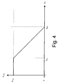
- the heating power of the PTC heating elements during operation on a Maximum value set, as long as the detected supply air temperature is less than a first predetermined temperature is.
- the heating power then gradually or continuously lowered.
- This can be a Transition region between the maximum heating power range and a temperature range, in which no heating power is required to be realized. To this Way creates no unpleasant jump in temperature in the vehicle interior in the automatic shutdown of the heating power, but the heating power is shut down upon reaching the first threshold, preferably until reaching a second predetermined temperature of the incoming Air.
- the heating power of the electric auxiliary heater when it reaches a threshold temperature between 10 ° C and 25 ° C, most preferably between 18 ° C and 22 ° C reduced.
- a temperature range between 50 ° C and 90 ° C preferably between 75 ° C and 85 ° C of the incoming air reaches the heating power of the auxiliary heater is zero.
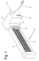
- Booster heater 100 shown in a perspective view of a possible embodiment of the invention Booster heater 100 shown.
- the additional heater has a Heating register 110 from radiator elements and arranged in these PTC heating elements.
- the heater 110 is in a metal or plastic housing 120 arranged.
- the components are under a clamping pressure held to increase the efficiency of the PTC heating elements, through an improvement of the thermal and electrical contact.
- a control circuit In a laterally adjacent to the housing 120 of the heating register 110 housing portion 130, a control circuit is arranged.
- the control circuit determines when power is supplied to the PTC heating elements and what amounts of electricity.
- the control circuit has a positive terminal 140 and a Ground connection 150.
- the control circuit supplies power to the PTC heating elements.
- power semiconductor devices To the circuit of the power, power semiconductor devices are used. The waste heat of this Semiconductor power devices become air vents protruding into the airflow the cooling elements 180 fed to the air flow to be heated.
- the temperature sensor 170 is arranged so that it can be heated in the air flow Air is lying. Thereby, the temperature sensor 170, the temperature of the incoming Detect air and pass it on to the control circuit.
- the temperature sensor 170 is also shown in a different way than in Fig. 1 on the housing mountable, as long as it is ensured that it by the heating power of the heating register is not affected.
- the control circuit is preferably an external one Signal supplied, which is available in the vehicle electrical system electrical power indicates. This allows the control circuit to automatically adjust how much power it takes over the connections 140, 150 from the electrical system. An overload of the On-board network and a discharge of the vehicle battery can thus effectively prevented become.
- the structure of the heating register 110 is shown schematically in FIG. Between the radiator elements 200 PTC heating elements 210 are arranged. The two shown PTC heating elements 210 are with the radiator elements 200 in heat-conducting Connection. Via the radiator elements 200, that of the PTC heating element 210 generated heat to the flowing through the radiator elements 200 Air discharged.
- contact plates 220, 230, 240th are contact plates 220, 230, 240th arranged. Via these contact plates 210 power is supplied to the PTC heating element. This does not require all contact plates 220, 230, 240 even with a Be provided power connection. 2, two contact sheets 230, 240 are shown, which are led out of the heating surface to the right. The two led out Contact sheets 230, 240 may be connected to opposite current potential become.
- the contact plate 220 is preferably over the intermediate electrically conductive trained radiator 200 also to the potential the contact plate 230 laid. In this way, a small number is sufficient from power supply connections to the PTC heating elements.
- the structure shown in Fig. 2 only schematically represents the arrangement principle.
- the structure is held under a clamping pressure, so that a particular good thermal and electrical transition between the PTC heating element 210 and the contact plates 220, 230 and 240 consists.
- the temperature sensor 170 is integrated in the heating device.
- the temperature sensor 170 measures the temperature ⁇ In , the air flowing into the auxiliary electric heater.
- the air flowing into the additional heating air has the temperature ⁇ in the emerging from the water heat exchanger air.
- the DF signal is a measure of the Utilization of the motor vehicle generator, the utilization of the duty cycle the DF signal is specified.
- the DF signal is often in a range of 0% to 100% stated.
- the indication of 0% means almost no excitement and thus no Power output to the electrical system.
- 100% means maximum excitement and thus maximum power output to the electrical system with unchanged vehicle electrical system voltage (e.g., 14.5V).
- the power extraction is set from the electrical system, that an excitation, ie generator utilization, of 95% is achieved.
- the power consumption of the additional electric heater be adapted to the load of the motor vehicle generator.
- the DF signal is available in every motor vehicle and can be tapped directly on the vehicle generator.
- the vehicle electrical system voltage continuously monitored by the additional heater is always adjusted so that the vehicle electrical system voltage does not fall below a predetermined minimum value, for example one Value of the order of 14V.
- the generator controller i. the regulator of the alternator of the motor vehicle stops by changing the generator excitation the vehicle electrical system voltage stable on one constant value. As soon as the maximum excitation is reached, the vehicle electrical system voltage begins However, they do not descend, as they are no longer affected by an increase in arousal is compensable. The vehicle electrical system voltage drops in a further increase in Power extraction down to a value of about 12 V to 12.5 V from. At this Voltage becomes additional electrical power of the battery of the motor vehicle taken.
- the vehicle electrical system voltage actually already at a utilization level of the generator starts to drop slightly in the range of about 85%, can the power extraction of the additional heating safely to a predetermined Adjust the degree of utilization of the generator, preferably the degree of utilization is in the range of 90% to 100%, most preferably on the order of magnitude of 95%.
- the generator voltage may vary based on manufacturer and vehicle type the outside temperature can be changed. In particular, the vehicle voltage raised at low temperatures. The voltage value will be the same accordingly of the vehicle electrical system, which corresponds to a certain capacity utilization and not may be exceeded, raised in the electric auxiliary heater. In general the voltage is in a range between 14.0 V and 14.5 V. varied. For newer batteries and vehicle types, the charging voltage can be temperature-dependent be set between about 14.0V and 15.5V. This is going through allows a modified chemical system of the battery.
- the additional electrical heating is switched on only when the engine is running, So then, when electric power is generated by the generator. This avoids that electrical power for heating the battery is removed.
- the control circuit of the heater observes the vehicle electrical system voltage of the motor vehicle.
- a starting process can be based on the electrical system voltage, among other things recognize that the vehicle electrical system voltage suddenly breaks down and then gradually back to baseline and above.
- the battery voltage is between 12.0 and 12.5 volts, breaks the vehicle electrical system voltage when starting the engine abruptly to a value in of the order of 6.0 volts. Subsequently, the vehicle electrical system voltage increases gradually back on.
- Another possibility for detecting the starting process via the vehicle electrical system voltage consists in the direct evaluation of the amount of voltage.
- switched off Motor gives the generator no power and the vehicle electrical system voltage corresponds the battery (discharge) voltage. This is typically in one area from 12.0 and 12.5 volts.
- the vehicle electrical system voltage increases on the battery charging voltage. This is typically in one area between 14.0 and 14.5 volts.
- the additional electric heater is activated when, when the ignition is switched on, ie when the engine is started, the measured temperature ⁇ In is below a preset value ⁇ V.
- a preset value ⁇ V is, for example, on the order of 10 ° C.
- the measured temperature ⁇ In deviates from the outside temperature ⁇ A when the engine still has residual heat, for example, because it has been switched off only a short time ago.
- the temperature sensor 170 does not detect the outside temperature but the ambient air warmed by the residual heat of the heat exchanger.
- the time that has elapsed since the engine was last switched off is recorded. If the detected time T out does not exceed a predetermined minimum value T Min , then the additional heating is not switched on.
- T Min Only when the predetermined minimum value T Min is exceeded, the additional heating is switched on at the next engine start - provided that the required temperature switch-on criterion is met.
- Typical numerical values for the minimum time value T min are in the range of several hours.
- the detected value T may be made of ⁇ also to modify the temperature threshold value V be used.
- the temperature threshold ⁇ V supplied to the comparing means changes depending on the elapsed time Toff.
- the power supply to the PTC heating elements remains disabled. Also independent of the temperature switch-on criterion, the additional electric heater is not activated.
- the temperature threshold ⁇ V ⁇ from a value V1 gradually up to the stored lower temperature threshold ⁇ V0 lowered.
- the temperature threshold ⁇ V changes to the value ⁇ V0 .
- the minimum temperature threshold ⁇ V0 is used.
- the threshold T Min2 is set so that the motor is fully cooled from this point onwards.
- the control circuit supplies power to the PTC heating elements, the Motor vehicle interior supplied air heated accordingly.
- the auxiliary heater works with the maximum possible depending on the electrical system Heating capacity.
- the individual room temperature regulation takes place via a Damp control for mixing warm and cold air.
- the additional heating system is activated switched off, depending on the measured temperature the air flowing into the auxiliary heater. With the shutdown is in the Interior air flowing but suddenly a large amount of heating energy withdrawn. This temperature jump is also in the interior of the temperature jump the air flowing into the vehicle interior noticeable.
- the heating power the electric auxiliary heater depending on, for example, the cooling water temperature off.
- the reduced Heating power of the additional heating gradually to zero.
- FIG. 5 A detailed implementation of an electric booster heater 100 is shown in FIG. 5 in FIG block diagram-like form reproduced.
- the electric auxiliary heater comprises a control circuit 510 and a heater 520.
- the housing of the heater 520 is in the circuit structure of FIG. 5 also associated with the temperature sensor 170, which is arranged on the side flowing to the heater side.
- the value detected by the temperature sensor 170 is passed to the control circuit 510 and fed via an analog / digital converter 533 to a computing unit 530.
- the computing unit 530 controls electronic switches 540.
- the electronic switches 540 which are preferably designed as power semiconductors, supply current from the terminal 140 to the heating elements 210.
- the control circuit 510 detects via the DF signal 180 available in the motor vehicle electrical power reserves.
- the DF signal is supplied via an interface device 535 of the arithmetic unit 530.
- control circuit 510 includes a voltage regulator 537 which controls the Operating voltage for the computing unit 530 provides, usually in height of 5 V.
- the temperature sensor 170 is preferably at the electric auxiliary heater mounted that he did not by heating the heating elements of the auxiliary heater being affected. In addition to the position shown in Fig. 1 for the temperature sensor 170 a variety of other positions is possible.
- the control circuit 510 is preferably in a housing with the heater register 520 integrated.
- the control circuit at one of the end faces of the heating register be attached; however, it is also an attachable or separate, but adjacent arrangement of the heating register 520 and the control circuit 510 possible.
- the present invention relates to an electric heater, in particular as additional heating for a motor vehicle, and a control circuit for an electric heater, which is a substantially self-sufficient operation allow the additional heating.
- the heating power control is via a in the auxiliary heater integrated temperature sensor and in advance in the control circuit stored limits.
Landscapes
- Engineering & Computer Science (AREA)
- Physics & Mathematics (AREA)
- Thermal Sciences (AREA)
- Mechanical Engineering (AREA)
- Chemical & Material Sciences (AREA)
- Combustion & Propulsion (AREA)
- General Engineering & Computer Science (AREA)
- Air-Conditioning For Vehicles (AREA)
Priority Applications (5)
| Application Number | Priority Date | Filing Date | Title |
|---|---|---|---|
| EP03021405A EP1516761A1 (fr) | 2003-09-22 | 2003-09-22 | Dispositif de chauffage électrique avec un capteur de température |
| CNB200410029429XA CN100393540C (zh) | 2003-09-22 | 2004-03-17 | 具有集成的温度传感器的电加热装置 |
| US10/937,729 US20050061798A1 (en) | 2003-09-22 | 2004-09-09 | Electric heating apparatus with integrated temperatrure sensor |
| KR1020040075529A KR100701377B1 (ko) | 2003-09-22 | 2004-09-21 | 온도 센서가 통합된 전기 가열 장치 |
| JP2004273567A JP2005096756A (ja) | 2003-09-22 | 2004-09-21 | 温度センサが組み込まれた電気加熱装置 |
Applications Claiming Priority (1)
| Application Number | Priority Date | Filing Date | Title |
|---|---|---|---|
| EP03021405A EP1516761A1 (fr) | 2003-09-22 | 2003-09-22 | Dispositif de chauffage électrique avec un capteur de température |
Publications (1)
| Publication Number | Publication Date |
|---|---|
| EP1516761A1 true EP1516761A1 (fr) | 2005-03-23 |
Family
ID=34178473
Family Applications (1)
| Application Number | Title | Priority Date | Filing Date |
|---|---|---|---|
| EP03021405A Withdrawn EP1516761A1 (fr) | 2003-09-22 | 2003-09-22 | Dispositif de chauffage électrique avec un capteur de température |
Country Status (5)
| Country | Link |
|---|---|
| US (1) | US20050061798A1 (fr) |
| EP (1) | EP1516761A1 (fr) |
| JP (1) | JP2005096756A (fr) |
| KR (1) | KR100701377B1 (fr) |
| CN (1) | CN100393540C (fr) |
Cited By (6)
| Publication number | Priority date | Publication date | Assignee | Title |
|---|---|---|---|---|
| EP1928214A1 (fr) * | 2006-11-30 | 2008-06-04 | Catem GmbH & Co.KG | Dispositif de chauffage électrique |
| EP2653330A1 (fr) * | 2012-04-21 | 2013-10-23 | Volkswagen Aktiengesellschaft | Dispositif de chauffage auxiliaire et dispositif de climatisation pour un véhicule automobile |
| US8660747B2 (en) | 2008-01-24 | 2014-02-25 | Eberspacher Catem Gmbh & Co. Kg | Electrical auxiliary heating unit for a motor vehicle |
| EP2732995A1 (fr) | 2012-11-15 | 2014-05-21 | Eberspächer catem GmbH & Co. KG | Chauffage électrique pour véhicule automobile |
| EP2772375A1 (fr) | 2013-02-27 | 2014-09-03 | Eberspächer catem GmbH & Co. KG | Dispositif de chauffage électrique pour un véhicule automobile |
| CN111449299A (zh) * | 2014-08-22 | 2020-07-28 | 富特姆4有限公司 | 用于控制加热元件的方法、系统和装置 |
Families Citing this family (34)
| Publication number | Priority date | Publication date | Assignee | Title |
|---|---|---|---|---|
| EP1527916A1 (fr) * | 2003-10-27 | 2005-05-04 | Behr GmbH & Co. KG | Système de chauffage pour véhicule avec source de chaleur auxiliaire |
| DE502005005264D1 (de) * | 2005-07-26 | 2008-10-16 | Behr France Rouffach Sas | Heizungsanordnung mit PCT-Element, insbesondere für ein Kraftfahrzeug |
| JP4981386B2 (ja) * | 2006-08-30 | 2012-07-18 | 三菱重工業株式会社 | 熱媒体加熱装置およびそれを用いた車両用空調装置 |
| EP2082920B1 (fr) * | 2008-01-24 | 2012-04-11 | Eberspächer catem GmbH & Co. KG | Chauffage électrique d'appoint pour véhicule automobile |
| EP2371588B1 (fr) * | 2010-03-26 | 2012-10-10 | Eberspächer catem GmbH & Co. KG | Dispositif de chauffage électrique |
| JP5535740B2 (ja) * | 2010-04-14 | 2014-07-02 | 三菱重工業株式会社 | 熱媒体加熱装置およびそれを用いた車両用空調装置 |
| CN101927677B (zh) * | 2010-08-17 | 2013-06-12 | 芜湖博耐尔汽车电气系统有限公司 | 一种汽车空调 |
| KR101659885B1 (ko) * | 2010-09-15 | 2016-09-26 | 한온시스템 주식회사 | 차량용 공조장치 및 그 제어방법 |
| CN102434950B (zh) * | 2011-09-15 | 2014-04-30 | 上海贝洱热系统有限公司 | 集成式防护格栅及新能源汽车空调器 |
| CN102512075B (zh) * | 2011-12-19 | 2014-04-09 | 江苏罗思韦尔电气有限公司 | 车载加热水杯 |
| DE102012112837B4 (de) * | 2012-12-21 | 2015-05-13 | Borgwarner Ludwigsburg Gmbh | Fahrzeugheizung und Verfahren zum Herstellen einer Fahrzeugheizung |
| CN103974475A (zh) * | 2013-02-06 | 2014-08-06 | 博格华纳贝鲁系统有限公司 | 陶瓷棒和在辅助或液体加热器中将其用作加热棒的应用 |
| EP2772820B1 (fr) | 2013-02-27 | 2015-04-08 | Eberspächer catem GmbH & Co. KG | Dispositif de chauffage électrique pour un véhicule automobile |
| FR3007229B1 (fr) * | 2013-06-17 | 2015-06-19 | Valeo Systemes Thermiques | Commande d'un circuit de chauffage electrique, notamment pour vehicule automobile |
| KR101987489B1 (ko) * | 2013-09-24 | 2019-06-10 | 현대자동차주식회사 | Cod 히터 |
| CN104596019A (zh) * | 2013-10-30 | 2015-05-06 | 北汽福田汽车股份有限公司 | 空调控制系统及空调控制方法 |
| DE102013227034A1 (de) * | 2013-12-20 | 2015-06-25 | Bayerische Motoren Werke Aktiengesellschaft | Thermomanagement für ein Elektro- oder Hybridfahrzeug sowie ein Verfahren zur Konditionierung des Innenraums eines solchen Kraftfahrzeugs |
| CN104354561B (zh) * | 2014-09-16 | 2017-09-12 | 奇瑞汽车股份有限公司 | 基于电动空调的ptc控制系统 |
| DE102016215549A1 (de) | 2016-08-18 | 2018-02-22 | Bayerische Motoren Werke Aktiengesellschaft | Elektrische Heizeinrichtung für Kraftfahrzeuge |
| CN106252789A (zh) * | 2016-09-13 | 2016-12-21 | 深圳市赛尔盈电子有限公司 | 一种新型电动汽车用ptc加热器及集成控制系统 |
| JP6889548B2 (ja) * | 2016-12-01 | 2021-06-18 | サンデン・オートモーティブクライメイトシステム株式会社 | 車両用空気調和装置 |
| FR3077703B1 (fr) * | 2018-02-08 | 2020-01-17 | Psa Automobiles Sa | Procede de controle de l’alimentation de moyens de chauffage electrique d’un systeme, en fonction de la puissance electrique disponible et des besoins. |
| FR3077702A1 (fr) * | 2018-02-08 | 2019-08-09 | Psa Automobiles Sa | Dispositif de controle de l’alimentation de moyens de chauffage electrique d’un systeme, en fonction de la puissance electrique disponible. |
| FR3077704B1 (fr) * | 2018-02-08 | 2022-09-09 | Psa Automobiles Sa | Procede de controle de l’alimentation de moyens de chauffage electrique d’un systeme, en fonction de la puissance electrique disponible, des besoins et d’une priorite. |
| DE102018210034A1 (de) * | 2018-06-20 | 2019-12-24 | Mahle International Gmbh | Verfahren zum digitalen Steuern einer Heizanordnung und die Heizanordnung |
| CN110185559B (zh) * | 2019-06-29 | 2020-09-29 | 潍柴动力股份有限公司 | 一种进气加热控制方法、装置及系统 |
| CN112741680B (zh) * | 2019-12-31 | 2023-02-03 | 杭州堃博生物科技有限公司 | 蒸汽消融设备及其消融准备控制方法与消融准备控制器 |
| CN111563922B (zh) * | 2020-03-26 | 2023-09-26 | 北京迈格威科技有限公司 | 视觉定位方法、装置、电子设备及存储介质 |
| CN112060855B (zh) * | 2020-09-01 | 2022-04-08 | 珠海格力电器股份有限公司 | 冷链运输控制装置、制冷机组及运输工具 |
| CN112248754A (zh) * | 2020-10-30 | 2021-01-22 | 浙江飞碟汽车制造有限公司 | 一种纯电动车水暖ptc加热器控制系统及方法 |
| CN116135091B (zh) * | 2021-11-18 | 2025-07-25 | 珠海优特智厨科技有限公司 | 温度控制装置及方法 |
| CN114407615B (zh) * | 2022-02-23 | 2024-04-12 | 广汽埃安新能源汽车有限公司 | 一种外接加热器的控制方法及装置 |
| CN116105235A (zh) * | 2022-12-09 | 2023-05-12 | 青岛海尔空调器有限总公司 | 空调器室内机及空调器 |
| KR102839835B1 (ko) * | 2025-04-03 | 2025-07-29 | 주식회사 에이스디바이스 | 제어 로직 계층화를 적용한 전기자동차용 ptc 히터 통합 제어 모듈 |
Citations (6)
| Publication number | Priority date | Publication date | Assignee | Title |
|---|---|---|---|---|
| US5332958A (en) * | 1986-12-12 | 1994-07-26 | Sloan Jeffrey M | Battery disconnect device |
| US5547125A (en) * | 1995-08-01 | 1996-08-20 | Chrysler Corporation | Vehicle climate control system and operating method |
| DE19728589C1 (de) * | 1997-07-04 | 1998-11-05 | Audi Ag | Elektrische Zusatzheizung für Kraftfahrzeuge |
| US6072153A (en) * | 1997-12-25 | 2000-06-06 | Denso Corporation | Air conditioning apparatus having electric heating member integrated with heat exchanger |
| US6078024A (en) * | 1997-05-27 | 2000-06-20 | Denso Corporation | Air conditioning apparatus having electric heating member integrated with heating heat exchanger |
| US6118099A (en) * | 1998-11-12 | 2000-09-12 | Daimlerchrysler Corporation | Controller for heating in reversible air conditioning and heat pump HVAC system for electric vehicles |
Family Cites Families (26)
| Publication number | Priority date | Publication date | Assignee | Title |
|---|---|---|---|---|
| JPS56154308A (en) * | 1980-04-29 | 1981-11-28 | Nippon Soken Inc | Electric room heater for car |
| US4678982A (en) * | 1986-04-16 | 1987-07-07 | Offiler Stephen B | Supplemental automotive vehicular heater system and method of providing same |
| US4902956A (en) * | 1986-12-12 | 1990-02-20 | Sloan Jeffrey M | Safety device to prevent excessive battery drain |
| JPH0364108U (fr) * | 1989-10-30 | 1991-06-21 | ||
| JPH04260907A (ja) * | 1990-10-19 | 1992-09-16 | Tokyo Electric Co Ltd | 加熱回転体の温度制御装置 |
| JP3278677B2 (ja) * | 1991-02-08 | 2002-04-30 | 株式会社ゼクセルヴァレオクライメートコントロール | ヒートポンプ式空調装置 |
| US5280158A (en) * | 1992-05-01 | 1994-01-18 | Matava Stephen J | Controller for electric heaters for internal combustion engine |
| US5279459A (en) * | 1993-03-24 | 1994-01-18 | Ford Motor Company | Multiple temperature control system for an automotive vehicle |
| JPH0740218U (ja) * | 1993-12-28 | 1995-07-18 | 株式会社ユーシン | 自動車用簡易暖房装置 |
| JP3858373B2 (ja) * | 1997-09-17 | 2006-12-13 | 株式会社デンソー | 車両用空調装置 |
| JP3840781B2 (ja) * | 1997-05-27 | 2006-11-01 | 株式会社デンソー | 車両用空調装置 |
| JP3807072B2 (ja) * | 1998-02-09 | 2006-08-09 | 株式会社デンソー | 車両用空調装置 |
| JP3524373B2 (ja) * | 1998-03-17 | 2004-05-10 | 株式会社日立ユニシアオートモティブ | 空燃比センサのヒータ制御装置 |
| IL139676A (en) * | 1998-05-15 | 2005-12-18 | Vasu Tech Ltd | Multipoint digital temperatur controller |
| JP3982064B2 (ja) * | 1998-06-19 | 2007-09-26 | 株式会社デンソー | 車両用空調装置 |
| US6018151A (en) * | 1998-07-31 | 2000-01-25 | Hewlett-Packard Co. | Predictive fusing system for use in electrophotographic printers and copiers |
| DE19918906C2 (de) * | 1999-04-26 | 2003-07-17 | Valeo Klimasysteme Gmbh | PTC-Heizregister |
| DE19920061C1 (de) * | 1999-05-03 | 2000-11-16 | Daimler Chrysler Ag | Heizungs- oder Klimaanlage für eine Fahrgastzelle eines Kraftfahrzeugs |
| JP3824824B2 (ja) * | 1999-10-28 | 2006-09-20 | サンデン株式会社 | 車両用空調装置 |
| US6262400B1 (en) * | 2000-10-03 | 2001-07-17 | Delphi Technologies, Inc. | Control method for a resistance heater in a vehicle heating system |
| JP4453224B2 (ja) * | 2001-06-08 | 2010-04-21 | 株式会社デンソー | 車両用空調装置 |
| JP2003019964A (ja) * | 2001-07-09 | 2003-01-21 | Yazaki Corp | ステアリングヒーター |
| FR2838599B1 (fr) * | 2002-04-11 | 2004-08-06 | Valeo Climatisation | Dispositif de chauffage electrique, notamment pour appareil de chauffage et ou climatisation de vehicule |
| JP2003328821A (ja) * | 2002-05-15 | 2003-11-19 | Suzuki Motor Corp | 酸素センサの加熱制御装置 |
| EP1396361B1 (fr) * | 2002-09-05 | 2008-02-27 | Ford Global Technologies, LLC | Chauffage éléctrique pour un véhicule et son procédé de régulation |
| KR100686089B1 (ko) * | 2003-02-21 | 2007-02-23 | 엘지전자 주식회사 | 세탁기의 헹굼행정 제어방법 |
-
2003
- 2003-09-22 EP EP03021405A patent/EP1516761A1/fr not_active Withdrawn
-
2004
- 2004-03-17 CN CNB200410029429XA patent/CN100393540C/zh not_active Expired - Fee Related
- 2004-09-09 US US10/937,729 patent/US20050061798A1/en not_active Abandoned
- 2004-09-21 JP JP2004273567A patent/JP2005096756A/ja active Pending
- 2004-09-21 KR KR1020040075529A patent/KR100701377B1/ko not_active Expired - Fee Related
Patent Citations (6)
| Publication number | Priority date | Publication date | Assignee | Title |
|---|---|---|---|---|
| US5332958A (en) * | 1986-12-12 | 1994-07-26 | Sloan Jeffrey M | Battery disconnect device |
| US5547125A (en) * | 1995-08-01 | 1996-08-20 | Chrysler Corporation | Vehicle climate control system and operating method |
| US6078024A (en) * | 1997-05-27 | 2000-06-20 | Denso Corporation | Air conditioning apparatus having electric heating member integrated with heating heat exchanger |
| DE19728589C1 (de) * | 1997-07-04 | 1998-11-05 | Audi Ag | Elektrische Zusatzheizung für Kraftfahrzeuge |
| US6072153A (en) * | 1997-12-25 | 2000-06-06 | Denso Corporation | Air conditioning apparatus having electric heating member integrated with heat exchanger |
| US6118099A (en) * | 1998-11-12 | 2000-09-12 | Daimlerchrysler Corporation | Controller for heating in reversible air conditioning and heat pump HVAC system for electric vehicles |
Cited By (9)
| Publication number | Priority date | Publication date | Assignee | Title |
|---|---|---|---|---|
| EP1928214A1 (fr) * | 2006-11-30 | 2008-06-04 | Catem GmbH & Co.KG | Dispositif de chauffage électrique |
| US8660747B2 (en) | 2008-01-24 | 2014-02-25 | Eberspacher Catem Gmbh & Co. Kg | Electrical auxiliary heating unit for a motor vehicle |
| EP2082919B2 (fr) † | 2008-01-24 | 2018-08-15 | Eberspächer catem GmbH & Co. KG | Chauffage électrique d'appoint pour un véhicule automobile |
| EP2653330A1 (fr) * | 2012-04-21 | 2013-10-23 | Volkswagen Aktiengesellschaft | Dispositif de chauffage auxiliaire et dispositif de climatisation pour un véhicule automobile |
| EP2732995A1 (fr) | 2012-11-15 | 2014-05-21 | Eberspächer catem GmbH & Co. KG | Chauffage électrique pour véhicule automobile |
| EP2772375A1 (fr) | 2013-02-27 | 2014-09-03 | Eberspächer catem GmbH & Co. KG | Dispositif de chauffage électrique pour un véhicule automobile |
| CN111449299A (zh) * | 2014-08-22 | 2020-07-28 | 富特姆4有限公司 | 用于控制加热元件的方法、系统和装置 |
| US11864279B2 (en) | 2014-08-22 | 2024-01-02 | Fontem Ventures B.V. | Method, system and device for controlling a heating element |
| CN111449299B (zh) * | 2014-08-22 | 2024-02-13 | 富特姆投资有限公司 | 用于控制加热元件的方法、系统和装置 |
Also Published As
| Publication number | Publication date |
|---|---|
| US20050061798A1 (en) | 2005-03-24 |
| CN100393540C (zh) | 2008-06-11 |
| CN1600589A (zh) | 2005-03-30 |
| KR20050029706A (ko) | 2005-03-28 |
| JP2005096756A (ja) | 2005-04-14 |
| KR100701377B1 (ko) | 2007-03-28 |
Similar Documents
| Publication | Publication Date | Title |
|---|---|---|
| DE102005022204B4 (de) | Verfahren zum Aufheizen einer Batterie in einem Fahrzeug | |
| DE10334760B4 (de) | Kühlungssystem für Elektromotor und Kühlungssteuerungsverfahren | |
| KR100701377B1 (ko) | 온도 센서가 통합된 전기 가열 장치 | |
| EP1600337B1 (fr) | Coupe-circuit électronique pour batterie | |
| DE69925671T2 (de) | Regelsystem für totale Kühlung einer Brennkraftmaschine | |
| DE102016119144B4 (de) | Elektrisches fahrzeugsystem | |
| DE112004001059B4 (de) | Brennstoffzellenkühlsystem und Verfahren zum Steuern einer Zirkulation von Kühlflüssigkeit in der Brennstoffzelle | |
| EP2499690B1 (fr) | Procédé de thermorégulation et système de batterie | |
| DE19728814A1 (de) | Kühlanlage für einen Verbrennungsmotor eines Kraftfahrzeuges | |
| DE112018006195T5 (de) | Ladesteuervorrichtung, energiespeichervorrichtung und ladeverfahren | |
| EP3776713A1 (fr) | Dispositif d'équilibrage de température et ensemble de dispositif dans un système d'équilibrage de température | |
| EP1564862A1 (fr) | Réseau de bord d'un véhicule avec un transformateur de tension | |
| EP0559726B1 (fr) | Procede et dispositif de determination de la sollicitation et/ou de la resistance a la sollicitation de composants ou de groupes de composants a reglage electronique | |
| EP2179484B1 (fr) | Procédé et dispositif permettant de charger un accumulateur d'énergie | |
| EP0991537B1 (fr) | Chauffage electrique d'appoint pour vehicules | |
| EP1308610B1 (fr) | Procédé et dispositif pour commander un système de refroidissement d'un moteur à combustion interne | |
| DE19903082C2 (de) | Batteriesystem und Verfahren zum Betreiben eines Batteriesystems | |
| DE102007033429A1 (de) | Vorrichtung und Verfahren zum Aufwärmen einer Brennstoffzelle in einer Startphase | |
| EP1410479B1 (fr) | Procede et dispositif de commande de la recharge d'une batterie de vehicule automobile | |
| DE102022111447A1 (de) | Pulswechselrichter sowie Antriebsstrang und Verfahren zur Erwärmung eines Kühlmittels | |
| DE3822899A1 (de) | Verfahren zum betreiben eines heizgeraets und heizgeraet | |
| WO2009010113A1 (fr) | Dispositif et procédé permettant la montée en température d'une pile à combustible au cours d'une phase de démarrage | |
| WO2005078891A1 (fr) | Reseau de bord de vehicule automobile a conservation du courant d'alternateur separee de la batterie | |
| EP1564077A1 (fr) | Distributeur de courant éléctronique pour un réseau de bord d'un véhicule automobile | |
| DE102014111517A1 (de) | Verfahren zum Betrieb eines Fahrzeugs und Fahrzeug |
Legal Events
| Date | Code | Title | Description |
|---|---|---|---|
| PUAI | Public reference made under article 153(3) epc to a published international application that has entered the european phase |
Free format text: ORIGINAL CODE: 0009012 |
|
| 17P | Request for examination filed |
Effective date: 20040820 |
|
| AK | Designated contracting states |
Kind code of ref document: A1 Designated state(s): AT BE BG CH CY CZ DE DK EE ES FI FR GB GR HU IE IT LI LU MC NL PT RO SE SI SK TR |
|
| AX | Request for extension of the european patent |
Extension state: AL LT LV MK |
|
| 17Q | First examination report despatched |
Effective date: 20050406 |
|
| AKX | Designation fees paid |
Designated state(s): AT BE BG CH CY CZ DE DK EE ES FI FR GB GR HU IE IT LI LU MC NL PT RO SE SI SK TR |
|
| STAA | Information on the status of an ep patent application or granted ep patent |
Free format text: STATUS: THE APPLICATION IS DEEMED TO BE WITHDRAWN |
|
| 18D | Application deemed to be withdrawn |
Effective date: 20061010 |