EP2772375A1 - Dispositif de chauffage électrique pour un véhicule automobile - Google Patents
Dispositif de chauffage électrique pour un véhicule automobile Download PDFInfo
- Publication number
- EP2772375A1 EP2772375A1 EP13156989.9A EP13156989A EP2772375A1 EP 2772375 A1 EP2772375 A1 EP 2772375A1 EP 13156989 A EP13156989 A EP 13156989A EP 2772375 A1 EP2772375 A1 EP 2772375A1
- Authority
- EP
- European Patent Office
- Prior art keywords
- heating
- temperature
- heat
- temperature sensor
- ptc
- Prior art date
- Legal status (The legal status is an assumption and is not a legal conclusion. Google has not performed a legal analysis and makes no representation as to the accuracy of the status listed.)
- Granted
Links
Images


Classifications
-
- B—PERFORMING OPERATIONS; TRANSPORTING
- B60—VEHICLES IN GENERAL
- B60H—ARRANGEMENTS OF HEATING, COOLING, VENTILATING OR OTHER AIR-TREATING DEVICES SPECIALLY ADAPTED FOR PASSENGER OR GOODS SPACES OF VEHICLES
- B60H1/00—Heating, cooling or ventilating devices
- B60H1/00357—Air-conditioning arrangements specially adapted for particular vehicles
- B60H1/00385—Air-conditioning arrangements specially adapted for particular vehicles for vehicles having an electrical drive, e.g. hybrid or fuel cell
-
- B—PERFORMING OPERATIONS; TRANSPORTING
- B60—VEHICLES IN GENERAL
- B60H—ARRANGEMENTS OF HEATING, COOLING, VENTILATING OR OTHER AIR-TREATING DEVICES SPECIALLY ADAPTED FOR PASSENGER OR GOODS SPACES OF VEHICLES
- B60H1/00—Heating, cooling or ventilating devices
- B60H1/22—Heating, cooling or ventilating devices the heat source being other than the propulsion plant
- B60H1/2215—Heating, cooling or ventilating devices the heat source being other than the propulsion plant the heat being derived from electric heaters
- B60H1/2218—Heating, cooling or ventilating devices the heat source being other than the propulsion plant the heat being derived from electric heaters controlling the operation of electric heaters
-
- F—MECHANICAL ENGINEERING; LIGHTING; HEATING; WEAPONS; BLASTING
- F24—HEATING; RANGES; VENTILATING
- F24H—FLUID HEATERS, e.g. WATER OR AIR HEATERS, HAVING HEAT-GENERATING MEANS, e.g. HEAT PUMPS, IN GENERAL
- F24H3/00—Air heaters
- F24H3/02—Air heaters with forced circulation
- F24H3/04—Air heaters with forced circulation the air being in direct contact with the heating medium, e.g. electric heating element
- F24H3/0405—Air heaters with forced circulation the air being in direct contact with the heating medium, e.g. electric heating element using electric energy supply, e.g. the heating medium being a resistive element; Heating by direct contact, i.e. with resistive elements, electrodes and fins being bonded together without additional element in-between
- F24H3/0429—For vehicles
-
- F—MECHANICAL ENGINEERING; LIGHTING; HEATING; WEAPONS; BLASTING
- F24—HEATING; RANGES; VENTILATING
- F24H—FLUID HEATERS, e.g. WATER OR AIR HEATERS, HAVING HEAT-GENERATING MEANS, e.g. HEAT PUMPS, IN GENERAL
- F24H3/00—Air heaters
- F24H3/02—Air heaters with forced circulation
- F24H3/04—Air heaters with forced circulation the air being in direct contact with the heating medium, e.g. electric heating element
- F24H3/0405—Air heaters with forced circulation the air being in direct contact with the heating medium, e.g. electric heating element using electric energy supply, e.g. the heating medium being a resistive element; Heating by direct contact, i.e. with resistive elements, electrodes and fins being bonded together without additional element in-between
- F24H3/0429—For vehicles
- F24H3/0435—Structures comprising heat spreading elements in the form of fins
-
- F—MECHANICAL ENGINEERING; LIGHTING; HEATING; WEAPONS; BLASTING
- F24—HEATING; RANGES; VENTILATING
- F24H—FLUID HEATERS, e.g. WATER OR AIR HEATERS, HAVING HEAT-GENERATING MEANS, e.g. HEAT PUMPS, IN GENERAL
- F24H3/00—Air heaters
- F24H3/02—Air heaters with forced circulation
- F24H3/04—Air heaters with forced circulation the air being in direct contact with the heating medium, e.g. electric heating element
- F24H3/0405—Air heaters with forced circulation the air being in direct contact with the heating medium, e.g. electric heating element using electric energy supply, e.g. the heating medium being a resistive element; Heating by direct contact, i.e. with resistive elements, electrodes and fins being bonded together without additional element in-between
- F24H3/0429—For vehicles
- F24H3/0441—Interfaces between the electrodes of a resistive heating element and the power supply means
- F24H3/0447—Forms of the electrode terminals, e.g. tongues or clips
-
- G—PHYSICS
- G05—CONTROLLING; REGULATING
- G05D—SYSTEMS FOR CONTROLLING OR REGULATING NON-ELECTRIC VARIABLES
- G05D23/00—Control of temperature
- G05D23/19—Control of temperature characterised by the use of electric means
- G05D23/1917—Control of temperature characterised by the use of electric means using digital means
-
- G—PHYSICS
- G05—CONTROLLING; REGULATING
- G05D—SYSTEMS FOR CONTROLLING OR REGULATING NON-ELECTRIC VARIABLES
- G05D23/00—Control of temperature
- G05D23/19—Control of temperature characterised by the use of electric means
- G05D23/20—Control of temperature characterised by the use of electric means with sensing elements having variation of electric or magnetic properties with change of temperature
-
- H—ELECTRICITY
- H05—ELECTRIC TECHNIQUES NOT OTHERWISE PROVIDED FOR
- H05B—ELECTRIC HEATING; ELECTRIC LIGHT SOURCES NOT OTHERWISE PROVIDED FOR; CIRCUIT ARRANGEMENTS FOR ELECTRIC LIGHT SOURCES, IN GENERAL
- H05B3/00—Ohmic-resistance heating
- H05B3/40—Heating elements having the shape of rods or tubes
- H05B3/42—Heating elements having the shape of rods or tubes non-flexible
-
- B—PERFORMING OPERATIONS; TRANSPORTING
- B60—VEHICLES IN GENERAL
- B60H—ARRANGEMENTS OF HEATING, COOLING, VENTILATING OR OTHER AIR-TREATING DEVICES SPECIALLY ADAPTED FOR PASSENGER OR GOODS SPACES OF VEHICLES
- B60H1/00—Heating, cooling or ventilating devices
- B60H1/22—Heating, cooling or ventilating devices the heat source being other than the propulsion plant
- B60H2001/2228—Heating, cooling or ventilating devices the heat source being other than the propulsion plant controlling the operation of heaters
- B60H2001/2231—Heating, cooling or ventilating devices the heat source being other than the propulsion plant controlling the operation of heaters for proper or safe operation of the heater
-
- B—PERFORMING OPERATIONS; TRANSPORTING
- B60—VEHICLES IN GENERAL
- B60H—ARRANGEMENTS OF HEATING, COOLING, VENTILATING OR OTHER AIR-TREATING DEVICES SPECIALLY ADAPTED FOR PASSENGER OR GOODS SPACES OF VEHICLES
- B60H1/00—Heating, cooling or ventilating devices
- B60H1/22—Heating, cooling or ventilating devices the heat source being other than the propulsion plant
- B60H2001/2246—Heating, cooling or ventilating devices the heat source being other than the propulsion plant obtaining information from a variable, e.g. by means of a sensor
- B60H2001/2256—Heating, cooling or ventilating devices the heat source being other than the propulsion plant obtaining information from a variable, e.g. by means of a sensor related to the operation of the heater itself, e.g. flame detection or overheating
-
- B—PERFORMING OPERATIONS; TRANSPORTING
- B60—VEHICLES IN GENERAL
- B60H—ARRANGEMENTS OF HEATING, COOLING, VENTILATING OR OTHER AIR-TREATING DEVICES SPECIALLY ADAPTED FOR PASSENGER OR GOODS SPACES OF VEHICLES
- B60H1/00—Heating, cooling or ventilating devices
- B60H1/22—Heating, cooling or ventilating devices the heat source being other than the propulsion plant
- B60H2001/2259—Heating, cooling or ventilating devices the heat source being other than the propulsion plant output of a control signal
- B60H2001/2265—Heating, cooling or ventilating devices the heat source being other than the propulsion plant output of a control signal related to the quantity of heat produced by the heater
-
- F—MECHANICAL ENGINEERING; LIGHTING; HEATING; WEAPONS; BLASTING
- F24—HEATING; RANGES; VENTILATING
- F24D—DOMESTIC- OR SPACE-HEATING SYSTEMS, e.g. CENTRAL HEATING SYSTEMS; DOMESTIC HOT-WATER SUPPLY SYSTEMS; ELEMENTS OR COMPONENTS THEREFOR
- F24D2220/00—Components of central heating installations excluding heat sources
- F24D2220/04—Sensors
- F24D2220/042—Temperature sensors
-
- H—ELECTRICITY
- H05—ELECTRIC TECHNIQUES NOT OTHERWISE PROVIDED FOR
- H05B—ELECTRIC HEATING; ELECTRIC LIGHT SOURCES NOT OTHERWISE PROVIDED FOR; CIRCUIT ARRANGEMENTS FOR ELECTRIC LIGHT SOURCES, IN GENERAL
- H05B2203/00—Aspects relating to Ohmic resistive heating covered by group H05B3/00
- H05B2203/02—Heaters using heating elements having a positive temperature coefficient
-
- H—ELECTRICITY
- H05—ELECTRIC TECHNIQUES NOT OTHERWISE PROVIDED FOR
- H05B—ELECTRIC HEATING; ELECTRIC LIGHT SOURCES NOT OTHERWISE PROVIDED FOR; CIRCUIT ARRANGEMENTS FOR ELECTRIC LIGHT SOURCES, IN GENERAL
- H05B2203/00—Aspects relating to Ohmic resistive heating covered by group H05B3/00
- H05B2203/022—Heaters specially adapted for heating gaseous material
- H05B2203/023—Heaters of the type used for electrically heating the air blown in a vehicle compartment by the vehicle heating system
Definitions
- the present invention relates to an electric heating device for a motor vehicle.
- the present invention relates to an electric heater with PTC heating elements for heating an air flow, which is equipped with an overheat protection device.
- electric heaters in the motor vehicle are used, for example, as additional heaters to supplement the heating of the motor vehicle interior and other components, which is primarily due to the heat of the engine, or to allow, for example, a heating at standstill of the vehicle ,
- PTC positive temperature coefficient
- electric heaters in vehicles with electric or hybrid drive in which the drive unit of the motor vehicle emits no or no sufficient waste heat for heating or air conditioning of the vehicle.
- air heaters are particularly suitable because they can achieve high efficiency and can be made compact by direct heating of the air without the interposition of a water heat exchanger.
- a heater for electric or hybrid vehicles is suitable, in addition to the supply of the interior of the motor vehicle with the required heat and the heat for the running processes in individual parts of the system Motor vehicle required or at least to provide this promotional heat, such as for preheating the vehicle battery.
- Electric heaters for an electric or hybrid vehicle must therefore be more powerful dimensioned than PTC heaters, which are used for example as additional heater in a conventional motor vehicle, and therefore have a number of special features.
- the heaters used in electric and hybrid vehicles are for high voltage automotive (above 60 volts, preferably several hundred volts, up to 500 volts, typically between 280 volts and 430 volts (eg, 300 volts or 380 volts). ), since the vehicle batteries used provide such a vehicle electrical system voltage.
- the heating power of such high-voltage heaters is on the order of 3 to 6 kW (kilowatts), compared to an order of magnitude of 1 to 1.7 kW (eg 1.2 kW) for 12 volt auxiliary heaters for motor vehicles.
- such a high-voltage heater contains substantially more PTC heating elements than a conventional electrical auxiliary heater, preferably more than 40, more preferably between 50 and 100, for example about 60 PTC heating elements compared to 10 to 20 in the conventional motor vehicle.
- the power can be increased by increasing the heater surface contacted by the flowing air.
- the process of heat transfer from the heater surface to the airflow is additionally assisted by radiant heat emitted by the heater surface.
- An enlargement of the heater surface reaches its limits when used in a motor vehicle because the size of the installation space is predefined when installed in a heating / air conditioning unit.
- the transmitted power can also be increased by increasing the surface temperature of the heater. Since a larger temperature gradient occurs between the heater surface and the flowing air, more heat can be transferred in the same time than at a lower surface temperature.
- the second possibility of increasing the power transmission to the air to be heated is particularly suitable for high-voltage heaters for vehicles with electric drive (electric or hybrid vehicles).
- special PTC heating elements are used, which can reach higher surface temperatures during operation than the heating elements used in conventional PTC heaters.
- these PTC heating elements have a different resistance or power characteristic (shifted toward higher temperatures), and thus automatically adjust only at higher temperatures.
- the surface temperature of the PTC heating element increases to the maximum PTC surface temperature.
- the electrical power is reduced to a value that only corresponds to a fraction of the maximum possible power.
- a corresponding fault can also occur if, when controlling an electric heater, the air supply is significantly reduced or interrupted, without the amount of heat to be generated (predetermined power) is reduced accordingly. Such a situation can occur in case of failure within an automatic heating control or even with manual adjustment of a heating in consequence of incorrect operation.
- the temperature dependency of the electric power P el converted into heat by the PTC element is in Fig. 1 above the surface temperature of the PTC element.
- a current consumption (operating point) in the PTC element as a function of the ambient temperature, ie the temperature of the medium to be heated (air) and the heat conduction from the PTC element to be heated medium.
- Such an operating point is with the operating point A 1 at the temperature T 1 in Fig. 1 shown.
- the PTC element heats up due to a disturbance in the air flow, the amount of heat converted in the PTC element can no longer be dissipated.
- the PTC element then assumes a higher temperature. Its operating point on the characteristic shifts further down, as in Fig. 1 indicated with the new operating point A 2 at the temperature T 2 . In this case, the power consumption is significantly reduced and the PTC heating element can reach the predetermined by the doping maximum temperature T max .
- PTC elements which only regulate at significantly higher temperatures, but also allow higher surface temperatures during normal operation.
- the maximum possible surface temperature of the PTC heating elements themselves is now in a range of at least 180 ° C. Depending on the embodiment, maximum surface temperatures in the range of 200 ° C are possible.
- Such heating elements also allow a higher operating temperature of the heat radiating surface of the heater, such as radiators, which in turn, as described above, in view of the available in the motor vehicle limited installation space advantageous effect on the heat output.
- the self-regulating mechanism described above as overheating protection for vehicle safety is basically suitable, but not for plastic components in the immediate vicinity of the heater, as damage can occur when these PTC elements self-adjust.
- the maximum possible surface temperatures of the PTC elements due to the characteristic are achieved when the air flow fails (or at least the flow velocity drops significantly - low air flow rate).
- the flowing air ensures that sufficient heat is dissipated and the surface temperature of the PTC heating elements always remains below the maximum possible value.
- the maximum temperature near the heater is in the range of about 130 ° C with the fan off.
- it is at least about 30 to 60 degrees, z. B. 50 degrees, higher.
- the heating / air conditioning unit (HVAC - Heating-Ventilation-Air-Conditioning) is usually designed for a maximum operating temperature up to 130 ° C.
- HVAC Heating-Ventilation-Air-Conditioning
- the HVAC itself does not have its own protection against overheating. If, however, the surface temperature of the heating elements reaches 180 ° C or more in the event of a fault, then unacceptably high temperatures also quickly develop in the surrounding area in the HVAC. A low or precipitating airflow therefore leads to overheating that must be avoided. This occurs especially in the case of fan failure / fan failure, but may be the case even if - e.g. due to damage or incorrect operation - due to incorrect position of the air control flaps, the air is prevented from flowing and an air accumulation occurs.
- thermosensors are arranged so that it lies in the air flow of the air to be heated and detects the temperature of the incoming air and passes it on to the control circuit of the heater.
- the risk for the heating / air conditioning unit not only from the (heated) air, but in particular from the radiant heat of the PTC heating elements / heater surface.
- a measurement of a temperature of the air flow through the use of a temperature sensor in the air stream is therefore not suitable in the present case, at least for the defense against damage to environmental components.
- the measured temperature, when measured in the air flow, is strongly influenced by external factors such as air temperature and flow velocity, so that it does not allow unambiguous conclusions about the PTC surface temperature.
- an electric heater for a motor vehicle for heating an airflow comprises a heating block with at least one PTC heating element and at least one radiator element for heat radiation which is in heat-conducting contact with the PTC heating element.
- the heating device further comprises a housing with a frame which receives the heating block and a control device for adjusting the heating power of the at least one PTC heating element.
- the heating device comprises a temperature sensor which is connected to the control device and a heat-conducting element which conducts heat from the heating block to the temperature sensor.
- a method of manufacturing an electric heater for a motor vehicle for heating an airflow comprising a housing.
- the housing forms a frame in which a heating block is accommodated with at least one PTC heating element, and a separate control housing with a control device for adjusting the heating power of the at least one PTC heating element and a partition wall between the control device and heating block.
- the heating device comprises a temperature sensor which is connected to the control device.
- the method is characterized in that a plug connection is produced during the joining of the housing between a heat-conducting element arranged inside the frame and a receiving device for the temperature sensor provided in the dividing wall.
- the use of the heat-conducting element makes it possible, on the one hand, to arrange the temperature sensor outside the heating block and protected from external influences, in particular from the air flow.
- it leads to a good correlation between a temperature directly detected by the temperature sensor and a surface temperature of the heater, whereby the temperature of the surface of the heating elements can be indirectly measured. Consequently, it can be shed light on the intensity with which heat radiation takes place. As a result, an inadmissible heating can be detected in time, and the heating power can be reduced accordingly.
- Indirect determination of the surface temperature of the heating element means that the temperature detected by the sensor is, to a good approximation, a clear indicator of the surface temperature of the heating element.
- the PTC heating elements are designed so that they can reach a maximum surface temperature of 180 ° C or more.
- PTC heating elements must be used which can reach such surface temperatures in order to be able to transfer the high heat outputs required for vehicles with electric drive into the air despite limited installation space.
- the solution according to the invention is particularly advantageous when using such PTC heating elements.
- the PTC heating elements are designed for an operating voltage in automotive high voltage range. Such a design of the heating elements corresponds to the preferably provided use in vehicles with electric drive.
- the temperature sensor is arranged outside the air flow. This avoids that the good correlation between the detected temperature and the surface temperature of the heating element is disturbed or distorted by the influence of the air flow due to the known properties of theticianleitelements.
- the temperature sensor detects a temperature which is well correlated by heat conduction with a PTC surface temperature. It thus enables the indirect determination of the PTC surface temperature.
- An arrangement outside the air stream may e.g. be realized in that the temperature sensor is arranged outside of a receiving space formed by the frame for the heating block.
- the frame as a boundary of the receiving space at the same time represents a limitation of the area to be traversed by the air flow.
- the heat-conducting element contacts the radiator element.
- This can be carried out in particular in the form of a heating rib (corrugated fin).
- a plurality of heating fins may be arranged in a layer-like structure between a plurality of heating elements, wherein at least one of the Schurippenlagen is contacted by the heat-conducting element.
- the heat-conducting element directly contacts the PTC heating element.
- the heat-conducting element directly contacts the PTC heating element.
- the housing of the heating device forms, in addition to the frame for the heating block, a control housing in which the control device is arranged.
- Frame and control housing further preferably form a structural unit. This can be realized, for example, in that the control housing is plugged onto the frame carrying the heating block.
- the housing between the heating block and the control device forms a partition, which has a receiving device in which the temperature sensor embedded heat conductively.
- the partition is preferably made of plastic.
- the entire housing made of plastic, preferably made of particularly heat-resistant plastic.
- the receiving device is formed by a cup-shaped pin, which is encompassed by a terminal end of the heat-conducting element form fit.
- the heat-conducting element at the end opposite the heat source can have an integrally formed sleeve, which in turn encloses the pin in a form-fitting manner.
- the heat-conducting element is preferably also a heat-conducting sheet resting against the PTC heating element or the radiator element, which forms a contact sleeve at its connection end, which is plugged onto the journal.
- the temperature sensor may be embedded in the receiving device (in particular: a cavity in the interior of the pin) by means of a potting compound or thermal compound.
- the heating block comprises as radiator elements a plurality of parallel Grahamrippenlagen, between which the at least one PTC heating element is accommodated.
- the heat-conducting element is designed as a continuous layer of the heating block, that is, it has the same length as the Schurippenlagen or the PTC heating element.
- the electric heater comprises a fan for generating the air flow. Alternatively, generation of the airflow outside the range of the electric heater is possible.
- the heating device according to the invention comprises more than 40, more preferably between 50 and 100, for example 60 or about 60 PTC heating elements.
- control device is designed to reduce the heating power as a function of a temperature detected by the temperature sensor.
- control means includes monitoring means for monitoring whether the temperature detected by the temperature sensor exceeds a predetermined temperature value.
- the control device is further configured to reduce the heating power when the monitoring device determines that the temperature detected by the temperature sensor exceeds the predetermined temperature value.
- the predetermined temperature value is chosen so that its exceeding is an indication that the generation of the air flow is disturbed, and a safe and continuous heat dissipation can not be guaranteed.
- an impending heat accumulation must be counteracted by appropriate measures.
- a reasonable temperature threshold predetermined temperature value
- the reduction of the heating power to zero occurs when the measured temperature exceeds the threshold value. In this case, therefore, the heating power is switched off completely, and measures can be taken to the faulty heater detection or elimination.
- the heating power in case of overheating detected is reduced either stepwise or continuously (for example, linear).
- control device reduces the heating power only when the exceeding of the predetermined temperature value determined by the monitoring device lasts for longer than a predetermined period of time. This should be disregarded short-term fluctuations that can not cause injury.
- the heater shutdown or power reduction should independently regulate the heater to the maximum allowable temperature, but do not cause a permanent shutdown. Therefore, it is further preferably monitored by the monitoring device after reducing the heating power, whether the temperature detected by the temperature sensor falls below a second predetermined temperature value, wherein the second predetermined temperature value is lower than the predetermined temperature value, the exceeding of which leads to reducing the heating power. If the temperature at the heat exchanger is at least 50 degrees below the achievable PTC surface temperature of, for example, 200 ° C., a functioning heat dissipation can be assumed. Thus, a suitable second predetermined temperature value could be about 150 ° C, for example a value from the interval of 130 ° C or 140 ° C to 155 ° C.
- the control device is also preferably designed such that it increases the heating power again when the monitoring device determines that the temperature detected by the temperature sensor falls below the second predetermined temperature value. Upon reaching a second, lower threshold temperature so the heating power is switched on again. Also, the restarting of the heating power based on the second threshold temperature can be linked to a timer function, so that the on-hook occurs only when the second threshold temperature is exceeded during a predetermined period of time, to ignore short-term fluctuations.
- the heating block comprises a plurality of separately controllable heating stages (also referred to as heating circuits), each of which comprises at least one PTC heating element.
- a corresponding inventive heat conducting element and a temperature sensor according to the invention is provided separately for each heating stage.
- a temperature limitation can alternatively take place either in the form of a power reduction / deactivation of the affected heating circuit or else of the complete heating device.
- control can be performed such that initially only the power of the affected heating circuit, whose associated temperature sensor has detected the unacceptably high temperature, is reduced. If the temperature then does not drop back to permissible values within a predetermined time, then the heating power of adjacent or all heating circuits is subsequently reduced as well. For example, after a first predetermined time a power reduction of adjacent, and after a subsequent second predetermined time the power reduction of all heating circuits can be made, up to the complete shutdown of the heater.
- Such an embodiment provides the best possible protection since the installation situation and temperature stratifications within the HVAC can be better taken into account.
- the solution according to the invention is therefore particularly advantageous in this regard, since it allows the spatial separation between the tap of the temperature at the heater / radiator surface and the temperature sensor to detect and process the respective temperatures of the heating circuits separately.
- a centrally arranged heat conducting element with a single temperature sensor can be selected as.
- a centrally arranged common temperature sensor can accordingly be provided for every two heating stages.
- the monitoring device is configured to signal a disturbance in the generation of the airflow when the monitoring device determines that the temperature measured by the temperature sensor exceeds the threshold.
- the signaling can be done for example by an acoustic or an optical signal.
- an automotive interior heater having an electric heater according to the first aspect of the present invention.
- a heater according to the invention is alternatively also for other tasks in the motor vehicle, to provide required process heat for preheating or keeping hot essential parts, such as battery, used.
- Fig. 2 represents the resistance-temperature characteristic of two different PTC heating elements in comparison.
- the two PTC heating elements differ in their maximum achievable surface temperatures during operation. While in the dashed curve corresponding heating element, the maximum achievable temperature is about 170 ° C, this is at the continuous curve corresponding heating element at about 205 ° C.
- both curves have a similar course. Up to a certain temperature (different from element to element) the course of the resistance-temperature curves is relatively flat. This area corresponds to the flat rising area at the left edge of the in Fig. 1 shown curve. However, if the temperature exceeds the specific value individually valid for the respective PTC element, the resistance increases greatly (note the logarithmic resistance scale in FIG Fig. 2 ). This temperature is called Curie temperature or reference temperature and corresponds to the maximum on the (also logarithmic) power-temperature curve of Fig. 1 , It is at the heating element with the dashed curve at about 100 ° C and at the heating element with the solid curve at about 150 ° C. As related to Fig.
- the PTC heating element is operated in the normal operation in the rising portion, at a working temperature which is slightly higher than the reference temperature.
- the maximum temperature upper end of the respective curve
- heat is constantly dissipated by the air flow.
- PTC elements solid curve whose maximum achievable temperature is within a range in which damage to the environment may already occur.
- the aim of the present invention is therefore to provide a heating device in which impermissibly high surface temperatures, as occur, for example, in the case of fan failure or incorrect flap position, can be reliably detected, although these inadmissibly high temperatures are lower than the maximum achievable surface temperature of the PTC used. element.
- Fig. 3 shows the basic structure in the use of a heating system according to the invention for the interior heating of a motor vehicle.
- the heating system is integrated in a car air conditioning system (HVAC).
- HVAC car air conditioning system
- a blower 2 outside air 1 is sucked in, and led to the heater 3 along.
- the heated air 4 is supplied to the intended use by being blown into the inner space 5.
- the air can be passed through an evaporator 6A and a further vehicle heater 6B before it flows through the electric heater 3 when integrated into an air conditioning system.
- FIG. 4 shows on the left side in section a part of the control housing 10 for receiving the components of the electronics for the heating control.
- the control device 15 is in this case preferably realized in the form of a populated board (not shown in detail in the picture).
- the right side shows a sectional view of the heating block, in which in a layered structure in a frame 20, the PTC heating elements 30 are installed.
- radiator elements 40 which are mounted in the layered structure within the frame structure between each of the heating elements 30.
- the radiator elements 40 are designed in the form of heating ribs (corrugated ribs).
- the corrugated fins form a large surface area for the air flowing through and consist, for example, of aluminum.
- control housing 10 forms with the frame 20 a structural unit.
- the receiving section 35 for the heating block which is flowed through in operation by the air flow 4, is separated from the interior of the control housing by the partition wall 25. This serves also to seal the control device 15 of the air flow 4.
- the partition 25 is part of the control housing 10. From the receiving area 35 are connections 50 for powering the PTC heating elements 30 out and through the partition 25 in the Control housing 10 led into it.
- the temperature sensor 70 is embedded in a receiving device in the form of a cup-shaped pin 60 formed on the control housing 10 (in the partition wall 25).
- the pin 60 is hollow and has an opening in the interior of the control housing 10, through which the electrical connections 75 of the temperature sensor 70 are guided to the control device 15.
- the heat-conducting element 90 contacts a radiator element 40 and, on the other hand, has an integrally formed sleeve which engages around the pin 60 in a form-fitting manner.
- the heat-conducting element 90 serves as a heat exchanger and consists of good heat-conducting material (for example, aluminum, copper or a suitable alloy). It is designed as a continuous layer of the heating block.
- FIG Fig. 5 A similar sectional view of the structure of a heating device 3 according to the invention is shown in FIG Fig. 5 shown, wherein like reference numerals denote like elements and the description thereof is therefore not repeated here.
- Fig. 5 Unlike the embodiment of Fig. 4 are in Fig. 5 three heat-conducting elements 90, corresponding to three heating stages or heating circuits.
- the heating device 3 is designed so that the control housing 10 can be easily attached to the control device 15 on the frame 20 with the heating block. While in this case the power connections 50 are introduced for the heating elements through corresponding holes in the control housing, When inserting the control device to the heating part 20, the positive-fit contact between the sleeve 80 of the heat-conducting element 90 and the pin on the control housing 10 takes place.
- FIG. 6 An even more detailed illustration of a detail from Fig. 5 is in the following Fig. 6 shown. In this case, it can be seen particularly clearly how the heat transfer element 90, on the one hand, contacts a corrugated fin 40 of the radiator, and, on the other hand, surrounds the journal formed as a receiving device for the temperature sensor on the control housing 10 via the sleeve 80.
- Fig. 7 is a sectional view of a detail of the heating device according to the invention Fig. 5 ,
- the receiving device for the temperature sensor 70 in the form of formed in the partition 25 between the control housing 10 and receiving space 35 for the heating block pin 60.
- a heat-conducting embedding of the temperature sensor 70 in the receiving device is characterized in that within the hollow pin 60th a heat conductive material 65 is provided in the form of a potting compound or thermal grease.
- the hollow pin 60 itself has only a small wall thickness (preferably in the range of about 0.5 mm).
- Such a structural design ensures that good heat conduction from the radiator via the heat exchanger (heat-conducting element 90) to the temperature sensor 70 is made possible throughout, although no direct contact takes place between the heat-conducting element 90 and the temperature sensor 70.
- An embodiment in which the temperature sensor 70 is placed on the control side of the partition wall 25 has the particular advantage of good sealing of the temperature sensor of air flow, dirt and water.
- FIG Fig. 8 An alternative constructive solution to the above figures, in which the heat-conducting element 90 contacts a corrugated fin 40 of the radiator, is described in detail in FIG Fig. 8 shown.
- the heat-conducting element 90 directly contacts one of the PTC heating elements 30 (in the picture, the heating element shown above the pin with the temperature sensor).
- the other elements shown in the figure and provided with corresponding reference numerals correspond to those in the preceding drawings, and a description will be omitted at this point.
- the layered structure of the heating part in the form of a heating register is in Fig. 9 shown schematically.
- PTC heating elements 210 are arranged between the radiator elements 200.
- the two PTC heating elements 210 shown are in heat-conducting connection with the radiator elements 200. Via the radiator elements 200, the heat generated by the PTC heating element 210 is released to the air flowing through the radiator elements 200.
- contact plates 220, 230, 240 are arranged on both sides of the PTC heating elements 210. Via these contact plates 210 power is supplied to the PTC heating element.
- the in Fig. 9 It does not show the heat-conducting elements that can be arranged differently according to the invention, so that they either the radiator elements 200 or the heating elements 210 or both (eg at the contact position) to contact.
- the structure is held under a clamping pressure, so that a particularly good thermal and electrical transition between the PTC heating element 210 and the contact plates 220, 230 and 240 is made.
- the clamping pressure includes the heat conduction, so that there is a particularly good thermal contact here.
- the clamping pressure can be realized for example with two spring elements.
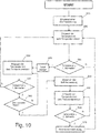
- Fig. 10 shows a flowchart in the operation of a heating device according to the invention, wherein an overheating is detected and as a countermeasure, a temperature control is carried out according to an embodiment of the invention.
- a target heating power of the apparatus is set. This can be done either manually, or automatically by specifying the heating / air conditioning unit, for example due to the evaluation of certain environmental parameters, in particular a temperature and specifications of a user, or because of the existing electrical system in the electrical system, for other purposes, such as traction , is not needed.
- step S52 the temperature of the PTC heating elements 30 is permanently monitored by means of a temperature sensor 70 according to the invention.
- a monitoring device determines in step S54 whether the measured temperature exceeds a predetermined threshold value (step S54). As long as this is not the case (S54: N), the monitoring device determines that a normal operating state exists, and no intervention is required.
- the temperature sensor 70 continues to detect the temperature continuously (S52).
- the monitoring device determines that an inadmissibly high operating temperature is present. If the threshold is exceeded only for a short time, this may be a random variation of the temperature. Otherwise, if the inadmissibly high temperature exists for a longer period of time, for example longer than about two minutes, however, an interruption or deceleration of the airflow, in particular a fan failure, can be assumed.
- the controller first starts a timer (time counting) in step S56, and the temperature is further detected by the temperature sensor 70 in step S58.
- the monitoring device further checks in step S60 whether the temperature is above the predetermined threshold value. If it is determined in step S54 or S60 that this is no longer the case (S54: N, S60: N), the process continues with the further detection of the temperature in step S52.
- step S60 shows that the temperature is still higher than the threshold value (S60: J)
- step S62 it is checked in subsequent step S62 whether the time measured by the timer since the first occurrence of the temperature exceeding the threshold value is greater than the specified period of time. If this is not (yet) the case (S62: N), the temperature is further detected in step S58 and compared with the threshold temperature in step S60. Otherwise (S62: J) it can be assumed that there is no random temperature fluctuation, but a disturbance of the air flow, and countermeasures have to be taken. In this case, the process goes to step S64 in which the (set) target heating power given in step S50 is lowered.
- the lowering of the desired heating power can be carried out in step S64 to zero, so the heating power are switched off completely.
- the shutdown or lowering of the heating power for example, stepwise or continuously, in particular linear, take place.
- either only an immediately affected heating circuit (whose temperature sensor has detected the inadmissible heating) or the entire heater can be reduced or switched off in their performance. It is also conceivable, for example, to make a corresponding decision dependent on the absolute level of the detected temperature, that is to say, for example, completely switch off the heating device if the determined temperature greatly exceeds the threshold value.
- the presence of a disturbance may be indicated by, for example, an audible and / or visual signal.
- the temperature is subsequently further detected in step S66 with the temperature sensor 70.
- the temperature is compared by the monitoring device after reducing or switching off the heating power with a second predetermined threshold, which is lower than the original threshold, when exceeded, the heating power has been lowered. If the monitoring device determines in step S68 that the temperature now falls below this second threshold value, the control device 15 is signaled that the heating power can be increased again in the subsequent step S70. Following this, the process returns to step S52.
- the present invention relates to an automotive electric heater for heating an air flow in which, for the purpose of avoiding improper heating, a surface temperature at the heat source (heating element or heat radiating radiator) is indirectly monitored by means of a temperature sensor.
- the temperature sensor is connected by means of a good heat conducting heat transfer element with the heat source.
- the temperature sensor itself is arranged separately from the heating block.
- no complete shutdown but a temperature control.
- a timer ensures that no adjustment of the heating power takes place with only short-term temperature fluctuations.
- a heater according to the invention is particularly suitable for automotive high voltage range, as in electric or hybrid vehicles of the case.
Landscapes
- Engineering & Computer Science (AREA)
- Physics & Mathematics (AREA)
- Mechanical Engineering (AREA)
- Thermal Sciences (AREA)
- General Engineering & Computer Science (AREA)
- Chemical & Material Sciences (AREA)
- Combustion & Propulsion (AREA)
- Automation & Control Theory (AREA)
- General Physics & Mathematics (AREA)
- Life Sciences & Earth Sciences (AREA)
- Sustainable Development (AREA)
- Sustainable Energy (AREA)
- Air-Conditioning For Vehicles (AREA)
Priority Applications (1)
| Application Number | Priority Date | Filing Date | Title |
|---|---|---|---|
| EP13156989.9A EP2772375B1 (fr) | 2013-02-27 | 2013-02-27 | Dispositif de chauffage électrique pour un véhicule automobile |
Applications Claiming Priority (1)
| Application Number | Priority Date | Filing Date | Title |
|---|---|---|---|
| EP13156989.9A EP2772375B1 (fr) | 2013-02-27 | 2013-02-27 | Dispositif de chauffage électrique pour un véhicule automobile |
Publications (2)
| Publication Number | Publication Date |
|---|---|
| EP2772375A1 true EP2772375A1 (fr) | 2014-09-03 |
| EP2772375B1 EP2772375B1 (fr) | 2017-10-18 |
Family
ID=47779895
Family Applications (1)
| Application Number | Title | Priority Date | Filing Date |
|---|---|---|---|
| EP13156989.9A Active EP2772375B1 (fr) | 2013-02-27 | 2013-02-27 | Dispositif de chauffage électrique pour un véhicule automobile |
Country Status (1)
| Country | Link |
|---|---|
| EP (1) | EP2772375B1 (fr) |
Cited By (5)
| Publication number | Priority date | Publication date | Assignee | Title |
|---|---|---|---|---|
| WO2016062631A1 (fr) * | 2014-10-21 | 2016-04-28 | Webasto SE | Dispositif de chauffage à capteur de température intégré |
| DE102017221490A1 (de) | 2017-11-30 | 2019-06-06 | Eberspächer Catem Gmbh & Co. Kg | Elektrische Heizvorrichtung |
| WO2020239423A1 (fr) * | 2019-05-27 | 2020-12-03 | Valeo Systemes Thermiques | Radiateur électrique de véhicule automobile équipé d'un dispositif de mesure de température |
| FR3103670A1 (fr) * | 2019-11-27 | 2021-05-28 | Valeo Systemes Thermiques | Radiateur électrique avec dispositif de mesure de température |
| DE102024118245A1 (de) * | 2024-06-27 | 2025-12-31 | Eberspächer Catem Gmbh & Co. Kg | Elektrische heizvorrichtung, klimasteuerungseinrichtung und verfahren zur steuerung einer heizleistung einer elektrischen heizvorrichtung |
Families Citing this family (2)
| Publication number | Priority date | Publication date | Assignee | Title |
|---|---|---|---|---|
| US20240208301A1 (en) * | 2021-04-28 | 2024-06-27 | Valeo Japan Co., Ltd. | Heating control device, control program, fluid heating unit, heating cycle device, and vehicle air conditioner including the same |
| FR3126650B1 (fr) * | 2021-09-03 | 2023-09-08 | Valeo Systemes Thermiques | Radiateur electrique pour une installation de ventilation, de chauffage et/ou de climatisation. |
Citations (4)
| Publication number | Priority date | Publication date | Assignee | Title |
|---|---|---|---|---|
| DE19918906A1 (de) * | 1999-04-26 | 2000-11-09 | Valeo Klimasysteme Gmbh | Temperatursensor |
| EP1350647B1 (fr) | 2002-03-28 | 2005-01-05 | Catem GmbH & Co.KG | Chauffage électrique pour un véhicule à moteur |
| EP1516761A1 (fr) | 2003-09-22 | 2005-03-23 | catem GmbH & Co.KG | Dispositif de chauffage électrique avec un capteur de température |
| EP2249618A1 (fr) * | 2008-01-30 | 2010-11-10 | Koshiro Taguchi | Radiateur monté dans un véhicule et procédé de fabrication |
-
2013
- 2013-02-27 EP EP13156989.9A patent/EP2772375B1/fr active Active
Patent Citations (5)
| Publication number | Priority date | Publication date | Assignee | Title |
|---|---|---|---|---|
| DE19918906A1 (de) * | 1999-04-26 | 2000-11-09 | Valeo Klimasysteme Gmbh | Temperatursensor |
| EP1350647B1 (fr) | 2002-03-28 | 2005-01-05 | Catem GmbH & Co.KG | Chauffage électrique pour un véhicule à moteur |
| EP1516761A1 (fr) | 2003-09-22 | 2005-03-23 | catem GmbH & Co.KG | Dispositif de chauffage électrique avec un capteur de température |
| US20050061798A1 (en) * | 2003-09-22 | 2005-03-24 | Catem Gmbh & Co. Kg | Electric heating apparatus with integrated temperatrure sensor |
| EP2249618A1 (fr) * | 2008-01-30 | 2010-11-10 | Koshiro Taguchi | Radiateur monté dans un véhicule et procédé de fabrication |
Cited By (15)
| Publication number | Priority date | Publication date | Assignee | Title |
|---|---|---|---|---|
| JP2019218052A (ja) * | 2014-10-21 | 2019-12-26 | ベバスト エスエーWebasto SE | 組み込まれた温度センサを有する加熱装置 |
| WO2016062631A1 (fr) * | 2014-10-21 | 2016-04-28 | Webasto SE | Dispositif de chauffage à capteur de température intégré |
| JP2017531588A (ja) * | 2014-10-21 | 2017-10-26 | ベバスト エスエーWebasto SE | 組み込まれた温度センサを有する加熱装置 |
| US20170313160A1 (en) * | 2014-10-21 | 2017-11-02 | Webasto SE | Heating device with integrated tempoerature sensor |
| KR20190052177A (ko) * | 2014-10-21 | 2019-05-15 | 베바스토 에스이 | 통합 온도 센서를 가진 가열 디바이스 |
| CN107076458A (zh) * | 2014-10-21 | 2017-08-18 | 韦巴斯托股份公司 | 具有集成的温度传感器的加热装置 |
| US11046151B2 (en) | 2014-10-21 | 2021-06-29 | Webasto SE | Heating device with integrated temperature sensor |
| DE102017221490A1 (de) | 2017-11-30 | 2019-06-06 | Eberspächer Catem Gmbh & Co. Kg | Elektrische Heizvorrichtung |
| WO2020239423A1 (fr) * | 2019-05-27 | 2020-12-03 | Valeo Systemes Thermiques | Radiateur électrique de véhicule automobile équipé d'un dispositif de mesure de température |
| FR3096763A1 (fr) * | 2019-05-27 | 2020-12-04 | Valeo Systemes Thermiques | Radiateur électrique de véhicule automobile équipé d’un dispositif de mesure de température |
| CN113727868A (zh) * | 2019-05-27 | 2021-11-30 | 法雷奥热系统公司 | 具有温度测量装置的机动车辆电散热器 |
| FR3103670A1 (fr) * | 2019-11-27 | 2021-05-28 | Valeo Systemes Thermiques | Radiateur électrique avec dispositif de mesure de température |
| WO2021105581A1 (fr) * | 2019-11-27 | 2021-06-03 | Valeo Systemes Thermiques | Radiateur electrique avec dispositif de mesure de temperature |
| US20220402334A1 (en) * | 2019-11-27 | 2022-12-22 | Valeo Systemes Thermiques | Electric radiator with temperature measurement device |
| DE102024118245A1 (de) * | 2024-06-27 | 2025-12-31 | Eberspächer Catem Gmbh & Co. Kg | Elektrische heizvorrichtung, klimasteuerungseinrichtung und verfahren zur steuerung einer heizleistung einer elektrischen heizvorrichtung |
Also Published As
| Publication number | Publication date |
|---|---|
| EP2772375B1 (fr) | 2017-10-18 |
Similar Documents
| Publication | Publication Date | Title |
|---|---|---|
| EP2772820B1 (fr) | Dispositif de chauffage électrique pour un véhicule automobile | |
| EP2772375B1 (fr) | Dispositif de chauffage électrique pour un véhicule automobile | |
| DE102017011428B4 (de) | Kühlsystem und Fahrzeug mit einem solchen Kühlsystem | |
| DE19930148B4 (de) | Temperatursteuerung in Elektrofahrzeug | |
| DE60307932T2 (de) | Vorrichtung und Verfahren zum Kontrollieren eines elektromotorisch angetriebenen Gebläses eines Kraftfahrzeuges | |
| DE19905072A1 (de) | Kraftfahrzeug-Klimaanlage mit Aufwärmsteuerung | |
| EP2732995B2 (fr) | Chauffage électrique pour véhicule automobile | |
| EP2863143B1 (fr) | Dispositif de chauffage | |
| DE102017213582A1 (de) | Lüftervorrichtung für ein Elektrogerät, Elektrogerät und Verfahren zur Steuerung derselben | |
| DE202011110647U1 (de) | Elektrische Fahrzeug-Heizvorrichtung | |
| DE102017218899A1 (de) | Elektrische Heizvorrichtung für ein Kraftfahrzeug | |
| DE102020206529A1 (de) | System zum Kühlen einer Batterie eines Kraftfahrzeugs, sowie Kraftfahrzeug | |
| DE112014004299T5 (de) | Fahrzeug-Klimatisierungsvorrichtung, Fahrzeug-Klimatisierungsheizeinrichtung und Fahrzeug-Klimatisierungsverfahren | |
| DE102021120776B4 (de) | Dachmodul zur Bildung eines Fahrzeugdachs mit einer Kühleinrichtung | |
| DE102009032621B4 (de) | PWM-gesteuerte PTC-Heizung hoher Kapazität | |
| EP4584119A1 (fr) | Prise de charge de véhicule et véhicule | |
| DE2308578B2 (de) | Zenlralheizungs- und -kühlanlage | |
| EP2838153B1 (fr) | Procédé d'homogénéisation de répartition de température des éléments de batterie lithium ion pour un véhicule automobile et batterie lithium-ion pour un véhicule automobile | |
| EP3294578A1 (fr) | Système de climatisation de véhicule et procédé de fonctionnement | |
| DE102011090195A1 (de) | Vorrichtung zur Temperierung eines Fahrzeuginnenraumes | |
| DE102011056476A1 (de) | Steuerverfahren für eine Unterheizung hoher Kapazität | |
| DE102009056041A1 (de) | Kühlerthermostat für ein Kraftfahrzeug mit elektrischem Heizelement | |
| DE112014005303B4 (de) | Anordnung und Verfahren zum Steuern der Temperatur eines Stromspeichersystems in einem Fahrzeug | |
| DE102022111447A1 (de) | Pulswechselrichter sowie Antriebsstrang und Verfahren zur Erwärmung eines Kühlmittels | |
| DE102004001849A1 (de) | Anbaustruktur für eine Halbleitervorrichtung an einer Hilfs-Heizeinrichtung |
Legal Events
| Date | Code | Title | Description |
|---|---|---|---|
| PUAI | Public reference made under article 153(3) epc to a published international application that has entered the european phase |
Free format text: ORIGINAL CODE: 0009012 |
|
| 17P | Request for examination filed |
Effective date: 20140724 |
|
| AK | Designated contracting states |
Kind code of ref document: A1 Designated state(s): AL AT BE BG CH CY CZ DE DK EE ES FI FR GB GR HR HU IE IS IT LI LT LU LV MC MK MT NL NO PL PT RO RS SE SI SK SM TR |
|
| AX | Request for extension of the european patent |
Extension state: BA ME |
|
| 17Q | First examination report despatched |
Effective date: 20161031 |
|
| GRAP | Despatch of communication of intention to grant a patent |
Free format text: ORIGINAL CODE: EPIDOSNIGR1 |
|
| RIC1 | Information provided on ipc code assigned before grant |
Ipc: B60H 1/00 20060101AFI20170608BHEP Ipc: H05B 3/42 20060101ALI20170608BHEP Ipc: G05D 23/19 20060101ALI20170608BHEP Ipc: G05D 23/20 20060101ALI20170608BHEP Ipc: F24H 9/20 20060101ALI20170608BHEP Ipc: F24H 3/04 20060101ALI20170608BHEP Ipc: B60H 1/22 20060101ALI20170608BHEP |
|
| INTG | Intention to grant announced |
Effective date: 20170629 |
|
| GRAS | Grant fee paid |
Free format text: ORIGINAL CODE: EPIDOSNIGR3 |
|
| GRAA | (expected) grant |
Free format text: ORIGINAL CODE: 0009210 |
|
| AK | Designated contracting states |
Kind code of ref document: B1 Designated state(s): AL AT BE BG CH CY CZ DE DK EE ES FI FR GB GR HR HU IE IS IT LI LT LU LV MC MK MT NL NO PL PT RO RS SE SI SK SM TR |
|
| REG | Reference to a national code |
Ref country code: GB Ref legal event code: FG4D Free format text: NOT ENGLISH |
|
| REG | Reference to a national code |
Ref country code: CH Ref legal event code: EP |
|
| REG | Reference to a national code |
Ref country code: AT Ref legal event code: REF Ref document number: 937601 Country of ref document: AT Kind code of ref document: T Effective date: 20171115 Ref country code: IE Ref legal event code: FG4D Free format text: LANGUAGE OF EP DOCUMENT: GERMAN |
|
| REG | Reference to a national code |
Ref country code: DE Ref legal event code: R096 Ref document number: 502013008575 Country of ref document: DE |
|
| REG | Reference to a national code |
Ref country code: NL Ref legal event code: MP Effective date: 20171018 |
|
| REG | Reference to a national code |
Ref country code: FR Ref legal event code: PLFP Year of fee payment: 6 |
|
| REG | Reference to a national code |
Ref country code: LT Ref legal event code: MG4D |
|
| PG25 | Lapsed in a contracting state [announced via postgrant information from national office to epo] |
Ref country code: NL Free format text: LAPSE BECAUSE OF FAILURE TO SUBMIT A TRANSLATION OF THE DESCRIPTION OR TO PAY THE FEE WITHIN THE PRESCRIBED TIME-LIMIT Effective date: 20171018 |
|
| PG25 | Lapsed in a contracting state [announced via postgrant information from national office to epo] |
Ref country code: SE Free format text: LAPSE BECAUSE OF FAILURE TO SUBMIT A TRANSLATION OF THE DESCRIPTION OR TO PAY THE FEE WITHIN THE PRESCRIBED TIME-LIMIT Effective date: 20171018 Ref country code: FI Free format text: LAPSE BECAUSE OF FAILURE TO SUBMIT A TRANSLATION OF THE DESCRIPTION OR TO PAY THE FEE WITHIN THE PRESCRIBED TIME-LIMIT Effective date: 20171018 Ref country code: ES Free format text: LAPSE BECAUSE OF FAILURE TO SUBMIT A TRANSLATION OF THE DESCRIPTION OR TO PAY THE FEE WITHIN THE PRESCRIBED TIME-LIMIT Effective date: 20171018 Ref country code: LT Free format text: LAPSE BECAUSE OF FAILURE TO SUBMIT A TRANSLATION OF THE DESCRIPTION OR TO PAY THE FEE WITHIN THE PRESCRIBED TIME-LIMIT Effective date: 20171018 Ref country code: NO Free format text: LAPSE BECAUSE OF FAILURE TO SUBMIT A TRANSLATION OF THE DESCRIPTION OR TO PAY THE FEE WITHIN THE PRESCRIBED TIME-LIMIT Effective date: 20180118 |
|
| PG25 | Lapsed in a contracting state [announced via postgrant information from national office to epo] |
Ref country code: RS Free format text: LAPSE BECAUSE OF FAILURE TO SUBMIT A TRANSLATION OF THE DESCRIPTION OR TO PAY THE FEE WITHIN THE PRESCRIBED TIME-LIMIT Effective date: 20171018 Ref country code: HR Free format text: LAPSE BECAUSE OF FAILURE TO SUBMIT A TRANSLATION OF THE DESCRIPTION OR TO PAY THE FEE WITHIN THE PRESCRIBED TIME-LIMIT Effective date: 20171018 Ref country code: GR Free format text: LAPSE BECAUSE OF FAILURE TO SUBMIT A TRANSLATION OF THE DESCRIPTION OR TO PAY THE FEE WITHIN THE PRESCRIBED TIME-LIMIT Effective date: 20180119 Ref country code: BG Free format text: LAPSE BECAUSE OF FAILURE TO SUBMIT A TRANSLATION OF THE DESCRIPTION OR TO PAY THE FEE WITHIN THE PRESCRIBED TIME-LIMIT Effective date: 20180118 Ref country code: LV Free format text: LAPSE BECAUSE OF FAILURE TO SUBMIT A TRANSLATION OF THE DESCRIPTION OR TO PAY THE FEE WITHIN THE PRESCRIBED TIME-LIMIT Effective date: 20171018 Ref country code: IS Free format text: LAPSE BECAUSE OF FAILURE TO SUBMIT A TRANSLATION OF THE DESCRIPTION OR TO PAY THE FEE WITHIN THE PRESCRIBED TIME-LIMIT Effective date: 20180218 |
|
| REG | Reference to a national code |
Ref country code: DE Ref legal event code: R097 Ref document number: 502013008575 Country of ref document: DE |
|
| PG25 | Lapsed in a contracting state [announced via postgrant information from national office to epo] |
Ref country code: EE Free format text: LAPSE BECAUSE OF FAILURE TO SUBMIT A TRANSLATION OF THE DESCRIPTION OR TO PAY THE FEE WITHIN THE PRESCRIBED TIME-LIMIT Effective date: 20171018 Ref country code: SK Free format text: LAPSE BECAUSE OF FAILURE TO SUBMIT A TRANSLATION OF THE DESCRIPTION OR TO PAY THE FEE WITHIN THE PRESCRIBED TIME-LIMIT Effective date: 20171018 Ref country code: DK Free format text: LAPSE BECAUSE OF FAILURE TO SUBMIT A TRANSLATION OF THE DESCRIPTION OR TO PAY THE FEE WITHIN THE PRESCRIBED TIME-LIMIT Effective date: 20171018 Ref country code: CZ Free format text: LAPSE BECAUSE OF FAILURE TO SUBMIT A TRANSLATION OF THE DESCRIPTION OR TO PAY THE FEE WITHIN THE PRESCRIBED TIME-LIMIT Effective date: 20171018 |
|
| PLBE | No opposition filed within time limit |
Free format text: ORIGINAL CODE: 0009261 |
|
| STAA | Information on the status of an ep patent application or granted ep patent |
Free format text: STATUS: NO OPPOSITION FILED WITHIN TIME LIMIT |
|
| PG25 | Lapsed in a contracting state [announced via postgrant information from national office to epo] |
Ref country code: SM Free format text: LAPSE BECAUSE OF FAILURE TO SUBMIT A TRANSLATION OF THE DESCRIPTION OR TO PAY THE FEE WITHIN THE PRESCRIBED TIME-LIMIT Effective date: 20171018 Ref country code: RO Free format text: LAPSE BECAUSE OF FAILURE TO SUBMIT A TRANSLATION OF THE DESCRIPTION OR TO PAY THE FEE WITHIN THE PRESCRIBED TIME-LIMIT Effective date: 20171018 Ref country code: PL Free format text: LAPSE BECAUSE OF FAILURE TO SUBMIT A TRANSLATION OF THE DESCRIPTION OR TO PAY THE FEE WITHIN THE PRESCRIBED TIME-LIMIT Effective date: 20171018 |
|
| REG | Reference to a national code |
Ref country code: CH Ref legal event code: PL |
|
| 26N | No opposition filed |
Effective date: 20180719 |
|
| PG25 | Lapsed in a contracting state [announced via postgrant information from national office to epo] |
Ref country code: MC Free format text: LAPSE BECAUSE OF FAILURE TO SUBMIT A TRANSLATION OF THE DESCRIPTION OR TO PAY THE FEE WITHIN THE PRESCRIBED TIME-LIMIT Effective date: 20171018 Ref country code: MT Free format text: LAPSE BECAUSE OF FAILURE TO SUBMIT A TRANSLATION OF THE DESCRIPTION OR TO PAY THE FEE WITHIN THE PRESCRIBED TIME-LIMIT Effective date: 20171018 |
|
| GBPC | Gb: european patent ceased through non-payment of renewal fee |
Effective date: 20180227 |
|
| REG | Reference to a national code |
Ref country code: IE Ref legal event code: MM4A |
|
| REG | Reference to a national code |
Ref country code: BE Ref legal event code: MM Effective date: 20180228 |
|
| PG25 | Lapsed in a contracting state [announced via postgrant information from national office to epo] |
Ref country code: CH Free format text: LAPSE BECAUSE OF NON-PAYMENT OF DUE FEES Effective date: 20180228 Ref country code: LU Free format text: LAPSE BECAUSE OF NON-PAYMENT OF DUE FEES Effective date: 20180227 Ref country code: LI Free format text: LAPSE BECAUSE OF NON-PAYMENT OF DUE FEES Effective date: 20180228 Ref country code: SI Free format text: LAPSE BECAUSE OF FAILURE TO SUBMIT A TRANSLATION OF THE DESCRIPTION OR TO PAY THE FEE WITHIN THE PRESCRIBED TIME-LIMIT Effective date: 20171018 |
|
| PG25 | Lapsed in a contracting state [announced via postgrant information from national office to epo] |
Ref country code: IE Free format text: LAPSE BECAUSE OF NON-PAYMENT OF DUE FEES Effective date: 20180227 |
|
| PG25 | Lapsed in a contracting state [announced via postgrant information from national office to epo] |
Ref country code: GB Free format text: LAPSE BECAUSE OF NON-PAYMENT OF DUE FEES Effective date: 20180227 Ref country code: BE Free format text: LAPSE BECAUSE OF NON-PAYMENT OF DUE FEES Effective date: 20180228 |
|
| REG | Reference to a national code |
Ref country code: AT Ref legal event code: MM01 Ref document number: 937601 Country of ref document: AT Kind code of ref document: T Effective date: 20180227 |
|
| PG25 | Lapsed in a contracting state [announced via postgrant information from national office to epo] |
Ref country code: AT Free format text: LAPSE BECAUSE OF NON-PAYMENT OF DUE FEES Effective date: 20180227 |
|
| PG25 | Lapsed in a contracting state [announced via postgrant information from national office to epo] |
Ref country code: TR Free format text: LAPSE BECAUSE OF FAILURE TO SUBMIT A TRANSLATION OF THE DESCRIPTION OR TO PAY THE FEE WITHIN THE PRESCRIBED TIME-LIMIT Effective date: 20171018 |
|
| PG25 | Lapsed in a contracting state [announced via postgrant information from national office to epo] |
Ref country code: HU Free format text: LAPSE BECAUSE OF FAILURE TO SUBMIT A TRANSLATION OF THE DESCRIPTION OR TO PAY THE FEE WITHIN THE PRESCRIBED TIME-LIMIT; INVALID AB INITIO Effective date: 20130227 Ref country code: PT Free format text: LAPSE BECAUSE OF FAILURE TO SUBMIT A TRANSLATION OF THE DESCRIPTION OR TO PAY THE FEE WITHIN THE PRESCRIBED TIME-LIMIT Effective date: 20171018 |
|
| PG25 | Lapsed in a contracting state [announced via postgrant information from national office to epo] |
Ref country code: MK Free format text: LAPSE BECAUSE OF NON-PAYMENT OF DUE FEES Effective date: 20171018 Ref country code: CY Free format text: LAPSE BECAUSE OF FAILURE TO SUBMIT A TRANSLATION OF THE DESCRIPTION OR TO PAY THE FEE WITHIN THE PRESCRIBED TIME-LIMIT Effective date: 20171018 |
|
| PG25 | Lapsed in a contracting state [announced via postgrant information from national office to epo] |
Ref country code: AL Free format text: LAPSE BECAUSE OF FAILURE TO SUBMIT A TRANSLATION OF THE DESCRIPTION OR TO PAY THE FEE WITHIN THE PRESCRIBED TIME-LIMIT Effective date: 20171018 |
|
| REG | Reference to a national code |
Ref country code: FR Ref legal event code: PLFP Year of fee payment: 10 |
|
| PGFP | Annual fee paid to national office [announced via postgrant information from national office to epo] |
Ref country code: IT Payment date: 20220228 Year of fee payment: 10 Ref country code: FR Payment date: 20220221 Year of fee payment: 10 |
|
| PG25 | Lapsed in a contracting state [announced via postgrant information from national office to epo] |
Ref country code: IT Free format text: LAPSE BECAUSE OF NON-PAYMENT OF DUE FEES Effective date: 20230227 Ref country code: FR Free format text: LAPSE BECAUSE OF NON-PAYMENT OF DUE FEES Effective date: 20230228 |
|
| PGFP | Annual fee paid to national office [announced via postgrant information from national office to epo] |
Ref country code: DE Payment date: 20260217 Year of fee payment: 14 |