EP1517072A1 - Ventil - Google Patents
Ventil Download PDFInfo
- Publication number
- EP1517072A1 EP1517072A1 EP03021343A EP03021343A EP1517072A1 EP 1517072 A1 EP1517072 A1 EP 1517072A1 EP 03021343 A EP03021343 A EP 03021343A EP 03021343 A EP03021343 A EP 03021343A EP 1517072 A1 EP1517072 A1 EP 1517072A1
- Authority
- EP
- European Patent Office
- Prior art keywords
- valve according
- valve
- groove
- support
- carrier
- Prior art date
- Legal status (The legal status is an assumption and is not a legal conclusion. Google has not performed a legal analysis and makes no representation as to the accuracy of the status listed.)
- Granted
Links
- 238000007789 sealing Methods 0.000 claims abstract description 70
- 125000006850 spacer group Chemical group 0.000 claims description 12
- 238000004873 anchoring Methods 0.000 claims 1
- 239000012530 fluid Substances 0.000 description 10
- 238000013461 design Methods 0.000 description 5
- 239000000463 material Substances 0.000 description 5
- 238000009434 installation Methods 0.000 description 4
- 238000009826 distribution Methods 0.000 description 3
- 238000003780 insertion Methods 0.000 description 3
- 230000037431 insertion Effects 0.000 description 3
- 238000004519 manufacturing process Methods 0.000 description 3
- 238000011144 upstream manufacturing Methods 0.000 description 3
- 238000010276 construction Methods 0.000 description 2
- 238000000034 method Methods 0.000 description 2
- 230000036316 preload Effects 0.000 description 2
- 230000003213 activating effect Effects 0.000 description 1
- 230000009286 beneficial effect Effects 0.000 description 1
- 230000006835 compression Effects 0.000 description 1
- 238000007906 compression Methods 0.000 description 1
- 230000001419 dependent effect Effects 0.000 description 1
- 230000001627 detrimental effect Effects 0.000 description 1
- 238000011161 development Methods 0.000 description 1
- 230000018109 developmental process Effects 0.000 description 1
- 238000006073 displacement reaction Methods 0.000 description 1
- 230000000694 effects Effects 0.000 description 1
- 239000013013 elastic material Substances 0.000 description 1
- 238000001746 injection moulding Methods 0.000 description 1
- 230000003993 interaction Effects 0.000 description 1
- 238000005304 joining Methods 0.000 description 1
- 239000002184 metal Substances 0.000 description 1
- 238000002360 preparation method Methods 0.000 description 1
- 238000003825 pressing Methods 0.000 description 1
- 230000000630 rising effect Effects 0.000 description 1
- 230000006641 stabilisation Effects 0.000 description 1
- 238000011105 stabilization Methods 0.000 description 1
- 230000007704 transition Effects 0.000 description 1
- 238000013022 venting Methods 0.000 description 1
Images


Classifications
-
- F—MECHANICAL ENGINEERING; LIGHTING; HEATING; WEAPONS; BLASTING
- F16—ENGINEERING ELEMENTS AND UNITS; GENERAL MEASURES FOR PRODUCING AND MAINTAINING EFFECTIVE FUNCTIONING OF MACHINES OR INSTALLATIONS; THERMAL INSULATION IN GENERAL
- F16K—VALVES; TAPS; COCKS; ACTUATING-FLOATS; DEVICES FOR VENTING OR AERATING
- F16K11/00—Multiple-way valves, e.g. mixing valves; Pipe fittings incorporating such valves
- F16K11/02—Multiple-way valves, e.g. mixing valves; Pipe fittings incorporating such valves with all movable sealing faces moving as one unit
- F16K11/06—Multiple-way valves, e.g. mixing valves; Pipe fittings incorporating such valves with all movable sealing faces moving as one unit comprising only sliding valves, i.e. sliding closure elements
- F16K11/065—Multiple-way valves, e.g. mixing valves; Pipe fittings incorporating such valves with all movable sealing faces moving as one unit comprising only sliding valves, i.e. sliding closure elements with linearly sliding closure members
- F16K11/07—Multiple-way valves, e.g. mixing valves; Pipe fittings incorporating such valves with all movable sealing faces moving as one unit comprising only sliding valves, i.e. sliding closure elements with linearly sliding closure members with cylindrical slides
- F16K11/0712—Multiple-way valves, e.g. mixing valves; Pipe fittings incorporating such valves with all movable sealing faces moving as one unit comprising only sliding valves, i.e. sliding closure elements with linearly sliding closure members with cylindrical slides comprising particular spool-valve sealing means
Definitions
- the invention relates to a valve, with a valve housing, one provided for receiving at least one valve slide, circumferentially bounded by a housing wall elongated Housing recess, in the laterally at least a valve channel opens and in one of the valve slide interspersed sealing device is arranged, the at least a sealing unit having an annular Carrier has one for sealing against the Serving valve spool annular inner seal and a in an outer annular groove arranged, opposite to the seal the housing wall serving annular, rubber-elastic outer seal wearing.
- a known from DE 34 08 182 C2 known valve of this type one arranged in an elongated housing recess Seal device consisting of several axially spaced Gasket units composed.
- Each seal unit has a one-piece, annular support, the Inner circumference of an annular inner seal receiving inner annular groove and on the outer circumference an annular outer seal having receiving outer annular groove.
- the inner seal cooperates with a seal units enforcing axially adjustable valve slide.
- the outer seal lies under seal at the radially inward orientation Wall surface of the housing recess defining housing wall at. The installation of the individual sealing units happens by coaxial insertion into the housing recess to the desired location.
- valve channels In the housing recess open laterally more valve channels one. Be the sealing units during assembly of the valve inserted into the housing recess, so slide the Outer seals of some seal units over the channel mouths time. This can damage the outer seal so that the desired sealing function is no longer guaranteed is.
- the carrier in Area of the outer annular groove in two axially successive Carrier parts is divided, wherein a first carrier part the Groove base and the one, first groove flank and a second support part the other, second groove edge of the outer annular groove defines and wherein at the first support part is a via a Ramp surface in coaxial extension to the groove base subsequent Provision area with compared to the groove bottom smaller diameter is provided by the second Carrier part is overlapped, such that one on the staging area placed outer seal during axial assembly the two support parts over the ramp surface away displaced under radial expansion on the groove base is.
- the at least one sealing unit at the assembly of the valve at the desired nominal position in Inside the housing recess can be placed without doing so the outer seal from the edges of the channel mouths of damaged in the housing recess opening valve channels becomes.
- the risk of damage to the outer seal be reduced.
- the embodiment can be made such that the first Carrier part with outer seal placed on the delivery surface regardless of the assigned second carrier part in the housing recess is placed and only then the second carrier part is attached. It is possible also, the second carrier part together with the already in it a starting position prefixed second carrier part in the Insert housing recess, then the two support parts fully assemble, so that the outer seal in the area of a larger diameter groove bottom is moved.
- the sealing units are not mandatory must be determined in the press fit in the housing recess, there is a largely free choice of material for the valve housing, so that it is also possible in particular, the housing wall made of plastic material.
- a secure fixation of the outer seal on the staging area can be favored by the provisioning area a concentric to the groove bottom annular Deepening forms, in which the outer seal (also) positive fit is held.
- the outer seal designed as an O-ring. This slides when squeezed the two support parts particularly reliable over the Ramp away on the groove bottom of the outer ring groove.
- annular inner seal in held an annular groove of the wearer.
- the number of seal units is based on the design and in particular the functionality of the valve. Accordingly the valve is usually several coaxial having spaced apart seal units. These are preferably arranged such that the second carrier part the one sealing unit in each case the first Carrier part of the axially adjacent sealing unit adjacent is.
- the installation of several sealing units is very easy with high precision possible when the axially adjacent support parts the carrier of two successive sealing units are mutually supported axially.
- This can support for example, by means of the distance bridging spacer means done or by the summary of the relevant carrier parts to a rigid, in particular integral carrier unit. Ensuring the support measures that the individual sealing units a predetermined Keep distance to each other on the distribution the channel mouths of the valve channels along the housing recess is tuned.
- FIG. 1 shows a valve 1 as part of a total designated by reference numeral 2 valve assembly, in addition still on a preferred plate-like trained Fluid distributor 3 has, on which the valve 1 releasably, by means of suitable fasteners 4, is attached.
- the valve 1 is used to control fluid flows and is as Multi-way valve executed.
- the medium to be controlled acts it is in particular compressed air, although it is also to another gaseous or hydraulic Medium can act.
- the valve 1 has a valve housing 5 in which at least a linearly extending, elongated housing recess 6 is provided. On the circumference is the housing recess 6 bounded by a housing wall 7 of the valve housing 5.
- the housing wall 7 and in particular the entire valve housing 5 exist in the embodiment of plastic material.
- the preparation is advantageously carried out by injection molding, wherein a reworking of the housing recess. 6 defining and radially inwardly oriented wall surface. 8 the housing wall 7 is not required or only to a small extent is. A design made of metal would in principle also possible.
- valve channels 12 a In the housing recess 6 open in the region of the wall surface. 8 at a plurality in the longitudinal direction of the housing recess 6 spaced locations valve channels 12 a. Enforce this the housing wall 7 and form at its outer end connection openings 13. Three of these connection openings 13 lead to a outer mounting surface 14 of the valve housing 5, with the valve 1 to a mounting surface 15 of the fluid distributor 3 is set. In the latter run several fluid distribution channels 16, which lead to the mounting surface 15 and communicate there with the connection openings 13 in pairs.
- connection openings 13 open at one of Mounting surface 14 in particular opposite pad 17 of the valve housing 5 and are provided, the connection to allow not shown fluid lines, lead to a consumer to be driven.
- valve 1 of the embodiment is a 5/2-way valve.
- Valve channels 12 At the opening to the mounting surface 4 Valve channels 12 is a middle feed channel 12a, the axially on both sides of a respective venting channel 12b, 12c is flanked.
- the two to the final surface 17 leading valve channels 12 are working channels 12d, 12e.
- valves 1 On the fluid distributor 3, a plurality of valves 1 can be positioned be, each assignment correctly with the fluid distribution channels 16 are connected.
- Valve Gate 18 In the housing recess 6 there is an elongated piston-like Valve Gate 18. It has several control sections 22 larger diameter, between each one Control portion 23 of smaller diameter is placed. the Valve slide 18 associated actuation means 24 allow an axial displacement and positioning of the valve slide 18 in the housing recess 6 relative to the valve housing 5th
- the on the valve spool 18 opposite side of the Actuating piston 25 lying outer portion 27 of the operating space 26 communicates to not shown Way with a control channel 28 through which a fluidic Control medium can be either fed or discharged.
- the corresponding controller adopts an electrically activatable Pilot valve 32 which is attached to the valve housing 5 is.
- Comparable actuators may also be the opposite Be assigned to the end of the valve spool 18. deviant However, this is there in the embodiment, however only one return spring 33, between the valve housing 5 and the valve spool 18 is effective and the valve spool 18 constantly in the direction of the actuating piston 27th applied.
- the housing recess 6 is closed at both ends. On at least one front side of the closure takes place by a cover plate detachably fastened to the valve housing 5 34. In the removed state of the closure lid 34 is the housing recess 6 from the corresponding end side accessible.
- the sealing device 35 contains at least one and in usually several sealing units 36, of which in the embodiment five pieces are available.
- the sealing units 36 are each annular.
- the sealing units 36 are thus at an axial distance in the housing recess 6 arranged that each other adjacent sealing units 36 a recess portion 37 of the housing recess 6 defined with one of the valve channels 12 in Connection stands.
- the valve channels 12 open with channel mouths 38 laterally in the housing recess 6 a.
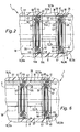
- annular, dimensionally stable carrier 41 which consists of two annular, coaxially joined together first and second support parts 42, 43 composed.
- the two support parts 42, 43 define together one open to the outer circumference outer annular groove 44 and an inner periphery open towards the inner Ring groove 45.
- annular rubber gasket material consisting of outer seal 46, in particular an O-ring, the with sealing contact the inner surface of the outer annular groove 44 and on the wall surface 8 is applied to a fluid passage between the housing wall 7 and the carrier 41 to prevent.
- Inner gasket 47 In the inner annular groove 45 concentrically sits an annular, preferably also made of rubber-elastic material Inner gasket 47. This is in sealing contact with the inner surface of the inner annular groove 45 and with the outer surface of the momentarily passing through the seal unit 36 Control section 22 of larger diameter of the valve spool 18th
- each carrier 41 is forming the two Carrier parts 42, 43 in the region of the outer annular groove 44 and preferably also the inner annular groove 45 in the ring plane, i.e. divided at right angles to the longitudinal axis.
- the dividing line runs so that the one, first groove flank 48, 53 and the groove bottom 50, 55 of the outer and inner annular groove 44, 45 provided on the first support member 42 is, while the other, second groove flank 49, 54 of the outer and inner annular groove 44, 45 located on the second support member 43.
- the groove bottom 50 of the outer annular groove 44 is radially outwardly oriented, while the groove bottom 55 of the inner Ring groove 45 points radially inward.
- the two carrier parts 42, 43 are preferably coaxial with each other arranged ring parts executed.
- On both support parts 42, 43 is axially adjacent to the outer Ring groove 44 each have a radially outwardly facing circumferential Support surface 56 a, 56 b, for supporting the relevant Carrier part 42, 43 at the radially inwardly oriented Wall surface 8 of the housing wall 7 is used.
- the outer seal 46 thus assumes only a sealing function, while the Stabilization of the position of the sealing device 45 via the support surfaces 56a, 56b is realized.
- Preferred are the support surfaces 56a, 56b so in terms of their design matched to the cross section of the housing recess 6, that the support members 42, 43 substantially free of play in the housing recess 6 are inserted.
- the aforementioned groove bottom 50 in the direction is upstream of the second support member 43 at a distance. It is, as well as the groove bottom 50, oriented radially outward, wherein they one compared to the groove bottom 50 of the outer Ring groove 44 has a smaller diameter.
- the transition between the groove bottom 50 and the delivery surface 57th forms a concentrically arranged annular ramp surface 58, which is for example a conical surface can act and, seen in cross-section, starting from the supply surface 57 to the groove bottom 50 increases.
- the diameter of the groove bottom 50 of the outer seal 46 is so on the radial cross-sectional dimensions of the outer seal 46th tuned that these when in the outer annular groove 44 sits, squeezed between the groove bottom 50 and the wall surface 8 is, and thus complies with their Abdichtaufgabe.
- the outer seal 46 also when inserting a sealing unit 36 in the housing recess 6 in the outer Ring groove 44 sitting, she would be in direct contact with Wall surface 8 slide along this and when crossing a channel mouth 38 come into contact with the edges thereof. Since the outer seal 46 temporarily in the channel mouth could extend into contact with the Muzzle edge damage occurs, the desired Abdichtfunktion would be detrimental.
- the first support member 42 according to Arrow 62 inserted into the housing recess 6, wherein previously the outer seal 64 concentric on the delivery surface 57 has been placed. Because these have a smaller diameter has as the groove bottom 50, the outer seal 46 not or only slightly radially stretched, so that their outer diameter is less than the inner diameter of the housing recess 6. Thus remains between the outer seal 46th and the wall surface 8 of the housing recess 6 an annular gap 63, the 43 during insertion of the second support member a Contact between the outer seal 46 and the housing wall 7 and in particular with the edges of the channel mouths 38 prevented.
- a positive Fixation achieved by the provision of surface 57th is shaped in such a way that concentric to the groove bottom annular recess 63 results. Into these dives the outer seal 46 with a part of its cross-sectional circumference a positive fit.
- the ramp surface 58 may simultaneously be a part of the recess 63 defining area.
- the equipped with the outer seal 46 first support member 42nd is axially to the desired position desired in the housing recess 6 inserted.
- This target position is in the embodiment specified by support means 64, the Limit insertion path of the first support member 42.
- the support means 46 of a gradation 65 of Housing recess 6 is formed. The first one is based on this Carrier part 42 frontally with the staging area 57 opposite end face off.
- first 36 forms this in turn support means 64 to axially correct positioning of the next to be installed Sealing unit.
- first 36 forms this in turn support means 64 to axially correct positioning of the next to be installed Sealing unit.
- the here of several pin-like or rod-like spacer struts 74 are formed on the second support member 43 are attached and starting from this in the first Support member 42 extend opposite axial direction.
- more than the circumference of second support part 43 distributed spacer struts 74 provided at the second groove flanks 49, 54 opposite Front side of the second support part 43 in particular are integrally formed.
- the spacer struts 74 span between adjacent ones Sealing units 36 located recess portion 37 of the housing recess 6, wherein due to the between long distances provided for them, but an undisturbed one fluidic connection between the respective recess portion 37 and the opening into this valve channel 12 is ensured.
- the spacer means 73 could also be relative to the support parts 42, 43 be separate components. For example they could be part of a cage-like ring element be that between each successive sealing units 36 is used.
- Preferred is it is a one-piece unit. Due to the Spacer struts 74, the carrier subunit 78 a have cage-like structure. The advantage of such a carrier subunit 78 is that at the same time as the assembly the second support part 43 of a sealing unit 36 the Mounting the already pre-equipped with an outer seal 46 first support part 42 of the subsequent seal unit 36 can be made.
- the sealing units 36 to install so that the axially adjacent support parts two successive sealing units are formed identically, it is considered to be particularly advantageous considered to make the arrangement so that at two axially successive seal units 36 each one first support part 42 of a sealing unit 36 a second support part 43 of the subsequent sealing unit 36 is adjacent. In the longitudinal direction of the sealing device This results in an alternating succession first and second support parts 42, 43.
Landscapes
- Engineering & Computer Science (AREA)
- General Engineering & Computer Science (AREA)
- Mechanical Engineering (AREA)
- Multiple-Way Valves (AREA)
- Valve Housings (AREA)
Abstract
Description
- Figur 1
- eine bevorzugte Ausführungsform des erfindungsgemäßen Ventils im Längsschnitt,
- Figur 2
- den in Figur strichpunktiert markierten Ausschnitt II in vergrößerter Darstellung,
- Figuren 3 bis 5
- verschieden Phasen der Montage einer Dichtungseinheit in der Gehäuseausnehmung des Ventils und
- Figur 6
- einen der Figur 2 entsprechenden Ausschnitt des Ventils aus Figur 1, das mit einer abgewandelten Bauform der Dichtungseinrichtung ausgestattet ist.
Claims (21)
- Ventil mit einem Ventilgehäuse (5), das eine zur Aufnahme wenigstens eines Ventilschiebers (18) vorgesehene, umfangsseitig von einer Gehäusewand (7) begrenzte längliche Gehäuseausnehmung (6) aufweist, in die seitlich mindestens ein Ventilkanal (12) einmündet und in der eine vom Ventilschieber (18) durchsetzte Dichtungseinrichtung (35) angeordnet ist, die mindestens eine Dichtungseinheit (36) aufweist, die über einen ringförmigen Träger (41) verfügt, der eine zur Abdichtung gegenüber dem Ventilschieber (18) dienende ringförmige Innendichtung (47) und eine in einer äußeren Ringnut (44) angeordnete, zur Abdichtung gegenüber der Gehäusewand (7) dienende ringförmige, gummielastische Außendichtung (46) trägt, dadurch gekennzeichnet, dass der Träger (41) im Bereich der äußeren Ringnut (44) in zwei axial aufeinanderfolgende Trägerteile (42, 43) unterteilt ist, wobei ein erstes Trägerteil (42) den Nutgrund (50) und die eine, erste Nutflanke (48) und ein zweites Trägerteil (43) die andere, zweite Nutflanke (49) der äußeren Ringnut (44) definiert und wobei an dem ersten Trägerteil (42) eine sich über eine Rampenfläche (58) in koaxialer Verlängerung an den Nutgrund (50) anschließende Bereitstellungsfläche (57) mit im Vergleich zum Nutgrund (50) geringerem Durchmesser vorgesehen ist, die vom zweiten Trägerteil (42) übergriffen wird, derart, dass eine auf der Bereitstellungsfläche (57) platzierte Außendichtung (46) beim axialen Zusammenfügen der beiden Trägerteile (42, 43) über die Rampenfläche (58) hinweg unter radialer Aufweitung auf den Nutgrund (50) verlagerbar ist.
- Ventil nach Anspruch 1, dadurch gekennzeichnet, dass der Innendurchmesser der Gehäuseabnehmung (6) größer ist als der Außendurchmesser der auf der Bereitstellungsfläche (57) sitzendend Außendichtung (46).
- Ventil nach Anspruch 1 oder 2, dadurch gekennzeichnet, dass die Außendichtung (46) unter radialer Vorspannung auf der Bereitstellungsfläche (57) gehalten ist.
- Ventil nach einem der Ansprüche 1 bis 3, dadurch gekennzeichnet, dass die Bereitstellungsfläche (57) eine zum Nutgrund (50) konzentrische ringförmige Vertiefung (63) definiert.
- Ventil nach einem der Ansprüche 1 bis 4, dadurch gekennzeichnet, dass das zweite Trägerteil (43) koaxial lösbar auf das erste Trägerteil (42) aufgesteckt ist.
- Ventil nach einem der Ansprüche 1 bis 5, dadurch gekennzeichnet, dass die Außendichtung (46) ein O-Ring ist.
- Ventil nach einem der Ansprüche 1 bis 6, dadurch gekennzeichnet, dass die ringförmige Innendichtung (47) in einer inneren Ringnut (45) des Trägers (41) gehalten ist.
- Ventil nach Anspruch 7, dadurch gekennzeichnet, dass sich die Unterteilung des Trägers (41) auch auf die innere Ringnut (45) erstreckt, wobei die innere Ringnut (45) einen Nutgrund (55), eine am ersten Trägerteil (42) vorgesehene erste Nutflanke(53) und eine am zweiten Trägerteil (43) vorgesehene zweite Nutflanke (54) aufweist.
- Ventil nach Anspruch 8, dadurch gekennzeichnet, dass der Nutgrund (55) der inneren Ringnut (45) zumindest teilweise am ersten Trägerteil (42) vorgesehen ist, derart, dass die Innendichtung (47) bei entferntem zweitem Trägerteil (43) durch Zusammenwirken mit dem Nutgrund (55) an dem ersten Trägerteil (42) fixierbar ist.
- Ventil nach einem der Ansprüche 1 bis 9, dadurch gekennzeichnet, dass die beiden Trägerteile (42, 43) zwei koaxial zueinander angeordnete Ringteile sind.
- Ventil nach einem der Ansprüche 1 bis 10, dadurch gekennzeichnet, dass die Dichtungseinrichtung (35) mehrere koaxial mit Abstand zueinander angeordnete Dichtungseinheiten (36) aufweist.
- Ventil nach Anspruch 11, dadurch gekennzeichnet, dass die Dichtungseinheiten (36) so angeordnet sind, dass das zweite Trägerteil (43) der jeweils einen Dichtungseinheit (35) dem ersten Trägerteil (42) der axial darauffolgenden Dichtungseinheit (36) benachbart ist.
- Ventil nach Anspruch 11 oder 12, dadurch gekennzeichnet, dass die axial benachbarten Trägerteile (42, 43) der Träger (41) zweier jeweils aufeinanderfolgender Dichtungseinheiten (36) gegenseitig axial abgestützt sind.
- Ventil nach einem der Ansprüche 11 bis 13, dadurch gekennzeichnet, dass sich zwischen den benachbarten Trägerteilen (42, 43) zweier aufeinanderfolgender Dichtungseinheiten (36) Abstandshaltemittel (73) erstrecken.
- Ventil nach Anspruch 14, dadurch gekennzeichnet, dass die Abstandshaltemittel (73) strebenartig ausgebildet sind.
- Ventil nach Anspruch 15, dadurch gekennzeichnet, dass die benachbarten Trägerteile (42, 43) zweier aufeinanderfolgender Dichtungseinheiten (36) zu einer starren Trägerteileinheit (78) zusammengefasst sind.
- Ventil nach einem der Ansprüche 11 bis 16, dadurch gekennzeichnet, dass zwischen mehreren aufeinanderfolgenden Dichtungseinheiten (36) jeweils eine Kanalmündung (38) eines in die Gehäuseausnehmung (6) einmündenden Ventilkanals (12) vorgesehen ist.
- Ventil nach einem der Ansprüche 1 bis 17, dadurch gekennzeichnet, dass die Gehäuseausnehmung (6) eine Abstufung (65) aufweist, an der sich die Dichtungseinrichtung (35) stirnseitig einenends abstützen kann.
- Ventil nach Anspruch 18, gekennzeichnet durch ein die Dichtungseinrichtung (35) andernends stirnseitig abstützendes, ventilgehäusefest verankertes Sicherungsteil (76).
- Ventil nach einem der Ansprüche 1 bis 19, dadurch gekennzeichnet, dass beide Trägerteile (42, 43) benachbart zur äußeren Ringnut (44) jeweils eine nach radial außen weisende, zur Abstützung an der nach radial innen orientierten Wandfläche (8) der Gehäusewand (7) dienende umlaufende Abstützfläche (56a, 56b) aufweisen.
- Ventil nach einem der Ansprüche 1 bis 20, dadurch gekennzeichnet, dass die Rampenfläche (58) als konisch gestaltete Ringfläche ausgeführt ist.
Priority Applications (2)
| Application Number | Priority Date | Filing Date | Title |
|---|---|---|---|
| EP20030021343 EP1517072B1 (de) | 2003-09-20 | 2003-09-20 | Ventil |
| DE50308228T DE50308228D1 (de) | 2003-09-20 | 2003-09-20 | Ventil |
Applications Claiming Priority (1)
| Application Number | Priority Date | Filing Date | Title |
|---|---|---|---|
| EP20030021343 EP1517072B1 (de) | 2003-09-20 | 2003-09-20 | Ventil |
Publications (2)
| Publication Number | Publication Date |
|---|---|
| EP1517072A1 true EP1517072A1 (de) | 2005-03-23 |
| EP1517072B1 EP1517072B1 (de) | 2007-09-19 |
Family
ID=34178463
Family Applications (1)
| Application Number | Title | Priority Date | Filing Date |
|---|---|---|---|
| EP20030021343 Expired - Lifetime EP1517072B1 (de) | 2003-09-20 | 2003-09-20 | Ventil |
Country Status (2)
| Country | Link |
|---|---|
| EP (1) | EP1517072B1 (de) |
| DE (1) | DE50308228D1 (de) |
Cited By (1)
| Publication number | Priority date | Publication date | Assignee | Title |
|---|---|---|---|---|
| CN101813202B (zh) * | 2009-01-21 | 2012-06-20 | Smc株式会社 | 切换阀装置 |
Families Citing this family (1)
| Publication number | Priority date | Publication date | Assignee | Title |
|---|---|---|---|---|
| DE102015221940B3 (de) * | 2015-11-09 | 2016-10-20 | Festo Ag & Co. Kg | Ventilanordnung |
Citations (6)
| Publication number | Priority date | Publication date | Assignee | Title |
|---|---|---|---|---|
| FR1173092A (fr) * | 1957-03-20 | 1959-02-19 | Valvair Corp | Distributeur à fluide |
| CH393015A (de) * | 1964-04-23 | 1965-05-31 | Nostorag Ag | Mehrweg-Steuerschieber |
| US3680596A (en) * | 1970-12-28 | 1972-08-01 | Ross Operating Valve Co | Resilient seal spool valve |
| GB1333468A (en) * | 1970-03-21 | 1973-10-10 | Buerkert C | Multi-way valves |
| DE3114129A1 (de) * | 1981-04-08 | 1982-11-04 | Prädifa Präzisions-Dichtungs-Fabrik GmbH, 7120 Bietigheim-Bissingen | Dichtung |
| DE3839424A1 (de) * | 1988-11-23 | 1990-05-31 | Gewerk Eisenhuette Westfalia | Mehrwegeventil, insbesondere elektromagnetisch betaetigtes ventil fuer ausbausteuerungen |
-
2003
- 2003-09-20 EP EP20030021343 patent/EP1517072B1/de not_active Expired - Lifetime
- 2003-09-20 DE DE50308228T patent/DE50308228D1/de not_active Expired - Lifetime
Patent Citations (6)
| Publication number | Priority date | Publication date | Assignee | Title |
|---|---|---|---|---|
| FR1173092A (fr) * | 1957-03-20 | 1959-02-19 | Valvair Corp | Distributeur à fluide |
| CH393015A (de) * | 1964-04-23 | 1965-05-31 | Nostorag Ag | Mehrweg-Steuerschieber |
| GB1333468A (en) * | 1970-03-21 | 1973-10-10 | Buerkert C | Multi-way valves |
| US3680596A (en) * | 1970-12-28 | 1972-08-01 | Ross Operating Valve Co | Resilient seal spool valve |
| DE3114129A1 (de) * | 1981-04-08 | 1982-11-04 | Prädifa Präzisions-Dichtungs-Fabrik GmbH, 7120 Bietigheim-Bissingen | Dichtung |
| DE3839424A1 (de) * | 1988-11-23 | 1990-05-31 | Gewerk Eisenhuette Westfalia | Mehrwegeventil, insbesondere elektromagnetisch betaetigtes ventil fuer ausbausteuerungen |
Cited By (3)
| Publication number | Priority date | Publication date | Assignee | Title |
|---|---|---|---|---|
| CN101813202B (zh) * | 2009-01-21 | 2012-06-20 | Smc株式会社 | 切换阀装置 |
| TWI394908B (zh) * | 2009-01-21 | 2013-05-01 | Smc Corp | 切換閥裝置 |
| DE102010005126B4 (de) | 2009-01-21 | 2019-04-11 | Smc Corp. | Auswahlventileinrichtung |
Also Published As
| Publication number | Publication date |
|---|---|
| EP1517072B1 (de) | 2007-09-19 |
| DE50308228D1 (de) | 2007-10-31 |
Similar Documents
| Publication | Publication Date | Title |
|---|---|---|
| EP1291563B1 (de) | Rückschlagventil sowie Ventil mit einem solchen Rückschlagventil | |
| DE2357671C2 (de) | Durchflußbegrenzungsventil | |
| EP1391640A1 (de) | Dichtungsring | |
| WO2003074912A1 (de) | Kombiniertes rückschlag- und überdruckventil | |
| DE10203886A1 (de) | Vorsteuerventil | |
| DE3831554C2 (de) | Drosselrückschlagventil | |
| EP2530365B1 (de) | Ventileinsatz für eine Sanitärarmatur | |
| DE2651133C3 (de) | Dosierventil für Schmiersysteme | |
| EP2924327B1 (de) | Mehrwegeventil | |
| DE19706059C2 (de) | Schieberventil | |
| EP1517072A1 (de) | Ventil | |
| DE102014001726A1 (de) | Schieberventil | |
| DE202005016282U1 (de) | Ventilglied und damit ausgestattetes Ventil | |
| DE3046084C2 (de) | ||
| DE102013016548B3 (de) | Beweglicher Anker eines Magnetventils und damit ausgestattetes Magnetventil | |
| DE10039072A1 (de) | Ventilanordnung | |
| EP1602831A1 (de) | Durch Fluidbeaufschlagung aktivierbare Betätigungseinrichtung | |
| DE19734533C2 (de) | Ventil | |
| EP2102536B1 (de) | Ventileinrichtung | |
| DE102004007091B3 (de) | Ventil | |
| DE3011972A1 (de) | Mehrwegeventil | |
| EP1282784A1 (de) | Träger für synchronkörper einer synchronisiereinrichtung | |
| DE102016220857A1 (de) | Ventilschieber und damit ausgestattetes Ventil | |
| DE4431512A1 (de) | Plattenventil für Verdichter | |
| EP0914570A1 (de) | Einrichtung zur verstellung der länge einer stütze sowie ein verfahren zur herstellung derselben |
Legal Events
| Date | Code | Title | Description |
|---|---|---|---|
| PUAI | Public reference made under article 153(3) epc to a published international application that has entered the european phase |
Free format text: ORIGINAL CODE: 0009012 |
|
| AK | Designated contracting states |
Kind code of ref document: A1 Designated state(s): AT BE BG CH CY CZ DE DK EE ES FI FR GB GR HU IE IT LI LU MC NL PT RO SE SI SK TR |
|
| AX | Request for extension of the european patent |
Extension state: AL LT LV MK |
|
| 17P | Request for examination filed |
Effective date: 20050419 |
|
| 17Q | First examination report despatched |
Effective date: 20050622 |
|
| AKX | Designation fees paid |
Designated state(s): DE FR GB IT |
|
| GRAP | Despatch of communication of intention to grant a patent |
Free format text: ORIGINAL CODE: EPIDOSNIGR1 |
|
| GRAS | Grant fee paid |
Free format text: ORIGINAL CODE: EPIDOSNIGR3 |
|
| GRAA | (expected) grant |
Free format text: ORIGINAL CODE: 0009210 |
|
| AK | Designated contracting states |
Kind code of ref document: B1 Designated state(s): DE FR GB IT |
|
| REG | Reference to a national code |
Ref country code: GB Ref legal event code: FG4D Free format text: NOT ENGLISH |
|
| GBT | Gb: translation of ep patent filed (gb section 77(6)(a)/1977) |
Effective date: 20070919 |
|
| REF | Corresponds to: |
Ref document number: 50308228 Country of ref document: DE Date of ref document: 20071031 Kind code of ref document: P |
|
| ET | Fr: translation filed | ||
| PLBE | No opposition filed within time limit |
Free format text: ORIGINAL CODE: 0009261 |
|
| STAA | Information on the status of an ep patent application or granted ep patent |
Free format text: STATUS: NO OPPOSITION FILED WITHIN TIME LIMIT |
|
| 26N | No opposition filed |
Effective date: 20080620 |
|
| REG | Reference to a national code |
Ref country code: FR Ref legal event code: PLFP Year of fee payment: 14 |
|
| PGFP | Annual fee paid to national office [announced via postgrant information from national office to epo] |
Ref country code: GB Payment date: 20160711 Year of fee payment: 14 |
|
| REG | Reference to a national code |
Ref country code: FR Ref legal event code: PLFP Year of fee payment: 15 |
|
| PGFP | Annual fee paid to national office [announced via postgrant information from national office to epo] |
Ref country code: IT Payment date: 20170926 Year of fee payment: 15 Ref country code: FR Payment date: 20170925 Year of fee payment: 15 |
|
| GBPC | Gb: european patent ceased through non-payment of renewal fee |
Effective date: 20170920 |
|
| PG25 | Lapsed in a contracting state [announced via postgrant information from national office to epo] |
Ref country code: GB Free format text: LAPSE BECAUSE OF NON-PAYMENT OF DUE FEES Effective date: 20170920 |
|
| PG25 | Lapsed in a contracting state [announced via postgrant information from national office to epo] |
Ref country code: IT Free format text: LAPSE BECAUSE OF NON-PAYMENT OF DUE FEES Effective date: 20180920 |
|
| PG25 | Lapsed in a contracting state [announced via postgrant information from national office to epo] |
Ref country code: FR Free format text: LAPSE BECAUSE OF NON-PAYMENT OF DUE FEES Effective date: 20180930 |
|
| REG | Reference to a national code |
Ref country code: DE Ref legal event code: R082 Ref document number: 50308228 Country of ref document: DE Representative=s name: PATENTANWAELTE MAGENBAUER & KOLLEGEN PARTNERSC, DE Ref country code: DE Ref legal event code: R081 Ref document number: 50308228 Country of ref document: DE Owner name: FESTO SE & CO. KG, DE Free format text: FORMER OWNER: FESTO AG & CO. KG, 73734 ESSLINGEN, DE Ref country code: DE Ref legal event code: R081 Ref document number: 50308228 Country of ref document: DE Owner name: FESTO AG & CO. KG, DE Free format text: FORMER OWNER: FESTO AG & CO. KG, 73734 ESSLINGEN, DE |
|
| PGFP | Annual fee paid to national office [announced via postgrant information from national office to epo] |
Ref country code: DE Payment date: 20200721 Year of fee payment: 18 |
|
| REG | Reference to a national code |
Ref country code: DE Ref legal event code: R119 Ref document number: 50308228 Country of ref document: DE |
|
| PG25 | Lapsed in a contracting state [announced via postgrant information from national office to epo] |
Ref country code: DE Free format text: LAPSE BECAUSE OF NON-PAYMENT OF DUE FEES Effective date: 20220401 |