EP1517080A2 - Luminaire - Google Patents
Luminaire Download PDFInfo
- Publication number
- EP1517080A2 EP1517080A2 EP04021952A EP04021952A EP1517080A2 EP 1517080 A2 EP1517080 A2 EP 1517080A2 EP 04021952 A EP04021952 A EP 04021952A EP 04021952 A EP04021952 A EP 04021952A EP 1517080 A2 EP1517080 A2 EP 1517080A2
- Authority
- EP
- European Patent Office
- Prior art keywords
- profile
- base part
- luminaire according
- luminaire
- housing
- Prior art date
- Legal status (The legal status is an assumption and is not a legal conclusion. Google has not performed a legal analysis and makes no representation as to the accuracy of the status listed.)
- Granted
Links
Images





Classifications
-
- F—MECHANICAL ENGINEERING; LIGHTING; HEATING; WEAPONS; BLASTING
- F21—LIGHTING
- F21V—FUNCTIONAL FEATURES OR DETAILS OF LIGHTING DEVICES OR SYSTEMS THEREOF; STRUCTURAL COMBINATIONS OF LIGHTING DEVICES WITH OTHER ARTICLES, NOT OTHERWISE PROVIDED FOR
- F21V21/00—Supporting, suspending, or attaching arrangements for lighting devices; Hand grips
- F21V21/14—Adjustable mountings
- F21V21/30—Pivoted housings or frames
-
- F—MECHANICAL ENGINEERING; LIGHTING; HEATING; WEAPONS; BLASTING
- F16—ENGINEERING ELEMENTS AND UNITS; GENERAL MEASURES FOR PRODUCING AND MAINTAINING EFFECTIVE FUNCTIONING OF MACHINES OR INSTALLATIONS; THERMAL INSULATION IN GENERAL
- F16C—SHAFTS; FLEXIBLE SHAFTS; ELEMENTS OR CRANKSHAFT MECHANISMS; ROTARY BODIES OTHER THAN GEARING ELEMENTS; BEARINGS
- F16C11/00—Pivots; Pivotal connections
- F16C11/04—Pivotal connections
- F16C11/10—Arrangements for locking
-
- F—MECHANICAL ENGINEERING; LIGHTING; HEATING; WEAPONS; BLASTING
- F21—LIGHTING
- F21V—FUNCTIONAL FEATURES OR DETAILS OF LIGHTING DEVICES OR SYSTEMS THEREOF; STRUCTURAL COMBINATIONS OF LIGHTING DEVICES WITH OTHER ARTICLES, NOT OTHERWISE PROVIDED FOR
- F21V14/00—Controlling the distribution of the light emitted by adjustment of elements
- F21V14/04—Controlling the distribution of the light emitted by adjustment of elements by movement of reflectors
-
- F—MECHANICAL ENGINEERING; LIGHTING; HEATING; WEAPONS; BLASTING
- F21—LIGHTING
- F21S—NON-PORTABLE LIGHTING DEVICES; SYSTEMS THEREOF; VEHICLE LIGHTING DEVICES SPECIALLY ADAPTED FOR VEHICLE EXTERIORS
- F21S6/00—Lighting devices intended to be free-standing
- F21S6/005—Lighting devices intended to be free-standing with a lamp housing maintained at a distance from the floor or ground via a support, e.g. standing lamp for ambient lighting
-
- F—MECHANICAL ENGINEERING; LIGHTING; HEATING; WEAPONS; BLASTING
- F21—LIGHTING
- F21S—NON-PORTABLE LIGHTING DEVICES; SYSTEMS THEREOF; VEHICLE LIGHTING DEVICES SPECIALLY ADAPTED FOR VEHICLE EXTERIORS
- F21S8/00—Lighting devices intended for fixed installation
- F21S8/03—Lighting devices intended for fixed installation of surface-mounted type
- F21S8/033—Lighting devices intended for fixed installation of surface-mounted type the surface being a wall or like vertical structure, e.g. building facade
-
- F—MECHANICAL ENGINEERING; LIGHTING; HEATING; WEAPONS; BLASTING
- F21—LIGHTING
- F21S—NON-PORTABLE LIGHTING DEVICES; SYSTEMS THEREOF; VEHICLE LIGHTING DEVICES SPECIALLY ADAPTED FOR VEHICLE EXTERIORS
- F21S8/00—Lighting devices intended for fixed installation
- F21S8/04—Lighting devices intended for fixed installation intended only for mounting on a ceiling or the like overhead structures
-
- F—MECHANICAL ENGINEERING; LIGHTING; HEATING; WEAPONS; BLASTING
- F21—LIGHTING
- F21W—INDEXING SCHEME ASSOCIATED WITH SUBCLASSES F21K, F21L, F21S and F21V, RELATING TO USES OR APPLICATIONS OF LIGHTING DEVICES OR SYSTEMS
- F21W2131/00—Use or application of lighting devices or systems not provided for in codes F21W2102/00-F21W2121/00
- F21W2131/30—Lighting for domestic or personal use
- F21W2131/301—Lighting for domestic or personal use for furniture
-
- F—MECHANICAL ENGINEERING; LIGHTING; HEATING; WEAPONS; BLASTING
- F21—LIGHTING
- F21Y—INDEXING SCHEME ASSOCIATED WITH SUBCLASSES F21K, F21L, F21S and F21V, RELATING TO THE FORM OR THE KIND OF THE LIGHT SOURCES OR OF THE COLOUR OF THE LIGHT EMITTED
- F21Y2103/00—Elongate light sources, e.g. fluorescent tubes
-
- F—MECHANICAL ENGINEERING; LIGHTING; HEATING; WEAPONS; BLASTING
- F24—HEATING; RANGES; VENTILATING
- F24C—DOMESTIC STOVES OR RANGES ; DETAILS OF DOMESTIC STOVES OR RANGES, OF GENERAL APPLICATION
- F24C15/00—Details
- F24C15/20—Removing cooking fumes
- F24C15/2064—Removing cooking fumes illumination for cooking hood
Definitions
- the present invention relates to a lamp, in particular a kitchen lamp.
- the housing is usually made of sheet metal, plastic or aluminum profiles. These lights are firmly positioned in the kitchen. Usually come for this a wall, a niche back wall or an area below Borden and Upper cabinets in question.
- a disadvantage is that the beam angle of the Luminaire is always constant, so that the illuminated area is not changeable is. Another disadvantage of these lights is that they are not glare-free are executed.
- a lamp in particular to develop a kitchen lamp to the effect that the illuminated by the lamp Range is changeable.
- the lamp has a fixed base part and at least one with the base member related profile, pivotally mounted on the base part is attached. Furthermore, at least one light source is provided that on or is arranged in the base part or on or in the profile. Because of the opposite the base part pivotally running profile, the beam angle and thus also the illuminated area can be changed. With appropriate execution In addition, the advantage of the profile is achieved that the lamp glare-free is working.
- the profile of the luminaire according to the invention is in addition to optical aspects of the The point of light reflection is designed so that the working surface is optimally illuminated can be. It is possible to diffuse light from direct and indirect To provide lighting.
- a significant advantage of the lamp consists in that the light on the work surface depending on the activity or worktop depth is changeable by pivoting the profile. This can be, for example, through Swing back the profile to create a pleasant mood light by For example, only one niche rear wall is illuminated. While working on the work surface, the profile can be swiveled to the Illuminate working area optimally.
- the base part elongated is and extends the profile in the longitudinal direction of the base part. It is advantageousously provided that the base part and the profile substantially have the same length.
- the pivot axis of the profile extends in a preferred embodiment of the invention in the longitudinal direction of the base part.
- the base part at its to the profile facing side is concave and that the profile is at its base to the part facing side is convex, with the convex side of the profile in engages the concave portion of the base part.
- a particularly appealing overall appearance results when the top the base part and the top of the profile substantially together aligned. In an advantageous embodiment of the invention, this applies regardless of Swing angle of the profile.
- the profile in its cross section corresponds to that of a wing of an aircraft.
- profile forms such as a more rounded design or a design with non-curved Surfaces.
- the profile relative to the base part is infinitely adjustable or lockable in preferred positions is.
- a locking element provided is that has on its top indentations or indentations, and that a locking projection is provided which engages in the indentations or indentations.
- the locking element and / or the locking projection are made elastic.
- a suitable material comes, for example, elastic Plastic in question. Any other materials can be used. It is conceivable
- the latching projection on an end region of the Profile is arranged or is formed by this.
- the Locking projection turned by the transversely to the profile of the base part End portion of the profile are formed.
- the locking projection can in this case, interact with a locking element, which consists of elastic Plastic or other elastic material is executed and firmly in the Base part is arranged.
- the latching element is exchangeable, so that as needed different swivel angle can be set as preferred positions.
- the Profile having a bearing bush which is rotatable relative to a bearing of the base part is. It can be provided that the bearing by a stud or a pin is formed, which is arranged rotationally fixed to the base part.
- the Bushing runs according to a plain bearing on the rotationally arranged Bearing and allows in this way the swivel design of the profile.
- the electrical Components of the lamp such as a ballast, in the base part are arranged. Any other electrical components may be in the base part be arranged. This applies, for example, sockets, light switches and for Sensors for remote control and dimming devices or connections for BUS systems.
- a fastening profile provided, with which the base part is connectable.
- This is the light very easy to assemble. It is clipped on a fastening profile, for example or screwed on.
- Other mounting options are conceivable.
- the attachment profile can, for example, on a wall or niche wall or mounted on a shelf or on or in a cabinet.
- the usage a mounting profile also allows a simple electrical installation of Lamp.
- the fastening profile can be designed as a flat rail, the recesses and / or projections, in the projections and / or recesses of the profile are insertable.
- the base part designed as a hollow body results in a particularly simple electrical installation the light.
- the base part is covered on one side by the fastening profile and can also have covers in the side areas.
- the profile on its inside at least partially polished, so that this surface is the task of a reflector takes over without the need for an additional component.
- the profile is a transparent Cover which covers the receiving area of the lamp and serves as contact protection.
- the cover prevents contact with the hot light bulbs and enables a simple clip technique the unproblematic lamp replacement.
- the base part can be designed as a housing.
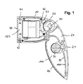
- Figure 1 shows a cross-sectional view of the lamp according to the invention with a fixed to a wall or niche wall mounted mounting plate 40, the Cross-section is U-shaped and has a recess in its upper leg 41 and in its lower leg has a projection 42. Furthermore a serving as a base part housing 10 is provided in his from the Wing profile 20 remote end portion a projection 11 in the upper region and a recess 12 in the lower region, by means of which the housing 10 in the mounting profile 40 can be inserted. Also a screw connection or any other suitable connection is possible.
- the housing 10 is as elongated substantially executed hollow component. In the case 10 are the electronic components of the lamp such as the electronic ballast, as well as the other electronic components preferably glued into the housing 10.
- the housing 10 In the area facing away from the mounting plate 40, the housing 10 a locking element 60, which consists of elastic plastic.
- the locking element 60 is executed part-circular and has a concave surface with Recesses 62 is provided.
- the locking element 60 is in a corresponding Recess of the housing 10 is inserted.
- the housing 10 further includes the bearing pin 90, which serves as a bearing for the wing profile 20 serves.
- the wing profile 20 has in its cross section a shape that the cross-sectional view A wing of an aircraft resembles. On its outside 21 The wing profile has a slightly curved surface, which is approximately at the top of the housing 10 is aligned, so that a harmonious transition between Housing 10 and wing profile 20 results.
- the wing profile 20 has a wall 95 with a highly polished surface 100, on which the light emanating from the light source 30 is reflected.
- an acrylic cover 70 is provided which makes contact with the hot Illuminant 30 prevents. This can be attached by a simple clip technique and allows an easy lamp replacement.
- the wing profile 20 in its cross-sectional view a tapered end on.
- a latching projection 50 is provided, the integral part of the Wing profile 20 is.
- the locking projection 50 is in the different recesses 62 of the locking element 60 inserted, so that preferred pivotal positions of the airfoil 20 relative to the housing 10 result.
- four locking positions which by a pivot angle of 15 ° are spaced.
- the mounting plate 40, the wing profile 20 and the housing 10 may be made be made of anodized aluminum.
- the cover 70 is made of transparent acrylic glass and has a disassembly / positioning aid (Handle nose) for easy disassembly when changing bulbs on.
- Both the wing profile 20 and the housing 10 are through in the end regions attachable cover caps 110, 120 lockable.
- the cover 110 of the airfoil 20 preferably made of a transparent material, for example made of polycarbonate.
- the covers 110, 120 can also consist of any other material, eg. B. aluminum, opaque Plastic etc.
- the cover 120 of the housing 10 is preferably not made transparent material, for example made of aluminum gray plastic.
- one or more latching elements are provided, which depends in particular on the length of the luminaire.
- the latching projection arranged on the bearing bush is or forms part of.
- the luminaire according to the invention can in principle also with a spring element with plain bearing bush, with a friction element with plain bearing bush or Also with a motor drive (eg 12V motor) or driven by a gear or be pivoted.
- a motor drive eg 12V motor
- FIG. 2 shows a further embodiment of the luminaire according to the invention.
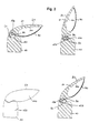
- the locking projection 50 is not in recesses of a locking element here runs, but is designed as a friction element that on a corresponding Counter surface 150 of the housing 10 runs and the pivoting movement of the sash profile 20 opposes a resistance.
- the locking projection 50 as a spring element executed, which has a permanent force on the part-circular tread 150 of the housing 10 exerts.
- FIG. 2 shows the wing profile 20 in different pivoting angles.
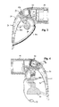
- FIG. 3 shows a further embodiment of the luminaire according to the invention.
- the illuminant 30 is located on the wing profile 20.
- the wing profile 20 with acrylic cover 70 is on its underside at this Embodiment designed more bulging.
- the acrylic glass cover 70 is removable.
- a recess having locking element 60 is provided, which is arranged on the housing 10 is. Placed against the latching element 60 are pivotally Locking projections 50 which engage in the latching element 60, wherein due to the Plurality of the locking projections 50 different pivoting angles can be realized.
- the locking element in turn as Run ahead and engages in corresponding recesses, the with the wing profile 20 in communication.
- FIG. 4 differs from FIG. 3 essentially in that as light source no fluorescent tube but one or more halogen spots used become. In this case, no cover, but a shock protection 32 is provided.
- FIG. 5 shows a cross-sectional view of an embodiment of the luminaire the housing 10 arranged locking element 60 and in the end region of the airfoil 20 arranged latching projection 50.
- the lamp 30 is in this embodiment also arranged on the wing profile, but without using a Cover.
- the housing 10 is attached to the fastening profile 40.
- FIG. 6 shows an exemplary embodiment in which the luminous means 30 is characterized by a semicircular Acrylic cover 70 is covered.
- the acrylic cover 70 has in their End recesses on, in the projections on the inside of the Wing profile 20 engage.
- the luminaire holding area is also of the Profile 20 detachable.
- FIG. 7 shows a further embodiment of the invention Lamp.
- no recesses exhibiting locking element is provided but a sliding surface 150, on which the resiliently executed locking projection 50th runs and a force on the sliding surface 150 exerts.
- the sash profile 20 steplessly lockable or adjustable in different positions.
- Figure 8 shows an embodiment of the luminaire according to the invention with strongly bulging Cover 70.
- the bearing pin 90 on the wing profile 20 rotatable is stored, as shown in Figure 8 can be seen on the housing 10 via.
- FIG. 9 shows a cross-sectional representation of the invention Luminaire with a substantially triangular housing 10, in the corner area the bearing pin 90 is arranged for pivotally receiving the wing profile 20 is.
- FIG. 10 shows a further embodiment of the present invention. This differs from the previously illustrated embodiments in that the illuminant 30 is arranged on the housing 10 and not on the wing profile 20 is. In this case, the wing profile 20 has essentially the task create diffused light that is glare-free and can be regulated.
- the wing profile 20 is on the locking projection 50 and the locking element 60 in stages adjustable. It has on its inside the polished surface 100, the serves to reflect the light emanating from the illuminant 30.
- the polished Surface 100 is on a wall 96 which is detachable with the profile 20 in FIG Connection stands. As a comparison of Figures 1 and 10 shows, the wall can 96, which acts as a reflector, are locked at the same attachment points, like the acrylic cover 70, so that the wing profile 20 can be used for cases, in which the luminous means 30 is arranged on the profile 20 or on the housing 10 is.
- FIG. 11 shows a further embodiment in which the luminous means 30 in the Housing 10 is arranged. Furthermore, a cover 160 is provided, by the contact with the lamp 30 is prevented.
- the sash profile 20 is relatively simple in this case. It has the curved outer surface 21 and a curved mirror-polished inside 100, the is located on the wall 96 and which serves as a reflector. Like a comparison of Figures 5 and 11 shows, the wall 96 by a holder for the lamp 30 be replaced. For this purpose, it is provided that the wall 96 or the holder detachably connected to the wing profile 20 in connection.
- FIG. 12 shows the luminaire according to FIG. 11 with a fluorescent tube as the luminous means 30th
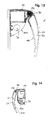
- FIG. 14 shows an embodiment in which the lighting means is also shown 30 is disposed behind a cover 160 on the housing 10, wherein the Housing 10 slightly different in shape from that of FIG. 13.
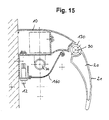
- FIG. 15 shows an embodiment with one in the direction of the wing profile 20 preferred housing 10 and also preferred cover 160. From Fig. Furthermore, the switch 12 arranged at the bottom of the housing 10 can be seen.
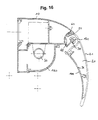
- FIG. 16 also shows an embodiment with an advanced housing 10, in FIG the lighting means 30 is arranged behind the cover 160. Further shown is the locking element 60 with the recesses 62 disposed therein as well the locking projection 50. Notwithstanding the embodiment of FIG. 1 is the locking element 60 not by a to be connected to the housing 10 plastic part formed, but by the the wing profile 20 facing the concave side of the housing 10. In this are recesses 62, in which the locking projection 50 engages. To a relative movement between locking projection 50 and locking element To enable 60, which required for an adjustment of the airfoil 20 is the locking projection 50 or the adjacent, this supporting end portion the profile 20 elastic or resilient executed.
- Reference numeral 96 denotes the insertable by a clip connection wall which the inner wall of the Wing profile 20 forms and is highly polished on the outside.
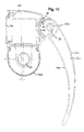
- FIG. 17 shows a further embodiment in which the luminous means 30 is disposed in the housing 10 and a substantially semicircular Abdekkung 160 has.
- the locking element 60 is shown hatched and is replaced by a part-circular elastic plastic part formed in a corresponding recess of the housing 10 is inserted.
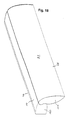
- FIG. 18 shows a perspective view of the luminaire according to the invention and illustrates that in a preferred embodiment of the invention, the housing 10 is designed as an elongated component. This points to his to the sash profile 20 directed side on a concave surface into which a convex end the sash profile 20 engages.
- the housing 10 and the wing profile 20 have about the same length.
- the housing 10 and the wing profile 20 is substantially independent from the pivotal position of the wing profile 20 with each other aligned surfaces have, as is apparent from Figure 18.
- the mounting profile 40 which is easy to install the lamp allows.
- the fastening profile 40 is provided with a wall, niche wall, a board, a cheek, a wall unit, etc. connected, preferably screwed.
- the airfoil 20 has a tapered end portion and one spaced therefrom convex, part-circular end region on. Both the outside 21 as well as the inside of the wing profile 20 are convex and give the Wing profile a cross-sectional profile similar to that of an aircraft wing.
- the wing profile 20 has a cover 110, which is transparent in contrast to the outside 21.
- a corresponding Cover is located on the other end of the wing profile 20th
- the housing is also provided with a cover 120 which may be plastic or plastic Metal part is executed and preferably has the same color as that Housing 10.
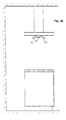
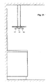
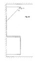
- FIGS. 19 to 32 show different arrangement possibilities of the invention Lamp.
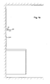
- Figure 19 shows the arrangement of the lamp on a niche wall 200 with wing profile 20, which is arranged so that the wing profile 20 in the pivoted state in an area below the housing extends.
- FIG. 20 shows the illustration according to FIG. 19 with the luminaire rotated by 180 °, the serves as a ceiling washer.
- the wing profile 20 to the Swinging niche wall is located, the profile 20 extends in one area above the housing 10.
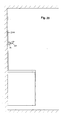
- FIG. 21 shows the luminaire according to the invention in an orientation according to FIG. 19 in the upper end region of the niche wall 200.
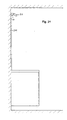
- FIG. 22 shows the luminaire according to the invention in an orientation according to FIG. 19 on the underside of a shelf or top cabinet.
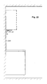
- FIG. 23 shows the luminaire in an orientation according to FIG. 19 in a wall unit. Accordingly, the luminaire serves as interior lighting.
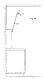
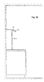
- FIG. 25 shows the luminaire according to the invention in an orientation according to FIG. 19 in the upper end region of a vertical support element 220.
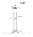
- FIG. 27 shows a floor lamp corresponding in principle to FIG. 26 with a housing 10 with two wing profiles 20 arranged thereon.
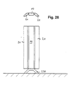
- Figure 28 shows a corresponding embodiment with wing profiles 20, the inner sides in the swung out state point in the same direction and each other to be moved.
- FIG. 29 shows an arrangement of the wing profiles according to FIG. 28, in which the lamp as a combination of two lights on a ceiling or according to figure 30 on an extractor hood or according to Figure 31 on any support can be arranged, which is attached to the ceiling.
- the arrangement of the bulbs towards the ceiling is possible.
- the light is used in this case as a ceiling washer.
- FIG. 32 shows the luminaire according to the invention finally in the front region of a Hood.
- the lamp according to the invention with a Switching element may be provided, wherein the wing profile itself as a switch for the Switching on or off the light can serve, or as a safety circuit in End position to excessive heat radiation, for example, on the niche rear wall to avoid.
- the surface of the sash profile can be smooth or textured outside be, z. B. also be provided with longitudinal ribs or longitudinal grooves.
- the inside of the Wing profile is preferably highly polished in Section Schl.ten, so that this area the task of a reflector takes over.
- the luminaire according to the invention is suitable for different applications Accordingly, it is designed and suitable as part of a modular concept.
Landscapes
- Engineering & Computer Science (AREA)
- General Engineering & Computer Science (AREA)
- Mechanical Engineering (AREA)
- Arrangement Of Elements, Cooling, Sealing, Or The Like Of Lighting Devices (AREA)
- Non-Portable Lighting Devices Or Systems Thereof (AREA)
- Fastening Of Light Sources Or Lamp Holders (AREA)
Applications Claiming Priority (2)
| Application Number | Priority Date | Filing Date | Title |
|---|---|---|---|
| DE10343533A DE10343533B4 (de) | 2003-09-19 | 2003-09-19 | Leuchte |
| DE10343533 | 2003-09-19 |
Publications (3)
| Publication Number | Publication Date |
|---|---|
| EP1517080A2 true EP1517080A2 (fr) | 2005-03-23 |
| EP1517080A3 EP1517080A3 (fr) | 2005-11-16 |
| EP1517080B1 EP1517080B1 (fr) | 2008-04-16 |
Family
ID=34177851
Family Applications (1)
| Application Number | Title | Priority Date | Filing Date |
|---|---|---|---|
| EP04021952A Expired - Lifetime EP1517080B1 (fr) | 2003-09-19 | 2004-09-15 | Luminaire |
Country Status (2)
| Country | Link |
|---|---|
| EP (1) | EP1517080B1 (fr) |
| DE (2) | DE10343533B4 (fr) |
Cited By (4)
| Publication number | Priority date | Publication date | Assignee | Title |
|---|---|---|---|---|
| EP2314929A3 (fr) * | 2009-10-23 | 2012-02-15 | BSH Bosch und Siemens Hausgeräte GmbH | Dispositif d'éclairage pour une surface de travail de cuisine et élément de cuisine doté d'une surface de travail de cuisine et d'au moins un dispositif d'éclairage |
| WO2013020841A1 (fr) * | 2011-08-11 | 2013-02-14 | Hella Kgaa Hueck & Co. | Appareil d'éclairage extérieur |
| WO2017211579A1 (fr) * | 2016-06-09 | 2017-12-14 | Philips Lighting Holding B.V. | Dispositif d'éclairage |
| EP2999920B1 (fr) | 2012-05-15 | 2018-10-03 | Musco Corporation | Appareil, procédé et système pour étapes de visée et d'interruption indépendantes dans l'éclairage d'une zone cible |
Families Citing this family (9)
| Publication number | Priority date | Publication date | Assignee | Title |
|---|---|---|---|---|
| DE202005010313U1 (de) * | 2005-06-30 | 2006-11-23 | Ilt Gmbh International Lighting Technologies | Stehleuchte mit Leuchtenkopf |
| DE102005031173B4 (de) * | 2005-07-04 | 2008-04-30 | Siteco Beleuchtungstechnik Gmbh | Leuchte mit Schwenkvorrichtung |
| DE102006041582A1 (de) * | 2006-09-05 | 2008-03-06 | BSH Bosch und Siemens Hausgeräte GmbH | Dunstabzugshaube |
| DE102010004352B4 (de) * | 2010-01-06 | 2016-09-08 | Teka Industrial S.A. | Küchenanordnung |
| DE102010006330A1 (de) * | 2010-01-29 | 2011-08-04 | GRAH Automotive d.o.o. | Mastaufsatzstück zur Befestigung eines Leuchtenkörpers an einem Leuchtenmast |
| DE102010040509A1 (de) * | 2010-09-09 | 2012-03-15 | BSH Bosch und Siemens Hausgeräte GmbH | Dunstabzugshaube |
| DE102012205237B4 (de) * | 2012-03-30 | 2019-11-28 | Andreas Hierzer | Leuchte zur Verwendung in einer Beleuchtungsanordnung |
| DE102013203103B4 (de) * | 2013-02-26 | 2018-05-09 | Osram Gmbh | Befestigungselement für eine Leuchtvorrichtung |
| DE102017101784A1 (de) | 2017-01-30 | 2018-08-02 | Osram Gmbh | Variabel einstellbares Schnellbefestigungssystem für Leuchten auf Mastflansche |
Family Cites Families (8)
| Publication number | Priority date | Publication date | Assignee | Title |
|---|---|---|---|---|
| US2740885A (en) * | 1951-06-25 | 1956-04-03 | A L Smith Iron Company | Adjustable fluorescent light fixture |
| DE7719975U1 (de) * | 1977-06-25 | 1977-10-13 | Luederitz, Willi, Dipl.-Ing., 4990 Luebbecke | Wandleuchte, insbesondere fuer krankenzimmer |
| DE4303185A1 (en) * | 1992-03-17 | 1993-09-23 | Zumtobel Licht | Hinged holder e.g. for wall- or ceiling-mounted lamp - Has bracket for lamp which can tilt through plus or minus 10 deg on parallel ribs with attachment screws limiting movement |
| US5564815A (en) * | 1994-06-29 | 1996-10-15 | Lightron Of Cornwall Incorporated | Adjustable light fixture |
| DE29503526U1 (de) * | 1995-03-03 | 1995-05-04 | Jokey Plastik Sohland GmbH, 02689 Sohland | Leuchtenträger, insbesondere für Einbauleuchten |
| DE19917283A1 (de) * | 1999-04-17 | 2000-10-19 | Licona Leuchten Gmbh | Leuchte mit einem rohrförmigen Basiskörper |
| DE10037081A1 (de) * | 1999-07-27 | 2001-03-15 | Steffen Ritter | Leuchte mit schwenkbar gelagertem Reflektorträger |
| DE10321282B4 (de) * | 2003-05-13 | 2010-11-25 | Trilux Gmbh & Co. Kg | Wandleuchte |
-
2003
- 2003-09-19 DE DE10343533A patent/DE10343533B4/de not_active Expired - Fee Related
-
2004
- 2004-09-15 EP EP04021952A patent/EP1517080B1/fr not_active Expired - Lifetime
- 2004-09-15 DE DE502004006825T patent/DE502004006825D1/de not_active Expired - Lifetime
Cited By (7)
| Publication number | Priority date | Publication date | Assignee | Title |
|---|---|---|---|---|
| EP2314929A3 (fr) * | 2009-10-23 | 2012-02-15 | BSH Bosch und Siemens Hausgeräte GmbH | Dispositif d'éclairage pour une surface de travail de cuisine et élément de cuisine doté d'une surface de travail de cuisine et d'au moins un dispositif d'éclairage |
| WO2013020841A1 (fr) * | 2011-08-11 | 2013-02-14 | Hella Kgaa Hueck & Co. | Appareil d'éclairage extérieur |
| CN103732978A (zh) * | 2011-08-11 | 2014-04-16 | 黑拉许克联合股份有限公司 | 室外照明灯 |
| CN103732978B (zh) * | 2011-08-11 | 2016-04-13 | 黑拉许克联合股份有限公司 | 室外照明灯 |
| EP2999920B1 (fr) | 2012-05-15 | 2018-10-03 | Musco Corporation | Appareil, procédé et système pour étapes de visée et d'interruption indépendantes dans l'éclairage d'une zone cible |
| WO2017211579A1 (fr) * | 2016-06-09 | 2017-12-14 | Philips Lighting Holding B.V. | Dispositif d'éclairage |
| US11149925B2 (en) | 2016-06-09 | 2021-10-19 | Signify Holding B.V. | Lighting device including adjustable cover |
Also Published As
| Publication number | Publication date |
|---|---|
| DE502004006825D1 (de) | 2008-05-29 |
| EP1517080B1 (fr) | 2008-04-16 |
| EP1517080A3 (fr) | 2005-11-16 |
| DE10343533A1 (de) | 2005-05-04 |
| DE10343533B4 (de) | 2007-08-09 |
Similar Documents
| Publication | Publication Date | Title |
|---|---|---|
| EP0898686B2 (fr) | Systeme d'eclairage muni d'un corps de base servant de support pour au moins une lampe | |
| EP1517080B1 (fr) | Luminaire | |
| DE102009007308A1 (de) | Anbau- bzw. Wandleuchte | |
| EP2071227A1 (fr) | Luminaire pour mur et/ou plafond | |
| DE102010060218A1 (de) | Beleuchtungsanordnung zur Beleuchtung einer Arbeitsplatte | |
| EP1537357B1 (fr) | Element de cuisine equipee | |
| DE10310330A1 (de) | Kältegerät mit Innenbeleuchtung | |
| EP1495258A2 (fr) | Luminaire plat | |
| DE202012100901U1 (de) | Einbauleuchte | |
| EP1035369B1 (fr) | Système d'éclairage | |
| DE202010001579U1 (de) | Beleuchtungsvorrichtung für ein bewegliches Möbelelement sowie Möbelelement | |
| DE2812090A1 (de) | Leuchte fuer reflektorlampen | |
| DE102014000558B3 (de) | Stehleuchte mit bifunktionalem Kopf | |
| EP2314929A2 (fr) | Dispositif d'éclairage pour une surface de travail de cuisine et élément de cuisine doté d'une surface de travail de cuisine et d'au moins un dispositif d'éclairage | |
| DE202022106912U1 (de) | Möbel | |
| DE102008018128B4 (de) | Schrankmöbel | |
| DE102007056403A1 (de) | Beleuchtungsanordnung | |
| DE10220958B4 (de) | Anbauleuchte | |
| DE29503526U1 (de) | Leuchtenträger, insbesondere für Einbauleuchten | |
| EP1145663B1 (fr) | Miroir de courtoisie | |
| EP4660519A1 (fr) | Luminaire comprenant un guide de lumière et un ensemble de diodes électroluminescentes et élément de meuble le comprenant | |
| DE202007014889U1 (de) | Badezimmerschrank | |
| WO2011020915A1 (fr) | Unité d'éclairage pouvant être fixée sans outil | |
| DE202009018096U1 (de) | Möbelstück mit einem Korpus und einer Beleuchtungseinrichtung | |
| DE20122084U1 (de) | Griffelement, insbesondere für Möbel |
Legal Events
| Date | Code | Title | Description |
|---|---|---|---|
| PUAI | Public reference made under article 153(3) epc to a published international application that has entered the european phase |
Free format text: ORIGINAL CODE: 0009012 |
|
| AK | Designated contracting states |
Kind code of ref document: A2 Designated state(s): AT BE BG CH CY CZ DE DK EE ES FI FR GB GR HU IE IT LI LU MC NL PL PT RO SE SI SK TR |
|
| AX | Request for extension of the european patent |
Extension state: AL HR LT LV MK |
|
| PUAL | Search report despatched |
Free format text: ORIGINAL CODE: 0009013 |
|
| AK | Designated contracting states |
Kind code of ref document: A3 Designated state(s): AT BE BG CH CY CZ DE DK EE ES FI FR GB GR HU IE IT LI LU MC NL PL PT RO SE SI SK TR |
|
| AX | Request for extension of the european patent |
Extension state: AL HR LT LV MK |
|
| 17P | Request for examination filed |
Effective date: 20060207 |
|
| AKX | Designation fees paid |
Designated state(s): CH DE FR IT LI |
|
| 17Q | First examination report despatched |
Effective date: 20060411 |
|
| GRAP | Despatch of communication of intention to grant a patent |
Free format text: ORIGINAL CODE: EPIDOSNIGR1 |
|
| GRAS | Grant fee paid |
Free format text: ORIGINAL CODE: EPIDOSNIGR3 |
|
| GRAA | (expected) grant |
Free format text: ORIGINAL CODE: 0009210 |
|
| AK | Designated contracting states |
Kind code of ref document: B1 Designated state(s): CH DE FR IT LI |
|
| REG | Reference to a national code |
Ref country code: CH Ref legal event code: NV Representative=s name: BOVARD AG PATENTANWAELTE Ref country code: CH Ref legal event code: EP |
|
| REF | Corresponds to: |
Ref document number: 502004006825 Country of ref document: DE Date of ref document: 20080529 Kind code of ref document: P |
|
| ET | Fr: translation filed | ||
| PLBE | No opposition filed within time limit |
Free format text: ORIGINAL CODE: 0009261 |
|
| STAA | Information on the status of an ep patent application or granted ep patent |
Free format text: STATUS: NO OPPOSITION FILED WITHIN TIME LIMIT |
|
| 26N | No opposition filed |
Effective date: 20090119 |
|
| PGFP | Annual fee paid to national office [announced via postgrant information from national office to epo] |
Ref country code: CH Payment date: 20090923 Year of fee payment: 6 |
|
| REG | Reference to a national code |
Ref country code: CH Ref legal event code: PFA Owner name: BULTHAUP GMBH & CO KG Free format text: BULTHAUP GMBH & CO KG#WERKSTRASSE 6#84155 BODENKIRCHEN (DE) -TRANSFER TO- BULTHAUP GMBH & CO KG#WERKSTRASSE 6#84155 BODENKIRCHEN (DE) |
|
| REG | Reference to a national code |
Ref country code: CH Ref legal event code: PL |
|
| REG | Reference to a national code |
Ref country code: FR Ref legal event code: ST Effective date: 20110531 |
|
| PG25 | Lapsed in a contracting state [announced via postgrant information from national office to epo] |
Ref country code: CH Free format text: LAPSE BECAUSE OF NON-PAYMENT OF DUE FEES Effective date: 20100930 Ref country code: LI Free format text: LAPSE BECAUSE OF NON-PAYMENT OF DUE FEES Effective date: 20100930 Ref country code: FR Free format text: LAPSE BECAUSE OF NON-PAYMENT OF DUE FEES Effective date: 20100930 |
|
| PGFP | Annual fee paid to national office [announced via postgrant information from national office to epo] |
Ref country code: FR Payment date: 20091005 Year of fee payment: 6 |
|
| REG | Reference to a national code |
Ref country code: DE Ref legal event code: R082 Ref document number: 502004006825 Country of ref document: DE Representative=s name: KLUNKER IP PATENTANWAELTE PARTG MBB, DE |
|
| PGFP | Annual fee paid to national office [announced via postgrant information from national office to epo] |
Ref country code: IT Payment date: 20220930 Year of fee payment: 19 Ref country code: DE Payment date: 20221114 Year of fee payment: 19 |
|
| REG | Reference to a national code |
Ref country code: DE Ref legal event code: R119 Ref document number: 502004006825 Country of ref document: DE |
|
| PG25 | Lapsed in a contracting state [announced via postgrant information from national office to epo] |
Ref country code: DE Free format text: LAPSE BECAUSE OF NON-PAYMENT OF DUE FEES Effective date: 20240403 |
|
| PG25 | Lapsed in a contracting state [announced via postgrant information from national office to epo] |
Ref country code: IT Free format text: LAPSE BECAUSE OF NON-PAYMENT OF DUE FEES Effective date: 20230915 |
|
| PG25 | Lapsed in a contracting state [announced via postgrant information from national office to epo] |
Ref country code: IT Free format text: LAPSE BECAUSE OF NON-PAYMENT OF DUE FEES Effective date: 20230915 |