EP1517090A2 - Elektroherd und Verfahren zur Regelung der Heizelemente - Google Patents
Elektroherd und Verfahren zur Regelung der Heizelemente Download PDFInfo
- Publication number
- EP1517090A2 EP1517090A2 EP04250608A EP04250608A EP1517090A2 EP 1517090 A2 EP1517090 A2 EP 1517090A2 EP 04250608 A EP04250608 A EP 04250608A EP 04250608 A EP04250608 A EP 04250608A EP 1517090 A2 EP1517090 A2 EP 1517090A2
- Authority
- EP
- European Patent Office
- Prior art keywords
- temperature
- power
- heaters
- periods
- cooking cavity
- Prior art date
- Legal status (The legal status is an assumption and is not a legal conclusion. Google has not performed a legal analysis and makes no representation as to the accuracy of the status listed.)
- Granted
Links
Images


Classifications
-
- F—MECHANICAL ENGINEERING; LIGHTING; HEATING; WEAPONS; BLASTING
- F24—HEATING; RANGES; VENTILATING
- F24C—DOMESTIC STOVES OR RANGES ; DETAILS OF DOMESTIC STOVES OR RANGES, OF GENERAL APPLICATION
- F24C7/00—Stoves or ranges heated by electric energy
- F24C7/04—Stoves or ranges heated by electric energy with heat radiated directly from the heating element
-
- F—MECHANICAL ENGINEERING; LIGHTING; HEATING; WEAPONS; BLASTING
- F24—HEATING; RANGES; VENTILATING
- F24C—DOMESTIC STOVES OR RANGES ; DETAILS OF DOMESTIC STOVES OR RANGES, OF GENERAL APPLICATION
- F24C7/00—Stoves or ranges heated by electric energy
- F24C7/08—Arrangement or mounting of control or safety devices
- F24C7/087—Arrangement or mounting of control or safety devices of electric circuits regulating heat
Definitions
- the present invention relates, in general, to an electric cooking apparatus and method of controlling heaters thereof and, more particularly but not exclusively, to an electric cooking apparatus and method of controlling heaters thereof, which are capable of uniformly maintaining a temperature of a cooking cavity by cutting off and supplying power to the heaters according to periods preset in view of a temperature of the heaters.
- an electric cooking apparatus is provided with electric heaters therein which cook food by heating the food with heat emitted from the electric heaters.
- the electric cooking apparatus typically includes a cooking cavity to accommodate food, electric heaters to supply heat to the cooking cavity, and a temperature sensor to detect a temperature of the cooking cavity.
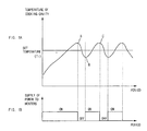
- an X-axis thereof represents periods, a Y-axis thereof indicates whether power is supplied or not to the heaters.
- a supply of power to the heaters is indicated by ON, while a cutoff of power to the heaters is indicated by OFF.
- an X-axis thereof represents periods, and a Y-axis thereof represents temperatures of the cooking cavity depending on supplies and cutoffs of power to the heaters that are plotted on the lower graph of Figure 1.
- a cooking mode using the heaters it is determined whether the temperature of the cooking cavity input from the temperature sensor is higher or lower than a set temperature T1. If the temperature of the cooking cavity is lower than the set temperature T1, the heaters are turned on. Accordingly, the temperature of the cooking cavity increases by operation of the heaters. When the temperature of the cooking cavity increases higher than the set temperature T1 by a certain amount or more (for example, higher than the set temperature T1 by a temperature of +5°C) (see position A), the power to the heaters is cut off.
- the temperature of the cooking cavity slightly increases just after the cutoff of the power. Thereafter, the temperature of the cooking cavity decreases depending on an external temperature or an insulation state of the cooking cavity.
- the temperature of the cooking cavity decreases to less than the set temperature T1 by a certain amount or more (for example, lower than the set temperature T1 by a temperature of -5°C) (see position B)
- power is supplied to the heaters again to increase the temperature of the cooking cavity.
- the temperature of the cooking cavity increases again.
- the power to the heaters is cut off to maintain the temperature of the cooking cavity at a temperature near the set temperature T1. The above-described process is repeated during an overall cooking period.
- a power-ON period is longer than a power-OFF period (for example, the power-ON period is twice the power-OFF period), and the power-ON period and the power-OFF period are set in minutes. Accordingly, when the temperature of the heaters is considerably decreased after the power to the heaters had been cut off and several minutes have elapsed, power is supplied to the heaters again.
- the conventional electric cooking apparatus is problematic in that excessive power is consumed to resume a normal operation of the heaters because power is supplied to the heater again after the supply of power to the heater has been cut off and a considerable period has elapsed. Furthermore, the conventional electric cooking apparatus is problematic in that quality of cooking is reduced because the temperature of the cooking cavity is not accurately controlled but roughly controlled, and a cooking period increases because the heat is not uniformly applied to the food.
- an electric cooking apparatus and method of controlling heaters thereof in which the heaters operate according to power-ON periods and power-OFF periods set in view of a temperature of the heaters, consumption of unnecessary power is reduced, and variations of heat supplied to a cooking cavity are decreased, thus improving quality of cooking and shortening overall cooking periods.
- a method of controlling heaters of an electric cooking apparatus including detecting a temperature of a cooking cavity, and operating the heater according to preset power-ON and power-OFF periods to allow the heaters to be maintained at a temperature within a range around a certain temperature when the temperature of the cooking cavity reaches a set temperature.
- a method of controlling heaters of an electric cooking apparatus comprising: detecting a temperature of a cooking cavity; and operating the heater according to preset power-ON and power-OFF periods to allow the heaters to be maintained at a temperature within a range around a certain temperature when the temperature of the cooking cavity reaches a set temperature.
- a method of controlling heaters of an electric cooking apparatus comprising: detecting a temperature of a cooking cavity; and performing a temperature increasing mode in which a supply of power and a cut-off of power to the heaters are alternately performed while increasing a ratio of a power-OFF period to a power-ON period if the detected temperature of the cooking cavity is not equal to a set temperature, and performing a temperature maintaining mode in which the heaters are operated according to preset power-ON and power-OFF periods to be maintained at a temperature within a certain range around a certain temperature if the detected temperature of the cooking cavity reaches the set temperature.
- an electric cooking apparatus comprising: heaters supplying heat to a cooking cavity; and a control unit controlling the heaters to be operated according to preset power-ON periods and power-OFF periods so as to allow the heaters to be maintained at a temperature within a range around a certain temperature when the temperature of the cooking cavity reaches a set temperature.
- the electric oven to which the present invention is applied includes a body 10, and a cooking cavity 11 provided in the body 10.
- An upper heater 12 and a lower heater 13 are installed in upper and lower portions of the cooking cavity 11 to be spaced apart from top and bottom of the cooking cavity 11 by certain intervals, respectively.
- a first end of each of the heaters 12 and 13 is fastened to a back wall of the cooking cavity 11, while a second end thereof is fastened using a fastening member fitted around the second end.
- a temperature sensor 14 is embedded in a sidewall of the cooking cavity 11 to detect a temperature of the cooking cavity 11.
- Two food supports 15 are provided between the upper and lower heaters 12 and 13 to hold food.
- a display unit 16 provided with a plurality of lamps to display operational status of the electric oven, and an input unit 17 used to input operation signals so as to operate the electric oven are disposed on an upper portion of a front of the body 10.
- the heat controlling method uses a phenomenon, in which a surface temperature of the heaters 12 and 13 does not decrease immediately but is maintained for a certain period (approximately two to four seconds) even though power is cut off.
- power required to increase the temperature of the heaters 12 and 13 may be reduced by supplying power within a period in which the heaters 12 and 13 are maintained at a surface temperature achieved when the power to the heaters 12 and 13 had been cut off, rather than supplying power once again after a considerably long period has elapsed since power had been cut off.
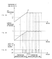
- an X-axis thereof represents periods, while a Y-axis thereof indicates whether power is supplied to heaters or power to the heaters is cut off.
- a supply of power to the heaters is indicated by ON, while a cutoff power to the heaters is indicated by OFF.
- an X-axis thereof represents periods, while a Y-axis thereof represents surface temperatures of the heaters.
- an X-axis thereof represents periods, while a Y-axis thereof represents temperature of the cooking cavity.
- an overall range may be divided into a temperature increasing mode M1 and a temperature maintaining mode M2.
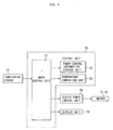
- a temperature comparison unit 23 provided in a control unit 20.
- the temperature comparison unit 23 compares a set temperature T2 with the temperature of the cooking cavity 11 detected by the temperature sensor 14. If the set temperature T2 is equal to the detected temperature of the cooking cavity 11, a main control 21 performs the temperature maintaining mode M2. If the set temperature T2 is not equal to the detected temperature of the cooking cavity 11, the main control 21 performs a temperature correcting mode.
- the temperature correcting mode is a mode that is performed when the set temperature T2 is different from the temperature of the cooking cavity.
- the temperature correcting mode may be divided into a temperature decreasing mode performed to decrease the temperature of the cooking cavity because the temperature of the cooking cavity is higher than the set temperature T2, and the temperature increasing mode M1 performed to increase the temperature of the cooking cavity because the temperature of the cooking cavity is lower than the set temperature T2.
- a heater power control unit 24 cuts off power from the heaters until the temperature of the cooking cavity reaches the set temperature T2.
- the temperature increasing mode the temperature of the cooking cavity is detected. If the temperature of the cooking cavity is lower than half of the set temperature T2, the heater power control unit 24 controls power to be continuously supplied to the heaters. In contrast, if the temperature of the cooking cavity is equal to or higher than half of the set temperature T2 and is lower than the set temperature T2, the heater power control unit 24 controls power to be alternately supplied and cut off according to information about power-ON periods and power-OFF periods stored in a power control information storage unit 22, with each of the power-ON periods being longer than each of the power-OFF periods.
- the heater power control unit 24 decreases a ratio of the power-ON period and increases a ratio of the power-OFF period until the ratio of the power-ON period equals the ratio of the power-OFF period.
- the power-OFF period of the heaters is preferably set in a range in which the heaters 12 and 13 are maintained at a surface temperature achieved when power to the heaters 12 and 13 is cut off.
- the temperature increasing mode M1 ends.
- the supply of power and the cutoff of power to the heaters 12 and 13 may be alternately performed rather than continuously.
- the temperature maintaining mode M2 is a mode in which the surface temperature of the heater, achieved when the temperature of the cooking cavity detected by the temperature sensor 14 reaches the set temperature M2, is maintained within a certain range.
- the control unit 21 maintains the surface temperature of the heaters at this point.
- a control may be performed to maintain the surface temperature of the heaters achieved when the surface temperature of the heaters reaches the set temperature T2, but the surface temperature of the heaters may also be controlled using data on temperatures of the cooking cavity corresponding to surface temperatures of the heaters after setting and storing the data. That is, if the temperature of the cooking cavity reaches the setting temperature, the main control unit 21 selects a corresponding temperature from the data on the temperatures of the cooking cavity corresponding to the surface temperatures of the heaters and controls the heaters maintaining them at the selected temperature. When the temperature of the heaters is controlled using the data, an operation of changing the temperature of the heaters to coincide with the data on the temperature of the cooking cavity corresponding to the surface temperature of the heaters is required.
- the method of detecting a surface temperature of the heaters achieved when the temperature of the cooking cavity reaches the set temperature T1 and maintaining the temperature of the heaters may be used.
- the method of selecting a certain temperature from stored data and controlling the temperature of the heaters may also be used.
- the heater power control unit 24 operates the power-ON periods Tb and the power-OFF periods Ta of the heaters, preset and stored in the power control information storage unit 22.
- each of the power-OFF periods Ta is preferably set within a range in which the surface temperature of the heaters does not considerably decrease, and the power-ON period Tb is preferably set to half of the power-OFF period Ta.
- the power-OFF period Ta is set to several seconds rather than several minutes as in a conventional scheme.
- the power-OFF period Ta may be set in view of an extent to which the surface temperature of the heaters decrease. As the power-OFF period Ta is increased, more power is consumed to increase the temperature of the heaters.
- the power-ON period Tb and the power-OFF period Ta stored in the power control information storage unit 22 are set to three and six seconds, respectively, an operation of supplying power to the heaters for three seconds and cutting off the power for six seconds is repeated.
- the surface temperature of the heaters rapidly increases, while, in the power-OFF period Ta, the surface temperature of the heaters slowly decreases. Even though the power-ON period is shorter than the power-OFF period, the surface temperature of the heaters is maintained without considerable change, thus maintaining the temperature of the cooking cavity at the set temperature.
- the temperature of the cooking cavity may be increased in the temperature increasing mode and maintained in the temperature maintaining mode by controlling an interval between the power-ON period Tb and the power-OFF period Ta.
- Power required to increase the temperature of the heaters again would be saved by supplying power to the heaters while maintaining the surface temperature of the heaters within a certain range after cutting off power from the heaters.
- the temperature sensor 14 detects a temperature of the cooking cavity in operation 32.
- the detected temperature of the cooking cavity is input to the temperature comparison unit 23 through the main control unit 21.
- the temperature comparison unit 23 determines whether the detected temperature of the cooking chamber is equal to the set temperature T2 in operation 34.
- the temperature maintaining mode is performed maintaining the heaters at a surface temperature in operation 36. That is, the heater power control unit 24 operates the heaters according to power-ON periods and power-OFF periods preset and input to the power control information storage unit 22 maintaining the temperature of the cooking cavity.
- the heater power control unit 24 cuts off power to the heaters by performing the temperature decreasing mode in operation 50.
- the temperature comparison unit 23 determines whether the temperature of the cooking cavity is lower than half of the set temperature T2 to perform the temperature increasing mode in operation 40. If the temperature of the cooking cavity is lower than half of the set temperature T2, the heater power control unit 24 continuously supplies power to the heaters. If the temperature of the cooking cavity is not lower than half of the set temperature T2, the heater power control unit 24 operates the heaters with the power-ON period set to ten seconds and the power-OFF period set to three seconds in operation 42. With a lapse of time, the power-ON period gradually decreases and the power-OFF period gradually increases in operation 44. In this case, an extent of the change may be appropriately set.
- the main control unit 21 determines whether the power-ON period is equal to the power-OFF period in operation 46. If the power-ON period is not equal to the power-OFF period, the process returns to operation 44, if the power-ON period is equal to the power-OFF period, it is determined whether the temperature of the cooking cavity reaches the set temperature T2 in operation 48. If the temperature of the cooking cavity does not reach the set temperature T2, the process repeats operation 48, if the temperature of the cooking cavity reaches the set temperature T2, the process performs the temperature maintaining mode in operation 36. After performing operation 36, the process ends.
- the present invention provides an electric cooking apparatus and method of controlling heaters thereof, in which a temperature of the heaters is utilized, thus improving a thermal efficiency with respect to power, and reducing variations of heat supplied to a cooking cavity, thus improving quality of cooking and shortening overall cooking periods.
Landscapes
- Engineering & Computer Science (AREA)
- Chemical & Material Sciences (AREA)
- Combustion & Propulsion (AREA)
- Mechanical Engineering (AREA)
- General Engineering & Computer Science (AREA)
- Electric Stoves And Ranges (AREA)
- Control Of Resistance Heating (AREA)
Priority Applications (1)
| Application Number | Priority Date | Filing Date | Title |
|---|---|---|---|
| EP09151255.8A EP2045532B1 (de) | 2003-09-09 | 2004-02-05 | Verfahren zur Regelung der Heizelemente eines Elektroherds |
Applications Claiming Priority (2)
| Application Number | Priority Date | Filing Date | Title |
|---|---|---|---|
| KR2003063012 | 2003-09-09 | ||
| KR1020030063012A KR100955485B1 (ko) | 2003-09-09 | 2003-09-09 | 전기조리장치 및 그 히터제어방법 |
Related Child Applications (1)
| Application Number | Title | Priority Date | Filing Date |
|---|---|---|---|
| EP09151255.8A Division EP2045532B1 (de) | 2003-09-09 | 2004-02-05 | Verfahren zur Regelung der Heizelemente eines Elektroherds |
Publications (3)
| Publication Number | Publication Date |
|---|---|
| EP1517090A2 true EP1517090A2 (de) | 2005-03-23 |
| EP1517090A3 EP1517090A3 (de) | 2006-02-15 |
| EP1517090B1 EP1517090B1 (de) | 2009-04-22 |
Family
ID=34192221
Family Applications (2)
| Application Number | Title | Priority Date | Filing Date |
|---|---|---|---|
| EP09151255.8A Expired - Lifetime EP2045532B1 (de) | 2003-09-09 | 2004-02-05 | Verfahren zur Regelung der Heizelemente eines Elektroherds |
| EP04250608A Expired - Lifetime EP1517090B1 (de) | 2003-09-09 | 2004-02-05 | Elektroherd und Verfahren zur Regelung der Heizelemente |
Family Applications Before (1)
| Application Number | Title | Priority Date | Filing Date |
|---|---|---|---|
| EP09151255.8A Expired - Lifetime EP2045532B1 (de) | 2003-09-09 | 2004-02-05 | Verfahren zur Regelung der Heizelemente eines Elektroherds |
Country Status (6)
| Country | Link |
|---|---|
| US (1) | US7053342B2 (de) |
| EP (2) | EP2045532B1 (de) |
| JP (1) | JP3874763B2 (de) |
| KR (1) | KR100955485B1 (de) |
| CN (1) | CN1291682C (de) |
| DE (1) | DE602004020718D1 (de) |
Families Citing this family (17)
| Publication number | Priority date | Publication date | Assignee | Title |
|---|---|---|---|---|
| KR100794825B1 (ko) * | 2006-12-28 | 2008-01-15 | 엘지전자 주식회사 | 오븐 및 오븐의 제어방법 |
| DE102007056714A1 (de) * | 2007-11-26 | 2009-05-28 | BSH Bosch und Siemens Hausgeräte GmbH | Verfahren zum Betrieb eines Gargeräts und Gargerät |
| WO2013059632A1 (en) * | 2011-10-19 | 2013-04-25 | John Rankin | Method for indirect food temperature measurement |
| US20130236614A1 (en) * | 2012-03-10 | 2013-09-12 | Hamilton Beach Brands, Inc. | Kitchen Appliance & Method of Using Same |
| CN102629114A (zh) * | 2012-04-24 | 2012-08-08 | 镇江智拓智能科技发展有限公司 | 一种智能烹饪控制方法及烹饪装置 |
| WO2016139246A1 (en) * | 2015-03-04 | 2016-09-09 | Arcelik Anonim Sirketi | A cooking device wherein the heater is controlled |
| CN105739559A (zh) * | 2016-05-11 | 2016-07-06 | 北京小焙科技有限公司 | 一种温度控制方法及系统 |
| CN106152195A (zh) * | 2016-06-23 | 2016-11-23 | 珠海格力电器股份有限公司 | 电磁炉的控制方法及装置 |
| US10721948B1 (en) * | 2017-02-08 | 2020-07-28 | Electrolux Home Products, Inc. | Air sous-vide |
| CN109143911B (zh) * | 2017-06-19 | 2022-02-01 | 佛山市顺德区美的电热电器制造有限公司 | 煮饭过程的吸水阶段中控制加热的方法和装置 |
| CN107314406B (zh) * | 2017-06-28 | 2019-06-18 | 浙江绍兴苏泊尔生活电器有限公司 | 电磁炉的控制方法 |
| JP6865388B2 (ja) * | 2017-07-26 | 2021-04-28 | パナソニックIpマネジメント株式会社 | 加熱調理器 |
| CN108594898B (zh) * | 2018-04-26 | 2021-07-23 | 广东美的厨房电器制造有限公司 | 烤箱温控方法、装置及计算机可读存储介质 |
| CN109124383A (zh) * | 2018-09-07 | 2019-01-04 | 广东美的厨房电器制造有限公司 | 控制方法、控制装置、烹饪设备和计算机可读存储介质 |
| CN110960106B (zh) * | 2018-09-28 | 2022-03-22 | 广东美的厨房电器制造有限公司 | 电烤箱控制系统、方法及电烤箱 |
| EP4019848B1 (de) | 2020-12-22 | 2024-05-15 | Electrolux Appliances Aktiebolag | Verfahren zum betreiben eines backofens |
| CN114010056B (zh) * | 2021-10-15 | 2022-10-28 | 杭州凤凰智能控制有限公司 | 一种电蒸箱蒸汽量及腔体温度场智能控制方法 |
Citations (1)
| Publication number | Priority date | Publication date | Assignee | Title |
|---|---|---|---|---|
| EP0866278A1 (de) | 1997-03-18 | 1998-09-23 | Bosch-Siemens HausgerÀ¤te GmbH | Verfahren zur Regelung thermischer Strecken und Heizeinrichtungen in Haushaltgeräten |
Family Cites Families (13)
| Publication number | Priority date | Publication date | Assignee | Title |
|---|---|---|---|---|
| US4088862A (en) * | 1976-04-08 | 1978-05-09 | Roper Corporation | Timer operated control circuit for a microwave oven |
| CA1147036A (en) * | 1978-09-26 | 1983-05-24 | Shigeru Kusunoki | Method of controlling heating in food heating apparatus including infrared detecting system |
| US4333519A (en) * | 1980-05-08 | 1982-06-08 | Doron Shafrir | Controller for air conditioning units, heating units and the like |
| US4947875A (en) * | 1988-09-08 | 1990-08-14 | R. J. Reynolds Tobacco Company | Flavor delivery articles utilizing electrical energy |
| JPH0417816A (ja) * | 1990-05-11 | 1992-01-22 | Matsushita Electric Ind Co Ltd | 電気ホットプレート |
| JPH04206184A (ja) * | 1990-11-29 | 1992-07-28 | Toshiba Corp | 加熱調理器 |
| DE4217749C2 (de) * | 1992-05-29 | 1996-11-21 | Miele & Cie | Verfahren zur Steuerung der Backmuffeltemperatur |
| JPH07229626A (ja) * | 1994-02-16 | 1995-08-29 | Sanyo Electric Co Ltd | 加熱調理装置における温度制御方法 |
| DE69620290T2 (de) * | 1995-05-19 | 2002-11-28 | Sharp K.K., Osaka | Tonerbildfixiervorrichtung für Bilderzeugungsgerät |
| DE19813550A1 (de) * | 1998-03-27 | 1999-09-30 | Ego Elektro Geraetebau Gmbh | Verfahren zum Betrieb eines Elektrowärmegerätes |
| US6337468B1 (en) * | 1998-07-14 | 2002-01-08 | General Electric Company | Rapid recovery oven control and method |
| US6140619A (en) | 1999-05-28 | 2000-10-31 | The Garland Group | Temperature control apparatus, method and memory medium for an oven |
| DE10132304B4 (de) * | 2001-07-06 | 2005-10-27 | BSH Bosch und Siemens Hausgeräte GmbH | Verfahren zum Betrieb eines Gargeräts |
-
2003
- 2003-09-09 KR KR1020030063012A patent/KR100955485B1/ko not_active Expired - Fee Related
-
2004
- 2004-02-05 DE DE602004020718T patent/DE602004020718D1/de not_active Expired - Lifetime
- 2004-02-05 EP EP09151255.8A patent/EP2045532B1/de not_active Expired - Lifetime
- 2004-02-05 CN CNB2004100053166A patent/CN1291682C/zh not_active Expired - Fee Related
- 2004-02-05 EP EP04250608A patent/EP1517090B1/de not_active Expired - Lifetime
- 2004-02-10 US US10/774,484 patent/US7053342B2/en not_active Expired - Lifetime
- 2004-03-25 JP JP2004090569A patent/JP3874763B2/ja not_active Expired - Fee Related
Patent Citations (1)
| Publication number | Priority date | Publication date | Assignee | Title |
|---|---|---|---|---|
| EP0866278A1 (de) | 1997-03-18 | 1998-09-23 | Bosch-Siemens HausgerÀ¤te GmbH | Verfahren zur Regelung thermischer Strecken und Heizeinrichtungen in Haushaltgeräten |
Also Published As
| Publication number | Publication date |
|---|---|
| EP2045532A3 (de) | 2010-09-08 |
| JP2005083737A (ja) | 2005-03-31 |
| JP3874763B2 (ja) | 2007-01-31 |
| KR20050026606A (ko) | 2005-03-15 |
| CN1593314A (zh) | 2005-03-16 |
| CN1291682C (zh) | 2006-12-27 |
| US20050051534A1 (en) | 2005-03-10 |
| US7053342B2 (en) | 2006-05-30 |
| EP2045532B1 (de) | 2015-11-25 |
| DE602004020718D1 (de) | 2009-06-04 |
| EP2045532A2 (de) | 2009-04-08 |
| EP1517090A3 (de) | 2006-02-15 |
| KR100955485B1 (ko) | 2010-04-30 |
| EP1517090B1 (de) | 2009-04-22 |
Similar Documents
| Publication | Publication Date | Title |
|---|---|---|
| EP1517090A2 (de) | Elektroherd und Verfahren zur Regelung der Heizelemente | |
| US5317130A (en) | Programmable load compensation method and apparatus for use in a food oven | |
| WO2015159923A1 (ja) | 調理器 | |
| US6906294B2 (en) | Composite cooking apparatus and method of controlling the same | |
| KR20170000915A (ko) | 전기 조리기 | |
| EP1392085A2 (de) | Kochvorrichtung versehen mit Heizelementen | |
| JP2003207255A (ja) | 冷蔵庫及びその制御方法 | |
| JP2009218050A (ja) | 誘導加熱調理器 | |
| KR101209599B1 (ko) | 오븐의 조리물 량에 따른 온도제어방법 | |
| JP2005130991A (ja) | 炊飯器 | |
| KR20000033160A (ko) | 전자김치독의 익힘정도 검출장치 및 그 검출방법 | |
| JP2005221086A (ja) | オーブントースター | |
| JP2001194008A (ja) | 電気温水器及びその運転方法 | |
| JP5598165B2 (ja) | 誘導加熱調理器 | |
| JP2011122776A (ja) | オーブントースター | |
| JP2003166776A (ja) | 冷蔵庫の制御装置 | |
| KR100857713B1 (ko) | 차량용 공기조화기의 보조 난방장치 및 그 제어방법 | |
| JP2005180838A (ja) | 加熱調理器 | |
| JPH03286960A (ja) | 貯湯式電気温水器 | |
| KR100999745B1 (ko) | 조리기기 제어방법 | |
| KR20090060496A (ko) | 오븐레인지의 보온 서랍 온도제어장치 및 방법 | |
| JP2008075930A (ja) | 加熱調理器 | |
| JP2003210328A (ja) | 電気湯沸かし器 | |
| KR20020034566A (ko) | 히터를 이용한 요리시 전원보상 방법 | |
| KR20050081662A (ko) | 조리용 오븐의 히터 제어 방법 |
Legal Events
| Date | Code | Title | Description |
|---|---|---|---|
| PUAI | Public reference made under article 153(3) epc to a published international application that has entered the european phase |
Free format text: ORIGINAL CODE: 0009012 |
|
| AK | Designated contracting states |
Kind code of ref document: A2 Designated state(s): AT BE BG CH CY CZ DE DK EE ES FI FR GB GR HU IE IT LI LU MC NL PT RO SE SI SK TR |
|
| AX | Request for extension of the european patent |
Extension state: AL LT LV MK |
|
| PUAL | Search report despatched |
Free format text: ORIGINAL CODE: 0009013 |
|
| AK | Designated contracting states |
Kind code of ref document: A3 Designated state(s): AT BE BG CH CY CZ DE DK EE ES FI FR GB GR HU IE IT LI LU MC NL PT RO SE SI SK TR |
|
| AX | Request for extension of the european patent |
Extension state: AL LT LV MK |
|
| 17P | Request for examination filed |
Effective date: 20060502 |
|
| AKX | Designation fees paid |
Designated state(s): DE FR GB |
|
| 17Q | First examination report despatched |
Effective date: 20080328 |
|
| GRAP | Despatch of communication of intention to grant a patent |
Free format text: ORIGINAL CODE: EPIDOSNIGR1 |
|
| GRAS | Grant fee paid |
Free format text: ORIGINAL CODE: EPIDOSNIGR3 |
|
| GRAA | (expected) grant |
Free format text: ORIGINAL CODE: 0009210 |
|
| AK | Designated contracting states |
Kind code of ref document: B1 Designated state(s): DE FR GB |
|
| REG | Reference to a national code |
Ref country code: GB Ref legal event code: FG4D |
|
| REF | Corresponds to: |
Ref document number: 602004020718 Country of ref document: DE Date of ref document: 20090604 Kind code of ref document: P |
|
| PLBE | No opposition filed within time limit |
Free format text: ORIGINAL CODE: 0009261 |
|
| STAA | Information on the status of an ep patent application or granted ep patent |
Free format text: STATUS: NO OPPOSITION FILED WITHIN TIME LIMIT |
|
| 26N | No opposition filed |
Effective date: 20100125 |
|
| REG | Reference to a national code |
Ref country code: FR Ref legal event code: PLFP Year of fee payment: 13 |
|
| REG | Reference to a national code |
Ref country code: FR Ref legal event code: PLFP Year of fee payment: 14 |
|
| PGFP | Annual fee paid to national office [announced via postgrant information from national office to epo] |
Ref country code: FR Payment date: 20170126 Year of fee payment: 14 |
|
| REG | Reference to a national code |
Ref country code: DE Ref legal event code: R082 Ref document number: 602004020718 Country of ref document: DE Representative=s name: WUNDERLICH & HEIM PATENTANWAELTE PARTNERSCHAFT, DE |
|
| REG | Reference to a national code |
Ref country code: FR Ref legal event code: ST Effective date: 20181031 |
|
| PG25 | Lapsed in a contracting state [announced via postgrant information from national office to epo] |
Ref country code: FR Free format text: LAPSE BECAUSE OF NON-PAYMENT OF DUE FEES Effective date: 20180228 |
|
| PGFP | Annual fee paid to national office [announced via postgrant information from national office to epo] |
Ref country code: GB Payment date: 20220121 Year of fee payment: 19 |
|
| PGFP | Annual fee paid to national office [announced via postgrant information from national office to epo] |
Ref country code: DE Payment date: 20230119 Year of fee payment: 20 |
|
| GBPC | Gb: european patent ceased through non-payment of renewal fee |
Effective date: 20230205 |
|
| PG25 | Lapsed in a contracting state [announced via postgrant information from national office to epo] |
Ref country code: GB Free format text: LAPSE BECAUSE OF NON-PAYMENT OF DUE FEES Effective date: 20230205 |
|
| PG25 | Lapsed in a contracting state [announced via postgrant information from national office to epo] |
Ref country code: GB Free format text: LAPSE BECAUSE OF NON-PAYMENT OF DUE FEES Effective date: 20230205 |
|
| REG | Reference to a national code |
Ref country code: DE Ref legal event code: R071 Ref document number: 602004020718 Country of ref document: DE |