EP1517092A1 - Ofen mit überhitztem Dampf und zugehöriges Steuerverfahren - Google Patents
Ofen mit überhitztem Dampf und zugehöriges Steuerverfahren Download PDFInfo
- Publication number
- EP1517092A1 EP1517092A1 EP04252952A EP04252952A EP1517092A1 EP 1517092 A1 EP1517092 A1 EP 1517092A1 EP 04252952 A EP04252952 A EP 04252952A EP 04252952 A EP04252952 A EP 04252952A EP 1517092 A1 EP1517092 A1 EP 1517092A1
- Authority
- EP
- European Patent Office
- Prior art keywords
- steam
- cooking cavity
- overheated steam
- water
- overheated
- Prior art date
- Legal status (The legal status is an assumption and is not a legal conclusion. Google has not performed a legal analysis and makes no representation as to the accuracy of the status listed.)
- Withdrawn
Links
Images




Classifications
-
- A—HUMAN NECESSITIES
- A47—FURNITURE; DOMESTIC ARTICLES OR APPLIANCES; COFFEE MILLS; SPICE MILLS; SUCTION CLEANERS IN GENERAL
- A47J—KITCHEN EQUIPMENT; COFFEE MILLS; SPICE MILLS; APPARATUS FOR MAKING BEVERAGES
- A47J27/00—Cooking-vessels
- A47J27/14—Cooking-vessels for use in hotels, restaurants, or canteens
- A47J27/16—Cooking-vessels for use in hotels, restaurants, or canteens heated by steam
-
- A—HUMAN NECESSITIES
- A21—BAKING; EDIBLE DOUGHS
- A21B—BAKERS' OVENS; MACHINES OR EQUIPMENT FOR BAKING
- A21B3/00—Parts or accessories of ovens
- A21B3/04—Air-treatment devices for ovens, e.g. regulating humidity
-
- F—MECHANICAL ENGINEERING; LIGHTING; HEATING; WEAPONS; BLASTING
- F24—HEATING; RANGES; VENTILATING
- F24C—DOMESTIC STOVES OR RANGES ; DETAILS OF DOMESTIC STOVES OR RANGES, OF GENERAL APPLICATION
- F24C14/00—Stoves or ranges having self-cleaning provisions, e.g. continuous catalytic cleaning or electrostatic cleaning
- F24C14/005—Stoves or ranges having self-cleaning provisions, e.g. continuous catalytic cleaning or electrostatic cleaning using a cleaning liquid
Definitions
- the present invention relates, in general, to overheated steam ovens and methods of controlling the overheated steam ovens and, more particularly, to an overheated steam oven and a method of controlling the overheated steam oven to clean an interior of a cooking cavity of the overheated steam oven using hot water and overheated steam.
- an overheated steam oven is a cooking apparatus to heat and cook food placed in a cooking cavity thereof using heat of overheated steam discharged from an overheated steam generator into the cooking cavity. Since the overheated steam discharged from the overheated steam generator into the cooking cavity heats the food, the overheated steam oven evenly heats and cooks the food, which is different from other types of cooking apparatuses. Thus, the overheated steam oven prevents the food from being partially burned. Furthermore, the overheated steam oven easily controls a cooking temperature in the cooking cavity by controlling a temperature and a volume of the overheated steam discharged into the cooking cavity. Since oxidation of the food does not occur, the overheated steam oven has an advantage in that the cooked food has a better taste.
- the users must sometimes clean the inner surface of the cooking cavity of the overheated steam oven to maintain a cleanness of the cooking cavity of the overheated steam oven.
- the conventional overheated steam oven because the food contaminating the cooking cavity is dried and stuck on the inner surface of the cooking cavity by heat of the overheated steam, it is problematic in that the users may have a difficult time removing the parts of the food which drop below into the cooking cavity, while cleaning the inner surface of the cooking cavity of the conventional overheated steam oven.
- an aspect of the present invention provides an overheated steam oven and a method of controlling the overheated steam oven, which cleans an interior of a cooking cavity of the overheated steam oven using hot water and overheated steam, when necessary, as well as executing an original function of the overheated steam oven which is a cooking operation using the overheated steam.
- the invention provides an overheated steam oven comprising a cabinet to define a cooking cavity therein, an overheated steam generator to supply overheated steam into the cooking cavity, and a cleaning unit to spray water from an interior of the overheated steam generator into the cooking cavity to clean an interior of the cooking cavity.
- the cleaning unit preferably sprays the water heated by the overheated steam generator into the cooking cavity.
- the cleaning unit preferably comprises a plurality of spray nozzles provided in the cooking cavity, a feed pipe to connect a first drain hole provided on the overheated steam generator to the plurality of spray nozzles, and a feed pump mounted to a predetermined portion of the feed pipe to feed the water from the overheated steam generator to the plurality of spray nozzles through the feed pipe.
- the overheated steam generator preferably comprises a steam generating vessel having an outlet connected to the cooking cavity and a predetermined amount of water contained in the steam generating vessel, a first heater mounted to a lower portion of the steam generating vessel, and a second heater mounted to an upper portion in the steam generating vessel to overheat steam generated by the first heater.
- the steam generating vessel preferably further comprises an insulating vessel.
- the steam generating vessel preferably further comprises an inner vessel which contains the first heater and the second heater therein, and an outer vessel which surrounds an outer surface of the inner vessel and is spaced apart from the outer surface of the inner vessel, wherein a space between the inner vessel and the outer vessel is maintained in a vacuum state.
- the steam generating vessel preferably further comprises a feed hole to supply water from an external water source into an interior of the steam generating vessel, and a first drain hole to supply the water from the interior of the steam generating vessel to the cleaning unit.
- the cleaning unit may comprise a plurality of spray nozzles provided in the cooking cavity, a feed pipe to connect the first drain hole of the steam generating vessel to the plurality of spray nozzles, and a feed pump mounted to a predetermined portion of the feed pipe to feed the water from the interior of the steam generating vessel to the plurality of spray nozzles through the feed pipe.
- the overheated steam oven preferably further comprises a water supply pipe extending from the external water source to the feed hole of the steam generating vessel, and a control valve mounted to the water supply pipe to control supplying of the water fed from the external water source into the steam generating vessel.
- the overheated steam oven preferably further comprises a water level sensor installed in the steam generating vessel to monitor a level of the water contained in the steam generating vessel, and a water temperature sensor installed in the steam generating vessel to monitor a temperature of the water contained in the steam generating vessel.
- the overheated steam oven preferably further comprises an inlet steam temperature sensor mounted to a steam inlet port which is provided on the cooking cavity and is connected to the overheated steam generator, to monitor a temperature of the overheated steam supplied into the cooking cavity through the steam inlet port.
- the overheated steam oven preferably further comprises an exhaust path provided at an upper portion in the cooking cavity to discharge steam from the cooking cavity to an outside of the cooking cavity, and an outlet steam temperature sensor provided in the exhaust path to monitor a temperature of the steam discharged from the cooking cavity to the outside of the cooking cavity.
- the overheated steam oven preferably further comprises a drain pipe connected to a lower portion of the cooking cavity to drain the water from the cooking cavity to an outside of the cooking cavity, and a drain pump mounted to the drain pipe.
- a method of controlling an overheated steam oven having a cabinet to define a cooking cavity therein, an overheated steam generator to supply overheated steam into the cooking cavity, and a cleaning unit to spray water from an interior of the overheated steam generator into the cooking cavity to clean an interior of the cooking cavity, the method comprising spraying the water into the cooking cavity by use of the cleaning unit in response to a cleaning start signal and cleaning the interior of the cooking cavity by use of the water, and supplying the overheated steam from the overheated steam generator into the cooking cavity after the interior of the cooking cavity is cleaned by the water and drying the interior of the cooking cavity by use of the overheated steam.
- the method preferably further comprises informing a user of an execution of a cleaning-mode operation when the spraying of the water into the cooking cavity is started in response to the cleaning start signal.
- the method preferably further comprising supplying steam into the cooking cavity and cleaning the interior of the cooking cavity by use of the steam, prior to the cleaning of the interior of the cooking cavity by use of the water.
- a temperature of the steam supplied into the cooking cavity may be controlled to be maintained within a predetermined reference range, such that a heater of the overheated steam generator is operated when the temperature of the steam is lower than the predetermined reference range, and the heater of the overheated steam generator is preferably stopped when the temperature of the steam is higher than the predetermined reference range.
- the predetermined reference range of the steam is preferably set to approximately 100°C ⁇ 110°C.
- the cleaning of the interior of the cooking cavity by use of the water is preferably executed when a temperature of the water in the overheated steam generator is equal to or higher than a predetermined reference, and a heater of the overheated steam generator is preferably operated when the temperature of the water in the overheated steam generator is lower than the predetermined reference.
- the predetermined reference of the water is preferably set to approximately 60°C.
- a heater of the overheated steam generator preferably supplies the overheated steam which has a temperature equal to or higher than a predetermined reference, into the cooking cavity.
- the predetermined reference of the overheated steam is preferably set to approximately 200°C.
- the cleaning start signal is preferably input when a cleaning key provided on the cabinet is pressed for at least a predetermined period of time.
- the cleaning start signal is preferably input when a cleaning key provided on the cabinet is repeatedly pressed at least a predetermined number of times.
- FIGS 1 and 2 are views of an overheated or superheated steam oven, according to an embodiment of the present invention.
- the overheated steam oven according to the present invention comprises a cabinet 10 to define a cooking cavity 11 therein, and an overheated steam generator 20 which is mounted to a rear wall in the cabinet 10 to supply overheated steam into the cooking cavity 11.
- the cabinet 10 comprises an outer casing 12, and an inner casing 13 which is installed in the outer casing 12 to be spaced apart from the outer casing 12, to define the cooking cavity 11 therein, wherein the cooking cavity 11 is open at a front thereof to place and remove foods into and from the cooking cavity 11.
- the inner casing 13 comprising a first casing 13a and a second casing 13b which are spaced apart from each other to insulate the cooking cavity 11 from an outside of the cooking cavity 11.
- the overheated steam oven further comprises a door 14 and a control panel 15, wherein the door 14 is attached to the open front of the cabinet 10 to be opened downward and closed upward, allowing a user to open and close the cooking cavity 11.
- the control panel 15 is provided at a predetermined portion of the cabinet 10 above the door 14, and comprises a display 15a to display an operational state of the overheated steam oven thereon, various kinds of control keys 15b and control switches 15c to input various kinds of cooking modes, a cleaning key 15d to control a cleaning operation, and an alarm unit having an alarm lamp 15e and an alarm speaker 15f to inform the user of an execution of the cleaning operation through alarm light and/or alarm voice.
- Upper and lower racks 16 are provided at upper and lower portions in the cooking cavity 11 to respectively support foods thereon.
- Each of the upper and lower racks 16 is installed in the cooking cavity 11 along guide rails 17 which are oppositely formed on the inner surfaces of both sidewalls of the inner casing 13.
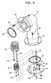
- the overheated steam generator 20 which is provided on the rear wall of the cooking cavity 11, comprises a steam generating vessel 21 having an outlet connected to a steam inlet port 18 provided on the rear wall of the cooking cavity 11and a predetermined amount of water contained in the steam generating vessel 21.
- the overheated steam generator 20 further comprises a first heater 22 which is mounted to a lower portion in the steam generating vessel 21, and a second heater 23 which is mounted to an upper portion in the steam generating vessel 21.
- the steam generating vessel 21 comprises a vacuum insulating vessel, wherein a space is defined therein is insulated from an outside thereof, minimizing heat loss.
- the steam generating vessel 21 further comprises an inner vessel 21a, and an outer vessel 21b which surrounds an outer surface of the inner vessel 21a and is spaced apart from the outer surface of the inner vessel part 21a.
- the steam generating vessel 21 further comprises a shielding material 21c which fills a space between the inner vessel 21a and the outer vessel 21b, to intercept radiant heat originating from an interior of the steam generating vessel 21.
- the space between the inner vessel 21a and the outer vessel 21b is sealed in a vacuum state, when the vacuum state is induced.
- the steam generating vessel 21 further comprises a bent part 21d which is formed by bending an upper end of the steam generating vessel 21 toward the rear wall of the cooking cavity 11, wherein the bent part 21d is connected at a front end thereof on the outlet of the steam generating vessel 21, to the steam inlet port 18 provided on the rear wall of the cooking cavity 11.
- An upper flange 24, which is provided around the outlet of the steam generating vessel 21, is mounted to a predetermined portion of the inner casing 13 around the steam inlet port 18 by a plurality of locking members 25 having a first packing 26 interposed between the upper flange 24 and the inner casing 13 to prevent a leakage of steam.
- a cover 19 having a plurality of steam discharging holes, is mounted to an inner surface of the rear wall of the cooking cavity 11, wherein the overheated steam flows from the overheated steam generator 20 into the cooking cavity 11.
- the steam generating vessel 21 further comprises a lower flange 27 and a lower plate 28, wherein the lower flange 27 is provided around an edge of a lower end of the steam generating vessel 21 and the lower plate 28 is mounted to the lower flange 27 by a plurality of locking members 29 to close an opening of the lower end of the steam generating vessel 21.
- a second packing 30 is interposed between the lower plate 28 and the lower flange 27 to prevent a leakage of water from the steam generating vessel 21.
- first heater 22, mounted to the lower portion in the steam generating vessel 21, and the second heater 23, mounted to the upper portion in the steam generating vessel 21, each have a spiral shape to maximize a heat transferring surface area.
- First and second terminals 22a and 23a which are respectively provided at the first and second heaters 22 and 23, are extended downward, and are supported by the lower plate 28. Accordingly, the first and second heaters 22 and 23 are supported on the lower plate 28.
- third and fourth packings 31a and 31b each are respectively interposed between the first and second terminals 22a and 23a of the first and second heaters 22 and 23 and the lower plate 28 to prevent the leakage of water from the steam generating vessel 21.
- the first heater 22, provided at the lower portion of the steam generating vessel 21, is immersed in the water contained in the steam generating vessel 21, and the second heater 23, provided at the upper portion of the steam generating vessel 21, is placed above the water contained in the steam generating vessel 21 and reaches a maximum water level.
- the overheated steam is generated by allowing the second heater 23 to further heat the steam generated by an operation of the first heater 22 while the steam rises toward the outlet of the steam generating vessel 21.
- the overheated steam generator 20 further comprises a feed hole 32 and a first drain hole 33 formed on the lower plate 28 of the steam generating vessel 21 to feed and drain the water into and from the steam generating vessel 21 respectively. Furthermore, a water level sensor 34 and a water temperature sensor 35 to respectively monitor a level and a temperature of the water contained in the steam generating vessel 21 are mounted to the lower plate 28 of the steam generating vessel 21. A fifth packing 31c is provided between the water level sensor 34 and the lower plate 28 to prevent the leakage of water from the steam generating vessel 21. A sixth packing 31d is provided between the water temperature sensor 35 and the lower plate 28 to prevent the leakage of water from the steam generating vessel 21.
- the water supply pipe 36 is connected to the feed hole 32 of the lower plate 28 to feed the water from an external water source (not shown) to the interior of the steam generating vessel 21.
- a control valve 37 is mounted to a predetermined portion of the water supply pipe 36 to control supplying of the water fed from the external water source into the steam generating vessel 21.
- the control valve 37 is installed in the outer casing 12 of the cabinet 10.
- the overheated steam oven further comprises a cleaning unit to clean the interior of the cooking cavity 11 using the water contained in the steam generating vessel 21 after executing a cooking operation, and a drain unit to drain the water from the interior of the cooking cavity 11 to the outside of the cooking cavity 11.
- the cleaning unit comprises a plurality of spray nozzles 38a, 38b and 38c provided in the cooking cavity 11, a feed pipe 39 which connects the first drain hole 33 of the steam generating vessel 21 to the plurality of spray nozzles 38a, 38b and 38c, and a feed pump 40 mounted to a predetermined portion of the feed pipe 39 to feed the water from the steam generating vessel 21 to the plurality of spray nozzles 38a, 38b and 38c through the feed pipe 39.
- the rotary-type spray nozzle 38a of the plurality of spray nozzles 38a, 38b and 38c is mounted to an upper portion of the cooking cavity 11, and the other spray nozzles 38b and 38c which are the fixed-type spray nozzles, are respectively mounted to both sidewalls of the cooking cavity 11.
- the feed pipe 39 extends from the first drain hole 33 of the steam generating vessel 21 to an outside of an upper wall of the inner casing 13 of the cooking cavity 11, at which a plurality of branch pipes branch from the feed pipe 39 to the plurality of spray nozzles 38a, 38b and 38c, respectively, to feed the water from the steam generating vessel 21 to each of the plurality of spray nozzles 38a, 38b and 38c through the feed pipe 39 having the branch pipes.
- the feed pipe 40 is mounted to the lower end of the steam generating vessel 21, wherein a considerable amount of water remains in the feed pipe 40 even when the steam generating vessel 21 is emptied.
- the drain unit comprises a drain pipe 42 extending from a second drain hole 41 provided on a lower portion of the cooking cavity 11 to the outside of the cabinet 10, and a drain pump 43 mounted to a predetermined portion of the drain pipe 42.
- the overheated steam oven of the present invention further comprises an exhaust duct 50 at an upper portion in the cooking cavity 11 to discharge the steam from the cooking cavity 11 to the outside of the cooking cavity 11.
- the overheated steam oven further comprises an inlet steam temperature sensor 51 and an outlet steam temperature sensor 52.
- the inlet steam temperature sensor 51 is installed inside the cover 19 which covers the steam inlet port 18, to monitor a temperature of the overheated steam discharged from the steam generating vessel 21 into the cooking cavity 11 through the steam inlet port 18.
- the outlet steam temperature sensor 52 is installed in the exhaust duct 50 to monitor a temperature of the steam discharged from the cooking cavity 11 to the outside of the cooking cavity 11.
- the water in the steam generating vessel 21 is heated by the first heater 22 to generate steam.
- the steam is generated by boiling the water, which is contained in the lower portion of the steam generating vessel 21, by the first heater 22 immersed in the water.
- the steam generated by the first heater 22 rises in the steam generating vessel 21, thus being further heated by the second heater 23 to produce overheated steam.
- the overheated steam is then supplied into the cooking cavity 11 through the outlet of the steam generating vessel 21.
- the foods in the cooking cavity 11 are then cooked by the heat of the overheated steam.
- the steam is discharged from the cooking cavity 11 to the outside of the cooking cavity 11 through the exhaust duct 50 provided at the upper portion of the cooking cavity 11.
- the overheated steam oven of the present invention produces overheated steam while minimizing heat loss, because the steam generating vessel 21 has the insulating construction and the outlet of the steam generating vessel 21 is mounted to the rear wall of the cooking cavity 11. Since the overheated steam oven rapidly supplies the overheated steam into the cooking cavity 11, the energy loss is further minimized. Also, since the first heater 22 is immersed in the water contained in the steam generating vessel 21, the overheated steam oven rapidly boils the water in the steam generating vessel 21. Furthermore, because the steam produced by the first heater 22 is further heated by the second heater 23, the overheated steam oven of the present invention produces the overheated steam within a short period of time while reducing energy requirements.
- the cleaning-mode operation to clean the interior of the cooking cavity 11 comprises a steam cleaning process to clean the cooking cavity 11 by use of steam, a hot water cleaning process to clean the cooking cavity 11 by spraying hot water which is supplied from the steam generating vessel 21 into the cooking cavity 11, and a drying process to dry the cooking cavity 11 by use of overheated steam.
- a control unit (not shown) of the overheated steam oven determines whether a cleaning start signal has been input from the cleaning key 15d of the control panel 15 by a manipulation of the user in operation 60.
- the cleaning start signal is input to the control unit only when the user continuously presses the cleaning key 15d for at least a predetermined period of time or repeatedly presses the cleaning key 15d at least a predetermined number of times. Therefore, the control unit determines that the cleaning-mode operation must be started when the user continuously presses the cleaning key 15d for at least the predetermined period of time or repeatedly presses the cleaning key 15d at least the predetermined number of times.
- the control unit informs the user of the execution of the cleaning-mode operation by use of the alarm unit of the control panel 15 in operation 61.
- the alarm unit informs the user of the execution of the cleaning-mode operation by producing flickering alarm light from the alarm lamp 15e and/or producing alarm voice from the alarm speaker 15f.
- the control unit informs the user of the execution of the cleaning operation by displaying letter information on the display 15a.
- the temperature Ts of the steam to be supplied into the cooking cavity 11 is measured by use of the inlet steam temperature sensor 51 in operation 62, and the control unit determines whether the temperature Ts of the steam is maintained within a predetermined reference range Trs (approximately 100°C ⁇ 110°C), suitable for effectively executing the steam cleaning process, in operation 63, based on a signal output from the inlet steam temperature sensor 51.
- Trs approximately 100°C ⁇ 110°C
- the steam cleaning process is performed to soak the parts of the food, which are stuck on the inner surface of the walls of the cooking cavity 11, in water by supplying the steam into the cooking cavity, allowing the parts of the food to be easily removed from the walls of the cooking cavity 11.
- the control unit determines whether the temperature Ts of the steam is lower than a lowest point (approximately 100°C) of the predetermined reference range Trs (approximately 100°C ⁇ 110°C), in operation 64.
- the first heater 22 of the overheated steam generator 20 is operated to boil the water in the steam generating vessel 21 in operation 65.
- the control unit stops the operation of the first heater 22 of the overheated steam generator 20 in operation 66, thus cooling the steam.
- the above-mentioned operations 62, 63, 64, 65 and 66 of the steam cleaning process are performed to supply the steam having appropriate temperatures, suitable for effectively executing the steam cleaning process, into the cooking cavity 11 even when the user starts the cleaning operation by manipulating the cleaning key 15d immediately after a cooking operation of the overheated steam oven finished the steam generating vessel 21 may produce extremely hot steam, or after a considerable time has passed since the finish of the cooking operation the steam generating vessel 21 may not produce any steam from the water contained therein and a sensed temperature of air in the steam generating vessel 21 is lower than approximately 100°C.
- the control unit measures a temperature Tw of the water in the steam generating vessel 21 by use of the water temperature sensor 35 in operation 68, and determines in operation 69 whether the measured temperature Tw of the water is equal to or higher than a predetermined reference Trw (approximately 60°C) which is suitable for effectively executing the water cleaning process.
- Trw a predetermined reference
- the water cleaning process is executed for a predetermined time period in operation 71.
- the control unit operates the first heater 22 of the steam generating vessel 21 in operation 70, heating the water contained in the steam generating vessel 21.
- the hot water is pumped by the feed pump 40 to be forcibly fed through the feed pipe 39 from the steam generating vessel 21 to the plurality of spray nozzles 38a, 38b and 38c which are provided in the cooking cavity 11.
- the hot water is sprayed into the cooking cavity 11 from the plurality of spray nozzles 38a, 38b and 38c, thereby cleaning the interior of the cooking cavity 11.
- the drain pump 43 is operated to drain the water from the cooking cavity 11 to the outside of the cabinet 10.
- the temperature Ts of the steam to be supplied into the cooking cavity 11 is measured again by use of the inlet steam temperature sensor 51 in operation 72, and the control unit determines whether the temperature Ts of the steam is equal to or higher than a predetermined reference Tro (approximately 200°C), suitable for effectively executing the drying process, in operation 73, based on a signal output from the inlet steam temperature sensor 51. That is, the control unit determines whether the steam is the overheated steam in operation 73.
- a predetermined reference Tro approximately 200°C
- the control unit determines that the steam is the overheated steam wherein the temperature Ts is equal to or higher than the predetermined reference Tro (approximately 200°C)
- the overheated steam is continuously supplied into the cooking cavity 11 for a predetermined time period in operation 75 to execute the drying process to dry the cleaned interior of the cooking cavity 11 by use of the overheated steam.
- both the first heater 22 and the second heater 23 of the steam generating vessel 21 are operated in operation 74 to overheat the steam to produce the overheated steam, prior to supplying the overheated steam into the cooking cavity 11.
- the present invention provides an overheated steam oven and a method of controlling the overheated steam oven, which efficiently cleans an interior of a cooking cavity using hot water and overheated steam that are supplied from a steam generating vessel of an overheated steam generator.
Landscapes
- Engineering & Computer Science (AREA)
- Chemical & Material Sciences (AREA)
- Food Science & Technology (AREA)
- Life Sciences & Earth Sciences (AREA)
- Chemical Kinetics & Catalysis (AREA)
- Combustion & Propulsion (AREA)
- Mechanical Engineering (AREA)
- General Engineering & Computer Science (AREA)
- Cleaning By Liquid Or Steam (AREA)
- Commercial Cooking Devices (AREA)
- Cookers (AREA)
- Electric Ovens (AREA)
Applications Claiming Priority (2)
| Application Number | Priority Date | Filing Date | Title |
|---|---|---|---|
| KR1020030063745A KR20050027460A (ko) | 2003-09-15 | 2003-09-15 | 과열증기 조리장치 및 그 제어방법 |
| KR2003063745 | 2003-09-15 |
Publications (1)
| Publication Number | Publication Date |
|---|---|
| EP1517092A1 true EP1517092A1 (de) | 2005-03-23 |
Family
ID=34192225
Family Applications (1)
| Application Number | Title | Priority Date | Filing Date |
|---|---|---|---|
| EP04252952A Withdrawn EP1517092A1 (de) | 2003-09-15 | 2004-05-20 | Ofen mit überhitztem Dampf und zugehöriges Steuerverfahren |
Country Status (5)
| Country | Link |
|---|---|
| US (1) | US6909071B2 (de) |
| EP (1) | EP1517092A1 (de) |
| JP (1) | JP3824612B2 (de) |
| KR (1) | KR20050027460A (de) |
| CN (1) | CN1292192C (de) |
Cited By (12)
| Publication number | Priority date | Publication date | Assignee | Title |
|---|---|---|---|---|
| EP2040005A1 (de) * | 2007-09-21 | 2009-03-25 | Samsung Electronics Co., Ltd. | Kochgerät und Verfahren zur Dampfreinigungssteuerung dafür |
| WO2008044844A3 (en) * | 2006-10-10 | 2009-09-03 | Lg Electronics Inc. | Cooking apparatus and cleaning method for the same |
| EP1821039A3 (de) * | 2006-02-17 | 2010-06-23 | Alto-Shaam, Inc. | System und Verfahren zur Begrenzung des Hitze- und Dampfverlustes vor dem Öffnen einer Ofentür |
| CN103340220A (zh) * | 2013-07-12 | 2013-10-09 | 中国农业科学院农产品加工研究所 | 一种烤制装置 |
| EP2703729A1 (de) * | 2012-08-28 | 2014-03-05 | Electrolux Home Products Corporation N.V. | Garofen mit Innenraum und Reinigungsvorrichtung |
| EP2708819A1 (de) * | 2012-09-17 | 2014-03-19 | ELECTROLUX PROFESSIONAL S.p.A. | Selbstreinigender Lebensmittelkochherd |
| WO2015164239A1 (en) * | 2014-04-22 | 2015-10-29 | Illinois Tool Works Inc. | Oven with steam water separation |
| WO2020094294A1 (en) * | 2018-11-07 | 2020-05-14 | Arcelik Anonim Sirketi | A cooking device comprising a washing system |
| US10677473B2 (en) | 2014-04-22 | 2020-06-09 | Illinois Tool Works Inc. | Oven with cleaning system and grease and water flow separation |
| US10969113B2 (en) | 2014-04-22 | 2021-04-06 | Illinois Tool Works Inc. | Oven with steam water flow directors |
| DE102020202503A1 (de) | 2020-02-27 | 2021-09-02 | BSH Hausgeräte GmbH | Haushalts-Dampfgargerät und Verfahren zum Betreiben eines Haushalts-Dampfgargeräts |
| DE102020212058A1 (de) | 2020-09-24 | 2022-03-24 | BSH Hausgeräte GmbH | Haushalts-Dampfgargerät mit Überhitzer |
Families Citing this family (66)
| Publication number | Priority date | Publication date | Assignee | Title |
|---|---|---|---|---|
| DE10207306B4 (de) * | 2002-02-21 | 2005-09-01 | Angelo Po Grandi Cucine S.P.A., Carpi | Verfahren zur automatischen Garraumreinigung |
| TWI314768B (en) * | 2003-09-04 | 2009-09-11 | United Microelectronics Corp | Method of manufacturing metal-oxide-semiconductor transistor |
| KR20050026597A (ko) * | 2003-09-09 | 2005-03-15 | 삼성전자주식회사 | 증기 조리장치 |
| KR20050052083A (ko) * | 2003-11-29 | 2005-06-02 | 삼성전자주식회사 | 과열증기 조리장치 |
| KR101132331B1 (ko) | 2004-07-14 | 2012-04-05 | 삼성전자주식회사 | 가열조리장치 및 그 제어방법 |
| US20060249137A1 (en) * | 2005-05-03 | 2006-11-09 | Malcolm Reay | System and method for draining water from a steam oven |
| US20060251784A1 (en) * | 2005-05-03 | 2006-11-09 | Sells Joel M | Method for cooking meat using steam |
| US20060251785A1 (en) | 2005-05-06 | 2006-11-09 | Stefania Fraccon | Method for cooking food using steam |
| JP2006329494A (ja) * | 2005-05-25 | 2006-12-07 | Matsushita Electric Ind Co Ltd | 高周波加熱装置 |
| KR100691224B1 (ko) * | 2005-05-31 | 2007-03-09 | 삼성전자주식회사 | 증기조리장치 및 그 조리실 청소 방법 |
| KR100725737B1 (ko) * | 2005-06-30 | 2007-06-08 | 삼성전자주식회사 | 조리장치 및 그 배수제어방법 |
| US7745763B2 (en) * | 2005-07-11 | 2010-06-29 | Whirlpool Corporation | Method for baking bread using steam |
| JP3868464B1 (ja) * | 2005-07-26 | 2007-01-17 | シャープ株式会社 | 加熱調理器 |
| US7168233B1 (en) * | 2005-12-12 | 2007-01-30 | General Electric Company | System for controlling steam temperature |
| CN2873035Y (zh) * | 2005-12-19 | 2007-02-28 | 威力士有限公司 | 蒸、烤二合一炉具 |
| US20070175884A1 (en) * | 2006-01-31 | 2007-08-02 | Atul Saksena | Steam cooker with steam delivery device |
| KR101041077B1 (ko) * | 2006-09-28 | 2011-06-13 | 삼성전자주식회사 | 스팀발생장치 및 이를 갖는 가열조리장치 |
| US7867534B2 (en) * | 2006-10-18 | 2011-01-11 | Whirlpool Corporation | Cooking appliance with steam generator |
| KR100745585B1 (ko) * | 2007-04-10 | 2007-08-02 | 삼성전자주식회사 | 증기발생장치를 갖춘 조리기의 온도제어방법 |
| JP4804419B2 (ja) * | 2007-05-22 | 2011-11-02 | アール・ビー・コントロールズ株式会社 | グリル装置 |
| US8207477B2 (en) | 2007-11-26 | 2012-06-26 | Whirlpool Corporation | Method for cooking vegetables using steam |
| US20090136640A1 (en) * | 2007-11-26 | 2009-05-28 | Whirlpool Corporation | Method for Baking a Casserole Using Steam |
| KR20100034108A (ko) * | 2008-09-23 | 2010-04-01 | 엘지전자 주식회사 | 오븐 |
| KR101152560B1 (ko) | 2009-04-06 | 2012-06-01 | 엘지전자 주식회사 | 조리기기의 스팀발생장치 세척방법 |
| KR101152540B1 (ko) | 2009-04-06 | 2012-06-01 | 엘지전자 주식회사 | 조리기기 세척방법 |
| JP5329303B2 (ja) * | 2009-05-25 | 2013-10-30 | ホシザキ電機株式会社 | 加熱調理器 |
| WO2011003781A2 (de) * | 2009-07-09 | 2011-01-13 | BSH Bosch und Siemens Hausgeräte GmbH | Dampfgargerätevorrichtung |
| KR101450568B1 (ko) * | 2009-07-21 | 2014-10-14 | 엘지전자 주식회사 | 조리기기 |
| DE102009055148A1 (de) | 2009-12-22 | 2011-06-30 | BSH Bosch und Siemens Hausgeräte GmbH, 81739 | Dampferzeugungssystem für ein Haushaltsgerät und Verfahren zum Montieren eines solchen Dampferzeugungssystems |
| JP5066218B2 (ja) * | 2010-04-22 | 2012-11-07 | 株式会社東芝 | 加熱調理装置 |
| US9903597B2 (en) * | 2010-04-28 | 2018-02-27 | Sharp Kabushiki Kaisha | Cooking device including buffer chamber |
| US8783243B2 (en) | 2010-10-25 | 2014-07-22 | General Electric Company | Lockout system for surface burners of a cooking appliance |
| US8373098B2 (en) | 2010-12-13 | 2013-02-12 | General Electric Company | Oven appliance cleaning system using heat and steam cycle |
| CN102635892A (zh) * | 2011-02-11 | 2012-08-15 | 许求鑫 | 取暖、洗浴一体化装置 |
| EP2511614B1 (de) * | 2011-04-14 | 2016-07-06 | Electrolux Home Products Corporation N.V. | Verfahren zum Betreiben eines Dampfgarers und Dampfgarer |
| KR101217996B1 (ko) * | 2011-09-27 | 2013-01-02 | 린나이코리아 주식회사 | 스팀 컨벡션 오븐의 자동 청소 정지 방법 |
| EP2703739B1 (de) * | 2012-08-31 | 2015-07-29 | Electrolux Home Products Corporation N.V. | Kochherd mit Ofeninnenraum und Dampfkochanordnung |
| WO2014088345A1 (ko) * | 2012-12-05 | 2014-06-12 | 코웨이 주식회사 | 스팀 발생기 |
| CN104042103B (zh) * | 2013-03-13 | 2017-12-29 | 东莞市微电环保科技有限公司 | 一种半干烧式高效电蒸炉 |
| JP5299830B1 (ja) * | 2013-04-09 | 2013-09-25 | 株式会社マスダック | 過熱蒸気発生ノズル |
| JP6201096B2 (ja) * | 2014-05-22 | 2017-09-27 | 株式会社Gushout | 加熱装置および耕耘装置 |
| US10517306B1 (en) * | 2015-02-03 | 2019-12-31 | Udi Meirav | Device for conditioning baked goods |
| KR101624582B1 (ko) * | 2015-06-26 | 2016-05-26 | 이재현 | 온수배출장치를 갖춘 즉석식품 자동조리기 |
| JP6689149B2 (ja) * | 2015-07-08 | 2020-04-28 | 友田セーリング株式会社 | 過熱蒸気を用いた加熱調理機および加熱調理方法 |
| CN105476460B (zh) * | 2016-01-25 | 2018-07-17 | 台州千玛供应链管理有限公司 | 一种智能式多层独立蒸笼 |
| WO2017188526A1 (ko) * | 2016-04-25 | 2017-11-02 | 주식회사 프라임 | 스팀 컨벡션 오븐 |
| KR101734447B1 (ko) | 2016-04-25 | 2017-05-11 | 주식회사프라임 | 스팀 컨벡션 오븐 |
| NL2017410B1 (en) * | 2016-09-02 | 2018-03-09 | Fri Jado Bv | System comprising a self-cleaning oven, and method for cleaning a self-cleaning oven |
| KR102556053B1 (ko) * | 2016-09-09 | 2023-07-18 | 삼성전자주식회사 | 조리기기 및 그 제어방법 |
| JP6912767B2 (ja) * | 2016-11-01 | 2021-08-04 | 清己 吉村 | 連続加熱処理装置 |
| JP6849185B2 (ja) * | 2016-11-01 | 2021-03-24 | 清己 吉村 | ドラム型連続加熱処理装置 |
| KR102656201B1 (ko) | 2017-01-03 | 2024-04-09 | 삼성전자주식회사 | 조리기기 |
| KR102039647B1 (ko) * | 2017-11-03 | 2019-11-26 | 주식회사프라임 | 조리장치용 세척 시스템 |
| CN109316081A (zh) * | 2018-01-26 | 2019-02-12 | 志邦家居股份有限公司 | 一种高温蒸汽式自清洁烤箱 |
| KR102455063B1 (ko) * | 2018-04-04 | 2022-10-14 | 엘지전자 주식회사 | 조리기기 및 그의 제어방법 |
| CN109008594A (zh) * | 2018-11-01 | 2018-12-18 | 杭州老板电器股份有限公司 | 具有蒸汽烹饪功能的烹饪电器及烘干控制方法 |
| CN109699694A (zh) * | 2018-12-03 | 2019-05-03 | 珠海格力电器股份有限公司 | 一种烤箱的自清洁方法及其烤箱 |
| KR102133286B1 (ko) * | 2018-12-14 | 2020-07-13 | 엘지전자 주식회사 | 조리실의 자동 세척이 가능한 전자 조리 기기 |
| CN111631588B (zh) * | 2019-06-27 | 2022-05-17 | 上海爱餐机器人(集团)有限公司 | 烹饪腔体清洗控制方法、装置、介质、控制系统及炒菜机 |
| JP7312041B2 (ja) * | 2019-06-28 | 2023-07-20 | エスペック株式会社 | 調理環境形成装置及び調理器 |
| CN111317374A (zh) * | 2020-04-20 | 2020-06-23 | 珠海格力电器股份有限公司 | 自清洁烤箱及其清洗方法 |
| JP7465156B2 (ja) * | 2020-06-11 | 2024-04-10 | ホシザキ株式会社 | 加熱調理器 |
| IT202000020491A1 (it) | 2020-08-26 | 2022-02-26 | S P M Eng S R L | Dispositivo di pulitura per forni, forno e procedimento di pulitura |
| KR102187274B1 (ko) * | 2020-09-08 | 2020-12-04 | 박세근 | 생선 조리기 |
| CN116491824B (zh) * | 2022-01-04 | 2025-11-07 | 杭州九阳小家电有限公司 | 一种食品加工机的清洗控制方法 |
| EP4513083A4 (de) * | 2022-04-18 | 2025-11-26 | Tineco Intelligent Tech Co Ltd | Dampferzeuger und intelligente vorrichtung |
Citations (4)
| Publication number | Priority date | Publication date | Assignee | Title |
|---|---|---|---|---|
| DE2842771A1 (de) * | 1978-09-30 | 1980-04-10 | Lechmetall Landsberg Gmbh | Vorrichtung und verfahren zur waermebehandlung von nahrungsmitteln, insbesondere zur zubereitung von speisen |
| EP0191267A1 (de) * | 1985-01-21 | 1986-08-20 | Menu-System Ernst Wüst | Dämpfer |
| FR2593587A1 (fr) * | 1986-01-29 | 1987-07-31 | Seb Sa | Procede pour la cuisson des aliments en presence de vapeur d'eau et appareil de cuisson s'y rapportant |
| DE4223451A1 (de) * | 1992-07-16 | 1994-01-20 | Eloma Gmbh | Gargerät |
Family Cites Families (9)
| Publication number | Priority date | Publication date | Assignee | Title |
|---|---|---|---|---|
| US3639725A (en) * | 1971-03-03 | 1972-02-01 | Thomas J Maniscalco | Steam-generating apparatus |
| JPS5922132B2 (ja) * | 1978-05-08 | 1984-05-24 | 株式会社東芝 | 蒸気発生器付高周波加熱装置 |
| US5158064A (en) * | 1991-05-13 | 1992-10-27 | Willis Thomas J | Steam drying element for steam cooking device |
| JP2899471B2 (ja) | 1992-03-16 | 1999-06-02 | 松下電器産業株式会社 | スチーム調理器 |
| US5649476A (en) * | 1994-08-22 | 1997-07-22 | Production Engineered Designs, Inc. | Steam generator assembly and steam cooking appliances using same |
| KR0152145B1 (ko) * | 1995-07-10 | 1998-10-01 | 김광호 | 전자렌지 |
| US6157006A (en) * | 1998-11-04 | 2000-12-05 | Metro Industries, Inc. | High humidity apparatus |
| JP2001355844A (ja) | 2000-06-16 | 2001-12-26 | Matsushita Electric Ind Co Ltd | 加熱調理装置 |
| JP2002071138A (ja) | 2000-08-28 | 2002-03-08 | Johnson Boiler Kk | オーブン調理器 |
-
2003
- 2003-09-15 KR KR1020030063745A patent/KR20050027460A/ko not_active Ceased
-
2004
- 2004-03-22 JP JP2004083472A patent/JP3824612B2/ja not_active Expired - Fee Related
- 2004-05-10 US US10/841,489 patent/US6909071B2/en not_active Expired - Fee Related
- 2004-05-20 CN CNB2004100458209A patent/CN1292192C/zh not_active Expired - Fee Related
- 2004-05-20 EP EP04252952A patent/EP1517092A1/de not_active Withdrawn
Patent Citations (4)
| Publication number | Priority date | Publication date | Assignee | Title |
|---|---|---|---|---|
| DE2842771A1 (de) * | 1978-09-30 | 1980-04-10 | Lechmetall Landsberg Gmbh | Vorrichtung und verfahren zur waermebehandlung von nahrungsmitteln, insbesondere zur zubereitung von speisen |
| EP0191267A1 (de) * | 1985-01-21 | 1986-08-20 | Menu-System Ernst Wüst | Dämpfer |
| FR2593587A1 (fr) * | 1986-01-29 | 1987-07-31 | Seb Sa | Procede pour la cuisson des aliments en presence de vapeur d'eau et appareil de cuisson s'y rapportant |
| DE4223451A1 (de) * | 1992-07-16 | 1994-01-20 | Eloma Gmbh | Gargerät |
Cited By (17)
| Publication number | Priority date | Publication date | Assignee | Title |
|---|---|---|---|---|
| EP1821039A3 (de) * | 2006-02-17 | 2010-06-23 | Alto-Shaam, Inc. | System und Verfahren zur Begrenzung des Hitze- und Dampfverlustes vor dem Öffnen einer Ofentür |
| WO2008044844A3 (en) * | 2006-10-10 | 2009-09-03 | Lg Electronics Inc. | Cooking apparatus and cleaning method for the same |
| US8215232B2 (en) | 2006-10-10 | 2012-07-10 | Lg Electronics Inc. | Cooking apparatus and cleaning method for the same |
| EP2040005A1 (de) * | 2007-09-21 | 2009-03-25 | Samsung Electronics Co., Ltd. | Kochgerät und Verfahren zur Dampfreinigungssteuerung dafür |
| EP2703729A1 (de) * | 2012-08-28 | 2014-03-05 | Electrolux Home Products Corporation N.V. | Garofen mit Innenraum und Reinigungsvorrichtung |
| WO2014032986A1 (en) * | 2012-08-28 | 2014-03-06 | Electrolux Home Products Corporation N. V. | A cooking oven with an oven cavity and a cleaning apparatus |
| US9599347B2 (en) | 2012-09-17 | 2017-03-21 | Electrolux Professional S.P.A. | Self-cleaning food cooking oven |
| EP2708819A1 (de) * | 2012-09-17 | 2014-03-19 | ELECTROLUX PROFESSIONAL S.p.A. | Selbstreinigender Lebensmittelkochherd |
| CN103340220A (zh) * | 2013-07-12 | 2013-10-09 | 中国农业科学院农产品加工研究所 | 一种烤制装置 |
| WO2015164239A1 (en) * | 2014-04-22 | 2015-10-29 | Illinois Tool Works Inc. | Oven with steam water separation |
| US10408463B2 (en) | 2014-04-22 | 2019-09-10 | Illinois Tool Works Inc. | Oven with steam water separation |
| US10677473B2 (en) | 2014-04-22 | 2020-06-09 | Illinois Tool Works Inc. | Oven with cleaning system and grease and water flow separation |
| US10969113B2 (en) | 2014-04-22 | 2021-04-06 | Illinois Tool Works Inc. | Oven with steam water flow directors |
| WO2020094294A1 (en) * | 2018-11-07 | 2020-05-14 | Arcelik Anonim Sirketi | A cooking device comprising a washing system |
| DE102020202503A1 (de) | 2020-02-27 | 2021-09-02 | BSH Hausgeräte GmbH | Haushalts-Dampfgargerät und Verfahren zum Betreiben eines Haushalts-Dampfgargeräts |
| WO2021170402A1 (de) | 2020-02-27 | 2021-09-02 | BSH Hausgeräte GmbH | Haushalts-dampfgargerät und verfahren zum betreiben eines haushalts-dampfgargeräts |
| DE102020212058A1 (de) | 2020-09-24 | 2022-03-24 | BSH Hausgeräte GmbH | Haushalts-Dampfgargerät mit Überhitzer |
Also Published As
| Publication number | Publication date |
|---|---|
| KR20050027460A (ko) | 2005-03-21 |
| US6909071B2 (en) | 2005-06-21 |
| CN1292192C (zh) | 2006-12-27 |
| JP2005090940A (ja) | 2005-04-07 |
| US20050056634A1 (en) | 2005-03-17 |
| CN1598400A (zh) | 2005-03-23 |
| JP3824612B2 (ja) | 2006-09-20 |
Similar Documents
| Publication | Publication Date | Title |
|---|---|---|
| US6909071B2 (en) | Overheated steam oven and method of controlling the same | |
| EP1535549B1 (de) | Überhitzter Dampfofen | |
| US7049550B2 (en) | Overheated steam oven | |
| US6911626B2 (en) | Overheated steam oven | |
| US7323662B2 (en) | Heating apparatus for cooking | |
| US7341055B2 (en) | Overheated steam oven | |
| EP1514475B1 (de) | Dampfofen | |
| US6906291B2 (en) | Overheated steam oven | |
| CN107208902B (zh) | 加热烹调器 | |
| CN101784843A (zh) | 蒸气烹调器 | |
| US20050121433A1 (en) | Steam oven having an inner casing including a vacuum | |
| KR100526210B1 (ko) | 증기조리장치 | |
| JP6267309B2 (ja) | 蒸気調理器 | |
| KR100691224B1 (ko) | 증기조리장치 및 그 조리실 청소 방법 | |
| JP2005160807A (ja) | 炊飯器 | |
| KR100495632B1 (ko) | 증기 조리장치 | |
| JPH11193926A (ja) | コンベクションオーブン及びそれに用いる炊飯釜 | |
| KR100688938B1 (ko) | 증기발생장치를 갖춘 조리기의 배기시스템 및 그 제어방법 | |
| KR100471077B1 (ko) | 제빵기 | |
| JP2009063197A (ja) | 蒸気調理器 | |
| KR20060073223A (ko) | 전자레인지의 가열제어방법 | |
| JP2015129596A (ja) | 加熱調理器 |
Legal Events
| Date | Code | Title | Description |
|---|---|---|---|
| PUAI | Public reference made under article 153(3) epc to a published international application that has entered the european phase |
Free format text: ORIGINAL CODE: 0009012 |
|
| AK | Designated contracting states |
Kind code of ref document: A1 Designated state(s): AT BE BG CH CY CZ DE DK EE ES FI FR GB GR HU IE IT LI LU MC NL PL PT RO SE SI SK TR |
|
| AX | Request for extension of the european patent |
Extension state: AL HR LT LV MK |
|
| 17P | Request for examination filed |
Effective date: 20050525 |
|
| AKX | Designation fees paid |
Designated state(s): DE FR GB |
|
| STAA | Information on the status of an ep patent application or granted ep patent |
Free format text: STATUS: THE APPLICATION HAS BEEN WITHDRAWN |
|
| 18W | Application withdrawn |
Effective date: 20071001 |