EP1517623B1 - Porte-cle a manoeuvre simplifiee - Google Patents
Porte-cle a manoeuvre simplifiee Download PDFInfo
- Publication number
- EP1517623B1 EP1517623B1 EP03730388A EP03730388A EP1517623B1 EP 1517623 B1 EP1517623 B1 EP 1517623B1 EP 03730388 A EP03730388 A EP 03730388A EP 03730388 A EP03730388 A EP 03730388A EP 1517623 B1 EP1517623 B1 EP 1517623B1
- Authority
- EP
- European Patent Office
- Prior art keywords
- lug
- ring
- key
- turns
- gap
- Prior art date
- Legal status (The legal status is an assumption and is not a legal conclusion. Google has not performed a legal analysis and makes no representation as to the accuracy of the status listed.)
- Expired - Lifetime
Links
- 229910000831 Steel Inorganic materials 0.000 claims description 2
- 239000000463 material Substances 0.000 claims description 2
- 239000010959 steel Substances 0.000 claims description 2
- 210000000078 claw Anatomy 0.000 claims 1
- 230000000717 retained effect Effects 0.000 claims 1
- 210000000282 nail Anatomy 0.000 description 5
- 230000037431 insertion Effects 0.000 description 4
- 238000003780 insertion Methods 0.000 description 4
- 210000004905 finger nail Anatomy 0.000 description 2
- 238000004026 adhesive bonding Methods 0.000 description 1
- 239000002184 metal Substances 0.000 description 1
- 238000000926 separation method Methods 0.000 description 1
- 230000035939 shock Effects 0.000 description 1
Images


Classifications
-
- A—HUMAN NECESSITIES
- A44—HABERDASHERY; JEWELLERY
- A44B—BUTTONS, PINS, BUCKLES, SLIDE FASTENERS, OR THE LIKE
- A44B15/00—Key-rings
- A44B15/005—Fobs
-
- A—HUMAN NECESSITIES
- A44—HABERDASHERY; JEWELLERY
- A44B—BUTTONS, PINS, BUCKLES, SLIDE FASTENERS, OR THE LIKE
- A44B15/00—Key-rings
- A44B15/007—Openers
-
- Y—GENERAL TAGGING OF NEW TECHNOLOGICAL DEVELOPMENTS; GENERAL TAGGING OF CROSS-SECTIONAL TECHNOLOGIES SPANNING OVER SEVERAL SECTIONS OF THE IPC; TECHNICAL SUBJECTS COVERED BY FORMER USPC CROSS-REFERENCE ART COLLECTIONS [XRACs] AND DIGESTS
- Y10—TECHNICAL SUBJECTS COVERED BY FORMER USPC
- Y10T—TECHNICAL SUBJECTS COVERED BY FORMER US CLASSIFICATION
- Y10T70/00—Locks
- Y10T70/80—Parts, attachments, accessories and adjuncts
- Y10T70/8432—For key-operated mechanism
- Y10T70/8676—Key holders
- Y10T70/8784—Parallel key loops, coaxially mounted, individually movable
Definitions
- the present invention relates to a key ring consisting of a ring, preferably circular, having a first complete turn and at least a second turn section, preferably a second turn, joined to the first turn and resiliently biased against the first turn, the first turn and the second turn section being separated by a gap through which keys are passed to secure them to or remove the keychain.
- This type of key ring is well known in the field.
- the main advantage of this type of keychain is that the keys are well attached to the ring and can not inadvertently detach from it, especially as was the case in previously made keychains that had a system. closing and opening for example by clip or ratchet which could inadvertently open after a shock for example and drop a key or several keys keychain.
- a key ring consisting of a ring, preferably circular, having a first complete turn and at least a second turn section, preferably a second turn, joined to the first turn and elastically biased against the first turn spire, the first turn and the second turn being separated by a gap extending between the two free ends of the two turns and between the two turns, interstice through which is passed a key head to attach to the key ring or the detach, in which there is provided a post having a main body and a nail-shaped portion having a leading edge sufficiently thin to be inserted into the gap and wide enough to rotate the tenon sufficiently apart from each other to rotate allowing the passage of a key head between them and a chain to fix the stud away from the ring and at a sufficient distance thereof to allow the insertion of the pin into the gap.
- the nail-shaped portion has a thickness large enough for the nail-shaped portion to stand on edge between the turns without the user having to hold it with the
- the present invention is directed to a key holder of the type described above, which makes it possible to keep the two turns apart from each other without the aid of the fingers in a position of spaced turns in which the user has both hands free. to introduce its keys into the ring, the position of separated turns being on the one hand easier to implement than in the prior art, and secondly more stable than in the key holder of the prior art.
- the keychain is as defined in claim 1, improvements being defined in the subclaims.
- the relative dimensions of the auxiliary ring, the leading edge and the opening of the tenon being chosen so that when the post is rotated by about 90 ° with the leading edge inserted by its width into the gap between the two turns, the auxiliary ring is in contact with the pin so that the rotation of the tenon is no longer possible in a direction of rotation, the tenon is thus maintained between the two turns so that a user can insert a key between the two turns without having to hold the post.
- the inner diameter of the auxiliary ring is substantially equal to or greater than the sum of the useful width of the tenon and the two thicknesses of the two turns, in the direction perpendicular to the plane defined by the ring.
- the auxiliary ring is in contact with the tenon on two sides of the tenon.
- the thin nail-shaped tenon has two lateral edges parallel to one another and at a distance from each other, the distance between these two lateral edges, which corresponds to the said distance useful, being sufficient so that, when the post is placed in the interstice with the two lateral edges respectively in contact with a turn and with the other turn, the gap is open enough to allow the insertion of a key.
- the angle-shaped tenon has a beveled leading edge. This bevel allows a particularly effective attack of the gap to separate the two turns.
- the opening has a dimension in the direction parallel to the leading edge of the post substantially equal to or greater than, preferably substantially equal to, the sum of the effective width of the leading edge and the two thicknesses in the direction perpendicular to the plane of the ring of the two turns.
- the pin is made of the same material as the ring, and in particular steel.
- the body portion of the tenon comprises an enlarged head on which are displayed, by gluing or engraving, information, including patterns or logos advertising or brands.
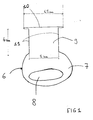
- a circular ring comprising a first turn 1 and a second turn 2.
- the first turn 1 extends from a first free end 3 to a portion 4 of separation of the two turns, the portion 4 being shaped half-bridge to allow the continuation of the ring by the second turn 2 above the first turn 1.
- the second turn 2 extends from this portion 4 to a free end 5.
- the two turns are resiliently biased against each other by the elasticity of the metal in which the ring is formed. When you want to insert a key in the keychain, it should "open" one of the free ends by separating one of the turns of the other. Then, once the two turns have been separated at a distance from each other, a key can be inserted through its pierced head and slide along the gap between the two turns to bring it inside the ring.
- a part 6 comprising an enlarged head portion 7 in which is formed an opening 8 and a portion 9 in the form of nail forming a nail.
- This pin 9 has a substantially rectangular shape having a leading edge 10 and two mutually parallel lateral support edges 11. The leading edge is slightly beveled.
- the part 6 is substantially flat in shape, having two opposite planar faces.
- a ring 12 of small size ensures the attachment of the part 6 or 6 'to the ring by hooking in the opening 8 or 8'.
- the dimensions of the ring 12 and the opening 8 or 8 ' are such that the tenon can be at a sufficient distance from the ring to be able to be operated, that is to say to be inserted into the interstice between the two turns then to be turned on 90 °, that is to say a quarter turn, to be put in so-called perpendicular position, that we see at the figure 4 wherein the two turns themselves remote from one another for insertion of a key head between the two turns.
- the head 7 or 7 'of the tenon-shaped piece has inscriptions or advertising logos or marks. This enlarged flat-shaped head makes it easy to manipulate the tenon to insert it between the two turns.
- another form than a flat shape can also be provided.
- the main ring has an outer diameter of 32 mm, a thickness in the direction perpendicular to the 3 mm ring, a thickness in the direction parallel to the plane of the ring equal to 3mm.
- the auxiliary ring 12 has an outer diameter of 12mm, a thickness in the direction perpendicular to the ring of 2mm, and a thickness in the direction parallel to the ring of 1.5mm.
- the nail-shaped tenon has a leading edge which extends over 6.5mm, the two lateral edges extending over 4mm, a distance which corresponds substantially to the thickness (3mm) in the direction parallel to the plane of the ring or is slightly above it.
- the diameter of the small ring is substantially equal to the thickness of the two turns in the plane perpendicular to the ring plus the distance (5mm) between the two lateral retaining edges.
- effective width of the leading edge is meant the width of an interstice formed between the two turns, in the direction perpendicular to the plane of the ring, when the leading edge is inserted between the two turns and rotated. about 90 °.
- plane of the ring is meant the plane in which the ring is located when the two turns are contiguous.
Landscapes
- Adornments (AREA)
- Supports Or Holders For Household Use (AREA)
- Switches With Compound Operations (AREA)
- Slide Fasteners, Snap Fasteners, And Hook Fasteners (AREA)
- Lock And Its Accessories (AREA)
Description
- La présente invention se rapporte à un porte-clé constitué d'un anneau, de préférence circulaire, ayant une première spire complète et au moins un tronçon de deuxième spire, de préférence une deuxième spire, jointive à la première spire et sollicitée élastiquement contre la première spire, la première spire et le tronçon de deuxième spire étant séparés par un interstice par lequel on fait passer des clés pour les fixer au porte-clé ou les en détacher.
- Ce type d'anneau porte-clé est bien connu dans le domaine. L'avantage principal de ce type de porte-clé est que les clés sont bien attachées à l'anneau et ne peuvent pas s'en détacher par inadvertance, notamment comme ceci était le cas dans des porte-clés réalisés antérieurement qui avaient un système de fermeture et d'ouverture par exemple par clip ou par cliquet qui pouvaient par inadvertance s'ouvrir à la suite d'un choc par exemple et laisser tomber une clé ou plusieurs clés du porte-clé.
- Cependant, l'avantage de ce porte-clé en anneau à deux spires rappelées l'une contre l'autre élastiquement est obtenu en contrepartie d'un autre inconvénient, qui n'existait pas pour les porte-clés de l'art antérieur à ouverture et fermeture à cliquet ou à clip, à savoir qu'il est difficile de mettre une clé dans le porte-clé ou d'en enlever une clé, la deuxième spire étant rappelée élastiquement contre la première spire par une force élastique importante contre laquelle il faut exercer une force, notamment par exemple avec un ongle et il n'est pas rare de se « casser » un ongle lorsqu'on essaye d'enlever une clé du porte-clé ou de mettre une clé dans un porte-clé en anneau à double spires de ce genre.
- De
US-A-4.543.860 on connaît en outre un porte-clé, constitué d'un anneau, de préférence circulaire, ayant une première spire complète et au moins un tronçon de deuxième spire, de préférence une deuxième spire, jointive à la première spire et rappelée élastiquement contre la première spire, la première spire et la deuxième spire étant séparées par un interstice s'étendant entre les deux extrémités libres des deux spires et entre les deux spires, interstice par lequel on fait passer une tête de clé pour la fixer au porte-clé ou l'en détacher, dans lequel il est prévu un tenon ayant un corps principal et une partie en forme d'ongle ayant un bord d'attaque suffisamment mince pour pouvoir être inséré dans l'interstice et suffisamment large pour, par rotation du tenon, écarter suffisamment les deux spires l'une de l'autre pour permettre le passage d'une tête de clé entre elles et une chaîne pour fixer le tenon à distance de l'anneau et ce à une distance suffisante de celui-ci pour permettre l'insertion du tenon dans l'interstice. En outre, la partie en forme d'ongle a une épaisseur assez grande pour que la partie en forme d'ongle tienne sur chant entre les spires sans que l'utilisateur ait à la tenir avec les doigts, de sorte que il a les deux mains libres pour faire passer la tête d'une clé dans l'interstice. - Cependant la position sur chant de la partie en forme d'ongle entre les deux spires, sensiblement perpendiculairement, n'est pas très stable dans ces porte clé de l'art antérieur, de sorte d'une part qu'il est difficile d'amener l'ongle à tenir de soi même entre les spires et d'autre part qu'il arrive fréquemment que l'ongle quitte de soi même la position sur chant, perpendiculairement aux deux spires, et l'utilisateur doit de nouveau écarter les spires et y placer entre elles l'ongle sur chant.
- La présente invention vise un porte clé du genre décrit précédemment , qui permet de maintenir écartées l'une de l'autre les deux spires sans l'aide des doigts dans une position de spires écartées dans laquelle l'utilisateur a les deux mains de libres pour introduire ses clés dans l'anneau, la position de spires écartées étant d'une part plus facile à mettre en place que dans l'art antérieur, et d'autre part plus stable que dans les porte clé de l'art antérieur.
- Le document
US-A-4543860 décrit un porte clé suivant le préambule de la revendication 1. - Suivant l'invention, le porte clé est tel que défini à la revendication 1, des perfectionnements étant définis aux sous revendications.
- Les dimensions relatives de l'anneau auxiliaire, du bord d'attaque et de l'ouverture du tenon étant choisies de sorte que lorsque le tenon est tourné de 90° environ avec le bord d'attaque inséré par sa largeur dans l'interstice entre les deux spires, l'anneau auxiliaire est en contact avec le tenon de sorte que la rotation du tenon n'est plus possible dans une direction de rotation, le tenon étant ainsi maintenu entre les deux spires de sorte qu'un utilisateur peut insérer une clé entre les deux spires sans avoir à tenir le tenon.
- En prévoyant un tel agencement, on s'assure que lorsque le tenon est pivoté à environ 90° par rapport aux spires, il est en contact avec l'anneau auxiliaire de sorte qu'il tient de lui même dans cette position perpendiculaire au plan de l'anneau, et ce de manière particulièrement stable, en raison de l'action de maintien de l'anneau auxiliaire sur le tenon avec lequel il est en contact.
- Le diamètre intérieur de l'anneau auxiliaire est sensiblement égal ou supérieur à la somme de la largeur utile du tenon et des deux épaisseurs des deux spires, dans la direction perpendiculaire au plan défini par l'anneau.
- Suivant un perfectionnement de l'invention, l'anneau auxiliaire est en contact avec le tenon de deux cotés du tenon.
- Suivant un mode de réalisation préféré, le tenon mince en forme d'ongle comporte deux bords latéraux parallèles l'un à l'autre et à distance l'un de l'autre, la distance entre ces deux bords latéraux, qui correspond à la distance dite utile, étant suffisante pour que, lorsque le tenon est placé dans l'interstice avec les deux bords latéraux respectivement en contact avec une spire et avec l'autre spire, l'interstice soit suffisamment ouvert pour permettre l'insertion d'une clé.
- Ainsi, par le fait de prévoir ces deux bords parallèles latéraux, on peut, en tournant le tenon sur 90° après son insertion dans l'interstice, maintenir de manière très stable à distance les deux spires l'une de l'autre avec interposition perpendiculairement du tenon qui repose par ses bords latéraux respectivement contre les deux spires.
- Suivant un mode de réalisation particulièrement préféré de l'invention et notamment particulièrement simple à insérer, le tenon en forme d'angle comporte un bord d'attaque biseauté. Ce biseau permet une attaque particulièrement efficace de l'interstice en vue de séparer les deux spires.
- Suivant un mode de réalisation particulièrement stable, l'ouverture a une dimension dans la direction parallèle au bord d'attaque du tenon sensiblement égale ou supérieure, de préférence sensiblement égale, à la somme de la largeur utile du bord d'attaque et des deux épaisseurs dans la direction perpendiculaire au plan de l'anneau des deux spires.
- Suivant un mode de réalisation préféré de l'invention, le tenon est en le même matériau que l'anneau, et notamment en acier.
- Suivant un mode de réalisation particulièrement intéressant en vue de diffuser dans l'esprit du public une marque de commerce, la partie formant corps du tenon comporte une tête élargie sur laquelle sont affichées, par collage ou gravure, des informations, notamment des motifs ou logos publicitaires ou de marques.
- Aux dessins donnés uniquement à titre d'exemple, il est représenté un mode de réalisation préféré de l'invention.
- La
figure 1 représente un premier mode de réalisation d'une pièce en forme de tenon suivant l'invention. - La
figure 2 est une vue en perspective d'un mode de réalisation d'un porte-clé suivant l'invention, en position fermée de l'anneau ; - La
figure 3 est une vue en perspective du porte-clé de lafigure 2 en une position intermédiaire dans laquelle un tenon sépare les deux spires l'une de l'autre ; et - La
figure 4 est une vue en perspective du porte-clé desfigures 2 et3 dans laquelle le tenon sépare les deux spires l'une de l'autre dans une position tenant d'elle même. - A la
figure 2 il est représenté un anneau circulaire comportant une première spire 1 et une deuxième spire 2. La première spire 1 s'étend d'une première extrémité libre 3 jusqu'à une partie 4 de séparation des deux spires, la partie 4 étant en forme de demi-pont pour permettre la poursuite de l'anneau par la deuxième spire 2 au-dessus de la première spire 1 . La deuxième spire 2 s'étend à partir de cette partie 4 jusqu'à une extrémité libre 5. Les deux spires sont rappelées élastiquement l'une contre l'autre par l'élasticité du métal en lequel est constitué l'anneau. Lorsque l'on veut insérer une clé dans le porte-clé, il convient «d'ouvrir» l'une des extrémités libres en séparant l'une des spires de l'autre. Ensuite, une fois que les deux spires ont été séparées à distance l'une de l'autre, on peut insérer une clé par sa tête percée et la faire coulisser le long de l'interstice entre les deux spires jusqu'à l'amener à l'intérieur de l'anneau. - Il est prévu à la
figure 1 une pièce 6 comportant une partie 7 de tête agrandie dans laquelle est formée une ouverture 8 et une partie 9 en forme de tenon formant ongle. Ce tenon 9 a une forme sensiblement rectangulaire en ayant un bord d'attaque 10 et deux bords latéraux 11 de support mutuellement parallèles. Le bord 10 d'attaque est légèrement biseauté. La pièce 6 est de forme sensiblement plate, ayant deux faces planes opposées. - Aux
figures 2 ,3 et 4 , il est représenté un autre mode de réalisation de la pièce 6, désignée par la référence 6', qui comporte deux parties 9' en forme de tenon. - Un anneau 12 de petite dimension assure la fixation de la pièce 6 ou 6' à l'anneau par accrochage dans l'ouverture 8 ou 8'. Les dimensions de l'anneau 12 et de l'ouverture 8 ou 8' sont telles que le tenon peut être à une distance suffisante de l'anneau pour pouvoir être manoeuvré, c'est-à-dire pour pouvoir être inséré dans l'interstice entre les deux spires puis ensuite être tourné sur 90°, c'est-à-dire un quart de tour, pour être mis en position dite perpendiculaire, que l'on voit à la
figure 4 dans laquelle les deux spires tiennent d'elles même à distance l'une de l'autre en vue d'une insertion d'une tête de clé entre les deux spires. La tête 7 ou 7' de la pièce en forme de tenon comporte des inscriptions ou des logos publicitaires ou de marques. Cette tête agrandie de forme plate permet de manipuler facilement le tenon pour l'insérer entre les deux spires. Cependant, une autre forme qu'une forme plate peut également être prévue. - Suivant un mode de réalisation donné à titre d'exemple, l'anneau principal a un diamètre extérieur de 32mm, une épaisseur dans le sens perpendiculaire à l'anneau de 3mm, une épaisseur dans le sens parallèle au plan de l'anneau égale à 3mm.
- L'anneau 12 auxiliaire a un diamètre extérieur de 12mm, une épaisseur dans le sens perpendiculaire à l'anneau de 2mm, et une épaisseur dans le sens parallèle à l'anneau de 1,5mm. Le tenon en forme d'ongle a un bord d'attaque qui s'étend sur 6,5mm, les deux bords latéraux s'étendant sur 4mm, distance qui correspond sensiblement à l'épaisseur (3mm) dans le sens parallèle au plan de l'anneau ou est légèrement supérieure à celle-ci. Le diamètre du petit anneau est sensiblement égal à l'épaisseur des deux spires dans le plan perpendiculaire à l'anneau plus la distance (5mm) entre les deux bords latéraux de maintien.
- On entend par largeur utile du bord 10 d'attaque la largeur d'un interstice formé entre les deux spires, dans la direction perpendiculaire au plan de l'anneau, lorsque le bord d'attaque est inséré entre les deux spires et tourné d'environ 90°.
- On entend par plan de l'anneau, le plan dans lequel se trouve l'anneau lorsque les deux spires sont jointives.
Claims (8)
- Porte clé, constitué d'un anneau, de préférence circulaire, ayant une première spire (1) complète et au moins une deuxième spire (2), jointive à la première spire et rappelée élastiquement contre la première spire, la première spire et la deuxième spire étant séparées par un interstice s'étendant entre deux extrémités (3,5) libres des deux spires et entre les deux spires, interstice par lequel on peut faire passer une tête de clé pour la fixer au porte clé ou l'en détacher, dans lequel il est prévu un tenon (9,9') en forme d'ongle ayant un bord (10) d'attaque suffisamment mince pour pouvoir être inséré dans l'interstice et suffisamment large pour, par rotation du tenon, écarter suffisamment les deux spires l'une de l'autre pour permettre le passage d'une tête de clé entre elles, et ayant un anneau (12) auxiliaire pour fixer le tenon à l'anneau, le tenon ayant une ouverture (8, 8') par laquelle passe l'anneau auxiliaire, characterisé en ce que le diamètre intérieur de l'anneau (12) auxiliaire est sensiblement égal ou supérieur à la somme de la largeur utile du tenon et des deux épaisseurs des deux spires, dans la direction perpendiculaire au plan défini par l'anneau, de sorte que lorsque le tenon est tourné de 90° environ avec le bord d'attaque inséré par sa largeur dans l'interstice entre les deux spires, l'anneau auxiliaire est en contact avec le tenon de sorte que la rotation du tenon n'est plus possible dans une direction de rotation, le tenon étant ainsi maintenu entre les deux spires de sorte qu'un utilisateur peut insérer une clé entre les deux spires sans avoir à tenir le tenon.
- Porte clé suivant la revendication 1, caractérisé en ce que, lorsque le tenon est tourné de 90° environ avec le bord d'attaque inséré par sa largeur dans l'interstice entre les deux spires, et le tenon ayant deux faces opposées, l'anneau auxiliaire est en contact avec chaque face du tenon.
- Porte-clé suivant l'une des revendications 1 à 2, caractérisé en ce que le tenon (9 ; 9') mince en forme d'ongle comporte deux bords (11) latéraux parallèles l'un à l'autre et à distance l'un de l'autre, la distance entre ces deux bords latéraux étant suffisante pour que, lorsque le tenon est placé dans l'interstice avec les deux bords latéraux respectivement en contact avec une spire et avec l'autre spire, l'interstice soit suffisamment ouvert pour permettre l'insertion d'une tête de clé.
- Porte-clé suivant l'une des revendications 1 à 3, caractérise en ce que l'ouverture (8,8') a une dimension dans la direction parallèle au bord (10) d'attaque du tenon sensiblement égale ou supérieure, de préférence sensiblement égale, à la somme de la largeur utile du bord d'attaque et des deux épaisseurs dans la direction perpendiculaire au plan de l'anneau des deux spires.
- Porte-clé suivant l'une des revendications 1 à 4, caractérisé en ce que le bord (10) d'attaque est biseauté.
- Porte-clé suivant l'une des revendications 1 à 5, caractérisé en ce que le tenon (9 ; 9') est en le même matériau que l'anneau ou l'anneau auxiliaire, et notamment en acier.
- Porte-clé suivant l'une des revendications 1 à 6, caractérisé en ce que le tenon (9 ; 9') comporte une tête de clé agrandie sur laquelle sont affichées, par collage ou gravure, des informations, notamment des motifs ou logos publicitaires ou de marques.
- Porte clé suivant l'une des revendications précédentes, caractérisé en ce que le tenon est de forme sensiblement plan.
Applications Claiming Priority (3)
| Application Number | Priority Date | Filing Date | Title |
|---|---|---|---|
| FR0207468 | 2002-06-18 | ||
| FR0207468A FR2840779B1 (fr) | 2002-06-18 | 2002-06-18 | Porte-cle a manoeuvre simplifiee |
| PCT/IB2003/002004 WO2003105620A1 (fr) | 2002-06-18 | 2003-05-26 | Porte-cle a manoeuvre simplifiee |
Publications (2)
| Publication Number | Publication Date |
|---|---|
| EP1517623A1 EP1517623A1 (fr) | 2005-03-30 |
| EP1517623B1 true EP1517623B1 (fr) | 2008-09-10 |
Family
ID=29595330
Family Applications (1)
| Application Number | Title | Priority Date | Filing Date |
|---|---|---|---|
| EP03730388A Expired - Lifetime EP1517623B1 (fr) | 2002-06-18 | 2003-05-26 | Porte-cle a manoeuvre simplifiee |
Country Status (11)
| Country | Link |
|---|---|
| US (1) | US6860130B2 (fr) |
| EP (1) | EP1517623B1 (fr) |
| JP (1) | JP2005529660A (fr) |
| CN (1) | CN1309327C (fr) |
| AT (1) | ATE407585T1 (fr) |
| AU (1) | AU2003241068A1 (fr) |
| BR (1) | BR0305088A (fr) |
| CA (1) | CA2488726A1 (fr) |
| DE (1) | DE60323491D1 (fr) |
| FR (1) | FR2840779B1 (fr) |
| WO (1) | WO2003105620A1 (fr) |
Cited By (1)
| Publication number | Priority date | Publication date | Assignee | Title |
|---|---|---|---|---|
| DE102019122668B3 (de) * | 2019-08-22 | 2020-12-10 | Leica Camera Aktiengesellschaft | Schlüsselring-Montagehilfe |
Families Citing this family (16)
| Publication number | Priority date | Publication date | Assignee | Title |
|---|---|---|---|---|
| US6737056B1 (en) * | 1999-01-15 | 2004-05-18 | Genentech, Inc. | Polypeptide variants with altered effector function |
| US7650770B2 (en) * | 2006-07-25 | 2010-01-26 | David Maxwell | Key ring tool |
| US20090090151A1 (en) * | 2007-10-05 | 2009-04-09 | Stinson Margaret M | Key ring spreader |
| US20100071518A1 (en) * | 2008-02-15 | 2010-03-25 | Margaret Marie Stinson | Key ring spreader |
| US20090235705A1 (en) * | 2008-03-18 | 2009-09-24 | Knapton Roland B | Key ring tool |
| US20100126242A1 (en) * | 2008-11-24 | 2010-05-27 | Thomas Perlmutter | Tool for Opening a Split Ring Key Holder |
| USD665993S1 (en) * | 2009-05-28 | 2012-08-28 | Margaret Marie Pyle | Key ring spreader |
| WO2011123009A1 (fr) * | 2010-03-29 | 2011-10-06 | Drosselmeyer Designgroup Aktiebolag | Anneau brisé avec espace compressible |
| ES2373285B1 (es) * | 2010-06-01 | 2012-10-22 | Juan Manuel Romero Monrabal | Abre anillas para llaveros. |
| USD755505S1 (en) * | 2015-01-26 | 2016-05-10 | Romain Marteau | Separable ring |
| US10492571B2 (en) | 2016-05-12 | 2019-12-03 | Caffeinate Labs, Inc | Indented key ring |
| US9854879B2 (en) | 2016-05-12 | 2018-01-02 | Caffeinate Labs, Inc. | Flat key ring |
| US9808052B1 (en) | 2016-05-18 | 2017-11-07 | George Edward Mouzakis, III | Tool for manipulating split rings |
| USD840677S1 (en) * | 2017-06-01 | 2019-02-19 | Forrest Andrew Duncan | Keyring |
| CN108606417B (zh) * | 2018-07-09 | 2021-04-20 | 安徽新大陆特种涂料有限责任公司 | 一种圆环夹持装置 |
| GB201813879D0 (en) * | 2018-08-24 | 2018-10-10 | Eadie Gregor | A key ring opener |
Family Cites Families (12)
| Publication number | Priority date | Publication date | Assignee | Title |
|---|---|---|---|---|
| US4325273A (en) * | 1980-06-12 | 1982-04-20 | James Gibbons | Opener for split ring key holder |
| US4543860A (en) * | 1982-09-29 | 1985-10-01 | Meter James A Van | Key ring attachment |
| CN2074111U (zh) * | 1990-04-24 | 1991-04-03 | 徐启定 | 安全钥匙扣 |
| JPH06253920A (ja) * | 1993-03-05 | 1994-09-13 | Toyo Commun Equip Co Ltd | 多重リングの構造 |
| JPH08173302A (ja) * | 1994-12-22 | 1996-07-09 | ▲よ▼平名 克 | 隙間を設けた螺旋型金属輪のキーホルダー |
| USD374344S (en) * | 1995-07-19 | 1996-10-08 | World's Best Products, Inc. | Combined pendant and opener for a split ring key holder |
| US5722277A (en) * | 1997-02-05 | 1998-03-03 | Williams; James M. | Key ring opener and method of use |
| GB2329353B (en) * | 1997-09-17 | 2002-09-04 | Melville Berwick | Keyring tool |
| USD404621S (en) * | 1998-02-23 | 1999-01-26 | Liese Grover J | Split ring opening device |
| GB2350579B (en) * | 1999-02-25 | 2003-06-18 | Alfred Edward Briggs | Key ring splitter |
| CN2398875Y (zh) * | 1999-12-21 | 2000-10-04 | 罗润林 | 新型匙扣 |
| US6681608B1 (en) * | 2002-09-03 | 2004-01-27 | Hope, Iii Paul M. | Key ring opener assembly |
-
2002
- 2002-06-18 FR FR0207468A patent/FR2840779B1/fr not_active Expired - Fee Related
-
2003
- 2003-05-26 US US10/476,241 patent/US6860130B2/en not_active Expired - Fee Related
- 2003-05-26 DE DE60323491T patent/DE60323491D1/de not_active Expired - Fee Related
- 2003-05-26 CA CA 2488726 patent/CA2488726A1/fr not_active Abandoned
- 2003-05-26 WO PCT/IB2003/002004 patent/WO2003105620A1/fr not_active Ceased
- 2003-05-26 EP EP03730388A patent/EP1517623B1/fr not_active Expired - Lifetime
- 2003-05-26 AT AT03730388T patent/ATE407585T1/de not_active IP Right Cessation
- 2003-05-26 BR BR0305088A patent/BR0305088A/pt not_active IP Right Cessation
- 2003-05-26 JP JP2004512538A patent/JP2005529660A/ja not_active Ceased
- 2003-05-26 AU AU2003241068A patent/AU2003241068A1/en not_active Abandoned
- 2003-05-26 CN CNB038012847A patent/CN1309327C/zh not_active Expired - Fee Related
Cited By (1)
| Publication number | Priority date | Publication date | Assignee | Title |
|---|---|---|---|---|
| DE102019122668B3 (de) * | 2019-08-22 | 2020-12-10 | Leica Camera Aktiengesellschaft | Schlüsselring-Montagehilfe |
Also Published As
| Publication number | Publication date |
|---|---|
| CA2488726A1 (fr) | 2003-12-24 |
| FR2840779B1 (fr) | 2004-09-17 |
| DE60323491D1 (de) | 2008-10-23 |
| FR2840779A1 (fr) | 2003-12-19 |
| BR0305088A (pt) | 2004-09-21 |
| AU2003241068A1 (en) | 2003-12-31 |
| US6860130B2 (en) | 2005-03-01 |
| WO2003105620A1 (fr) | 2003-12-24 |
| CN1568152A (zh) | 2005-01-19 |
| ATE407585T1 (de) | 2008-09-15 |
| US20040118174A1 (en) | 2004-06-24 |
| EP1517623A1 (fr) | 2005-03-30 |
| CN1309327C (zh) | 2007-04-11 |
| JP2005529660A (ja) | 2005-10-06 |
Similar Documents
| Publication | Publication Date | Title |
|---|---|---|
| EP1517623B1 (fr) | Porte-cle a manoeuvre simplifiee | |
| EP1133936B1 (fr) | Fermoir de bracelet | |
| EP2888424B1 (fr) | Dispositif amovible d'attache sur objets longilignes ou filiformes | |
| EP2137094A1 (fr) | Dispositif d'ouverture de bouteilles et son procede de fabrication | |
| EP1680777A1 (fr) | Porte-plectre | |
| EP0466656B1 (fr) | Dispositif de fermeture d'un bracelet | |
| FR3076694A1 (fr) | Fermoir magnetique ergonomique | |
| EP2654512B1 (fr) | Dispositif d'aide au recouvrement d'une couette par une housse de couette et d'aide à l'étirage d'un drap | |
| CH674438B5 (fr) | ||
| BE1025776B1 (fr) | Ensemble de fermeture perfectionné | |
| EP0460141A1 (fr) | Pince pour retenir en place une piece de tissu sur le sol. | |
| CH609542A5 (en) | Key ring | |
| FR2814138A1 (fr) | Pret-a-monter de fixation d'un porte-bidon | |
| EP3699376B1 (fr) | Serrure à contrôle par aimants | |
| EP1683937A1 (fr) | Système de fermeture de porte d'enveloppe électrique | |
| EP2709852A1 (fr) | Ensemble composé d'un instrument d'écriture plat et d'un élément de maintien de l'instrument d'écriture a l'intérieur d'un cahier ou carnet | |
| BE902373A (fr) | Garniture pourvue d'un porte-etiquette destinee a des clefs. | |
| CH699481A2 (fr) | Support pour montre bracelet. | |
| FR2618231A1 (fr) | Montre-agrafe comprenant un calibre de montre et une agrafe elastique. | |
| EP1688056A1 (fr) | Attache de bracelet | |
| FR2459625A1 (fr) | Nouvel entourage de piece ou de medaille | |
| FR2832834A3 (fr) | Clef pour activer le dispositif de verrouillage du caddie de libre-service | |
| FR2778871A1 (fr) | Dispositif de reliure de feuilles volantes sous forme de bloc-notes | |
| JP2001097378A (ja) | キャップ付き缶 | |
| FR2631728A1 (fr) | Panneau de signalisation et profiles pour la fabrication d'un tel panneau |
Legal Events
| Date | Code | Title | Description |
|---|---|---|---|
| PUAI | Public reference made under article 153(3) epc to a published international application that has entered the european phase |
Free format text: ORIGINAL CODE: 0009012 |
|
| 17P | Request for examination filed |
Effective date: 20050118 |
|
| AK | Designated contracting states |
Kind code of ref document: A1 Designated state(s): AT BE BG CH CY CZ DE DK EE ES FI FR GB GR HU IE IT LI LU MC NL PT RO SE SI SK TR |
|
| AX | Request for extension of the european patent |
Extension state: AL LT LV MK |
|
| DAX | Request for extension of the european patent (deleted) | ||
| 17Q | First examination report despatched |
Effective date: 20070515 |
|
| GRAP | Despatch of communication of intention to grant a patent |
Free format text: ORIGINAL CODE: EPIDOSNIGR1 |
|
| GRAS | Grant fee paid |
Free format text: ORIGINAL CODE: EPIDOSNIGR3 |
|
| GRAA | (expected) grant |
Free format text: ORIGINAL CODE: 0009210 |
|
| AK | Designated contracting states |
Kind code of ref document: B1 Designated state(s): AT BE BG CH CY CZ DE DK EE ES FI FR GB GR HU IE IT LI LU MC NL PT RO SE SI SK TR |
|
| REG | Reference to a national code |
Ref country code: GB Ref legal event code: FG4D Free format text: NOT ENGLISH |
|
| REG | Reference to a national code |
Ref country code: CH Ref legal event code: EP |
|
| REG | Reference to a national code |
Ref country code: CH Ref legal event code: NV Representative=s name: E. BLUM & CO. AG PATENT- UND MARKENANWAELTE VSP |
|
| REG | Reference to a national code |
Ref country code: IE Ref legal event code: FG4D Free format text: LANGUAGE OF EP DOCUMENT: FRENCH |
|
| REF | Corresponds to: |
Ref document number: 60323491 Country of ref document: DE Date of ref document: 20081023 Kind code of ref document: P |
|
| PG25 | Lapsed in a contracting state [announced via postgrant information from national office to epo] |
Ref country code: FI Free format text: LAPSE BECAUSE OF FAILURE TO SUBMIT A TRANSLATION OF THE DESCRIPTION OR TO PAY THE FEE WITHIN THE PRESCRIBED TIME-LIMIT Effective date: 20080910 Ref country code: SI Free format text: LAPSE BECAUSE OF FAILURE TO SUBMIT A TRANSLATION OF THE DESCRIPTION OR TO PAY THE FEE WITHIN THE PRESCRIBED TIME-LIMIT Effective date: 20080910 Ref country code: AT Free format text: LAPSE BECAUSE OF FAILURE TO SUBMIT A TRANSLATION OF THE DESCRIPTION OR TO PAY THE FEE WITHIN THE PRESCRIBED TIME-LIMIT Effective date: 20080910 |
|
| NLV1 | Nl: lapsed or annulled due to failure to fulfill the requirements of art. 29p and 29m of the patents act | ||
| REG | Reference to a national code |
Ref country code: IE Ref legal event code: FD4D |
|
| PG25 | Lapsed in a contracting state [announced via postgrant information from national office to epo] |
Ref country code: IE Free format text: LAPSE BECAUSE OF FAILURE TO SUBMIT A TRANSLATION OF THE DESCRIPTION OR TO PAY THE FEE WITHIN THE PRESCRIBED TIME-LIMIT Effective date: 20080910 Ref country code: BG Free format text: LAPSE BECAUSE OF FAILURE TO SUBMIT A TRANSLATION OF THE DESCRIPTION OR TO PAY THE FEE WITHIN THE PRESCRIBED TIME-LIMIT Effective date: 20081210 Ref country code: ES Free format text: LAPSE BECAUSE OF FAILURE TO SUBMIT A TRANSLATION OF THE DESCRIPTION OR TO PAY THE FEE WITHIN THE PRESCRIBED TIME-LIMIT Effective date: 20081221 |
|
| PG25 | Lapsed in a contracting state [announced via postgrant information from national office to epo] |
Ref country code: SK Free format text: LAPSE BECAUSE OF FAILURE TO SUBMIT A TRANSLATION OF THE DESCRIPTION OR TO PAY THE FEE WITHIN THE PRESCRIBED TIME-LIMIT Effective date: 20080910 Ref country code: PT Free format text: LAPSE BECAUSE OF FAILURE TO SUBMIT A TRANSLATION OF THE DESCRIPTION OR TO PAY THE FEE WITHIN THE PRESCRIBED TIME-LIMIT Effective date: 20090210 Ref country code: CZ Free format text: LAPSE BECAUSE OF FAILURE TO SUBMIT A TRANSLATION OF THE DESCRIPTION OR TO PAY THE FEE WITHIN THE PRESCRIBED TIME-LIMIT Effective date: 20080910 Ref country code: RO Free format text: LAPSE BECAUSE OF FAILURE TO SUBMIT A TRANSLATION OF THE DESCRIPTION OR TO PAY THE FEE WITHIN THE PRESCRIBED TIME-LIMIT Effective date: 20080910 Ref country code: NL Free format text: LAPSE BECAUSE OF FAILURE TO SUBMIT A TRANSLATION OF THE DESCRIPTION OR TO PAY THE FEE WITHIN THE PRESCRIBED TIME-LIMIT Effective date: 20080910 |
|
| PLBE | No opposition filed within time limit |
Free format text: ORIGINAL CODE: 0009261 |
|
| STAA | Information on the status of an ep patent application or granted ep patent |
Free format text: STATUS: NO OPPOSITION FILED WITHIN TIME LIMIT |
|
| PG25 | Lapsed in a contracting state [announced via postgrant information from national office to epo] |
Ref country code: DK Free format text: LAPSE BECAUSE OF FAILURE TO SUBMIT A TRANSLATION OF THE DESCRIPTION OR TO PAY THE FEE WITHIN THE PRESCRIBED TIME-LIMIT Effective date: 20080910 Ref country code: EE Free format text: LAPSE BECAUSE OF FAILURE TO SUBMIT A TRANSLATION OF THE DESCRIPTION OR TO PAY THE FEE WITHIN THE PRESCRIBED TIME-LIMIT Effective date: 20080910 |
|
| 26N | No opposition filed |
Effective date: 20090611 |
|
| PG25 | Lapsed in a contracting state [announced via postgrant information from national office to epo] |
Ref country code: IT Free format text: LAPSE BECAUSE OF FAILURE TO SUBMIT A TRANSLATION OF THE DESCRIPTION OR TO PAY THE FEE WITHIN THE PRESCRIBED TIME-LIMIT Effective date: 20080910 |
|
| PGFP | Annual fee paid to national office [announced via postgrant information from national office to epo] |
Ref country code: FR Payment date: 20090520 Year of fee payment: 7 |
|
| BERE | Be: lapsed |
Owner name: LAFINA MANAGEMENT S. A., C/O SWISS BANCOR GROUP Effective date: 20090531 |
|
| PGFP | Annual fee paid to national office [announced via postgrant information from national office to epo] |
Ref country code: DE Payment date: 20090630 Year of fee payment: 7 |
|
| PG25 | Lapsed in a contracting state [announced via postgrant information from national office to epo] |
Ref country code: MC Free format text: LAPSE BECAUSE OF NON-PAYMENT OF DUE FEES Effective date: 20090531 |
|
| GBPC | Gb: european patent ceased through non-payment of renewal fee |
Effective date: 20090526 |
|
| PG25 | Lapsed in a contracting state [announced via postgrant information from national office to epo] |
Ref country code: SE Free format text: LAPSE BECAUSE OF FAILURE TO SUBMIT A TRANSLATION OF THE DESCRIPTION OR TO PAY THE FEE WITHIN THE PRESCRIBED TIME-LIMIT Effective date: 20081210 |
|
| PG25 | Lapsed in a contracting state [announced via postgrant information from national office to epo] |
Ref country code: GB Free format text: LAPSE BECAUSE OF NON-PAYMENT OF DUE FEES Effective date: 20090526 |
|
| PG25 | Lapsed in a contracting state [announced via postgrant information from national office to epo] |
Ref country code: BE Free format text: LAPSE BECAUSE OF NON-PAYMENT OF DUE FEES Effective date: 20090531 |
|
| PG25 | Lapsed in a contracting state [announced via postgrant information from national office to epo] |
Ref country code: GR Free format text: LAPSE BECAUSE OF FAILURE TO SUBMIT A TRANSLATION OF THE DESCRIPTION OR TO PAY THE FEE WITHIN THE PRESCRIBED TIME-LIMIT Effective date: 20081211 |
|
| REG | Reference to a national code |
Ref country code: FR Ref legal event code: ST Effective date: 20110131 |
|
| PG25 | Lapsed in a contracting state [announced via postgrant information from national office to epo] |
Ref country code: DE Free format text: LAPSE BECAUSE OF NON-PAYMENT OF DUE FEES Effective date: 20101201 Ref country code: LU Free format text: LAPSE BECAUSE OF NON-PAYMENT OF DUE FEES Effective date: 20090526 |
|
| PG25 | Lapsed in a contracting state [announced via postgrant information from national office to epo] |
Ref country code: FR Free format text: LAPSE BECAUSE OF NON-PAYMENT OF DUE FEES Effective date: 20100531 |
|
| PG25 | Lapsed in a contracting state [announced via postgrant information from national office to epo] |
Ref country code: HU Free format text: LAPSE BECAUSE OF FAILURE TO SUBMIT A TRANSLATION OF THE DESCRIPTION OR TO PAY THE FEE WITHIN THE PRESCRIBED TIME-LIMIT Effective date: 20090311 |
|
| PGFP | Annual fee paid to national office [announced via postgrant information from national office to epo] |
Ref country code: CH Payment date: 20110519 Year of fee payment: 9 |
|
| PG25 | Lapsed in a contracting state [announced via postgrant information from national office to epo] |
Ref country code: TR Free format text: LAPSE BECAUSE OF FAILURE TO SUBMIT A TRANSLATION OF THE DESCRIPTION OR TO PAY THE FEE WITHIN THE PRESCRIBED TIME-LIMIT Effective date: 20080910 |
|
| PG25 | Lapsed in a contracting state [announced via postgrant information from national office to epo] |
Ref country code: CY Free format text: LAPSE BECAUSE OF FAILURE TO SUBMIT A TRANSLATION OF THE DESCRIPTION OR TO PAY THE FEE WITHIN THE PRESCRIBED TIME-LIMIT Effective date: 20080910 |
|
| REG | Reference to a national code |
Ref country code: CH Ref legal event code: PL |
|
| PG25 | Lapsed in a contracting state [announced via postgrant information from national office to epo] |
Ref country code: CH Free format text: LAPSE BECAUSE OF NON-PAYMENT OF DUE FEES Effective date: 20120531 Ref country code: LI Free format text: LAPSE BECAUSE OF NON-PAYMENT OF DUE FEES Effective date: 20120531 |