EP1518504B1 - Zielgerät für einen Verriegelungsnagel - Google Patents
Zielgerät für einen Verriegelungsnagel Download PDFInfo
- Publication number
- EP1518504B1 EP1518504B1 EP04018246A EP04018246A EP1518504B1 EP 1518504 B1 EP1518504 B1 EP 1518504B1 EP 04018246 A EP04018246 A EP 04018246A EP 04018246 A EP04018246 A EP 04018246A EP 1518504 B1 EP1518504 B1 EP 1518504B1
- Authority
- EP
- European Patent Office
- Prior art keywords
- target device
- oscillation circuits
- plane
- circuits
- intramedullary nail
- Prior art date
- Legal status (The legal status is an assumption and is not a legal conclusion. Google has not performed a legal analysis and makes no representation as to the accuracy of the status listed.)
- Expired - Lifetime
Links
- 210000000988 bone and bone Anatomy 0.000 claims description 14
- 238000011156 evaluation Methods 0.000 claims description 10
- 230000005284 excitation Effects 0.000 claims description 8
- 230000003321 amplification Effects 0.000 claims description 5
- 238000003199 nucleic acid amplification method Methods 0.000 claims description 5
- 230000010355 oscillation Effects 0.000 claims 17
- 230000008685 targeting Effects 0.000 description 4
- 230000005672 electromagnetic field Effects 0.000 description 2
- 239000003990 capacitor Substances 0.000 description 1
- 230000006835 compression Effects 0.000 description 1
- 238000007906 compression Methods 0.000 description 1
- 238000013016 damping Methods 0.000 description 1
- 230000001419 dependent effect Effects 0.000 description 1
- 238000001514 detection method Methods 0.000 description 1
- 238000005553 drilling Methods 0.000 description 1
- 238000001914 filtration Methods 0.000 description 1
- 230000036039 immunity Effects 0.000 description 1
- 239000007943 implant Substances 0.000 description 1
- 238000000034 method Methods 0.000 description 1
- 230000005855 radiation Effects 0.000 description 1
- 230000004936 stimulating effect Effects 0.000 description 1
- 210000000689 upper leg Anatomy 0.000 description 1
Images
Classifications
-
- A—HUMAN NECESSITIES
- A61—MEDICAL OR VETERINARY SCIENCE; HYGIENE
- A61B—DIAGNOSIS; SURGERY; IDENTIFICATION
- A61B17/00—Surgical instruments, devices or methods
- A61B17/16—Instruments for performing osteoclasis; Drills or chisels for bones; Trepans
- A61B17/17—Guides or aligning means for drills, mills, pins or wires
- A61B17/1725—Guides or aligning means for drills, mills, pins or wires for applying transverse screws or pins through intramedullary nails or pins
-
- A—HUMAN NECESSITIES
- A61—MEDICAL OR VETERINARY SCIENCE; HYGIENE
- A61B—DIAGNOSIS; SURGERY; IDENTIFICATION
- A61B17/00—Surgical instruments, devices or methods
- A61B17/16—Instruments for performing osteoclasis; Drills or chisels for bones; Trepans
- A61B17/17—Guides or aligning means for drills, mills, pins or wires
- A61B17/1707—Guides or aligning means for drills, mills, pins or wires using electromagnetic effects, e.g. with magnet and external sensors
-
- A—HUMAN NECESSITIES
- A61—MEDICAL OR VETERINARY SCIENCE; HYGIENE
- A61B—DIAGNOSIS; SURGERY; IDENTIFICATION
- A61B17/00—Surgical instruments, devices or methods
- A61B17/56—Surgical instruments or methods for treatment of bones or joints; Devices specially adapted therefor
- A61B17/58—Surgical instruments or methods for treatment of bones or joints; Devices specially adapted therefor for osteosynthesis, e.g. bone plates, screws or setting implements
- A61B17/68—Internal fixation devices, including fasteners and spinal fixators, even if a part thereof projects from the skin
- A61B17/72—Intramedullary devices, e.g. pins or nails
-
- A—HUMAN NECESSITIES
- A61—MEDICAL OR VETERINARY SCIENCE; HYGIENE
- A61B—DIAGNOSIS; SURGERY; IDENTIFICATION
- A61B90/00—Instruments, implements or accessories specially adapted for surgery or diagnosis and not covered by any of the groups A61B1/00 - A61B50/00, e.g. for luxation treatment or for protecting wound edges
- A61B90/39—Markers, e.g. radio-opaque or breast lesions markers
- A61B2090/397—Markers, e.g. radio-opaque or breast lesions markers electromagnetic other than visible, e.g. microwave
Definitions
- the following invention relates to a target device for a locking nail having two resonant circuits arranged along its longitudinal direction.
- insertable locking nails usually have a plurality of transverse bores through which bone screws are guided to keep the locking nail securely in the bone canal.
- a particular difficulty here is finding the transverse hole in the implanted nail.
- Target devices are used for this purpose.
- the bone is X-rayed and the transverse bores of the locking nail in the bone are visualized on a monitor.
- a target element is shown in the X-ray image, so that on the outside of the bone, a mark lying on the axis of the transverse bore can be made.
- a bow-shaped portion has at least one bore whose axis is aligned with the axis of the transverse bore of the nail when the target device is mounted.
- To guide the drilling tool or the bone screw is also known to insert through the hole of the target device a guide sleeve which is advanced up against the outside of the bone.
- the aiming device is aligned in the field of the oscillating circuits such that a guide channel for the drill connected thereto is aligned with the bone nail along the axis of the transverse bore.
- a disadvantage of this device is that an occurring during driving distortion or compression of the locking nail can not be considered.
- a targeting device for axially aligning a guide sleeve in which the guide sleeves are provided with two pairs of measuring coils which detect the magnetic field of a nail arranged in the cross bore and aligned with the coil.
- the aiming device is positioned so that each pair of the two coils receive an equally strong magnetic field.
- the present invention has for its object to provide a target device for a locking nail, in which the position of the transverse bore can be detected in the locking nail with simple means as accurate and reliable.
- the target device is suitable for aligning a guide sleeve for attaching a drill and / or a bone screw relative to a transverse bore of an inserted locking nail.
- the locking nail has two oscillating circuits arranged along the longitudinal direction of the locking nail.
- the central axis of the guide sleeve coincides substantially with the central axis of the transverse bore.
- the target device has three or more oscillating circuits in a first plane, each of which has the same distance from an in-plane first center. In a second plane extending parallel to the first plane, there are also arranged three or more oscillating circuits which are equidistant from a center located in the second plane.
- First and second planes are arranged relative to one another in such a way that a surface normal to one of the planes runs through the first and the second center.
- the first level is for positioning in an xy plane.
- the axis of the transverse bore extends in the z-direction and the longitudinal direction of the locking nail in the x-direction.
- the target device according to the invention can also be used if the longitudinal direction of the locking nail and the axis of the transverse bore are not orthogonal to one another.
- the first level with the resonant circuits defines the position of the target device in the xy plane.
- the position of the aiming device is sought in which the oscillating circuits in the first plane receive an electromagnetic field of a resonant circuit in the interlocking nail of equal strength. If the position is fixed in the xy plane, it must be ensured that the axis of the guide sleeve or the target device is not tilted with respect to the z-axis or the axis of the transverse bore.
- the second arranged parallel to the first plane level with their resonant circuits. If signals of the same magnitude are also detected by these oscillating circuits, it is ensured that the axes of the guide sleeve and the transverse bore coincide. However, the target device can still be rotated around this axis.
- the signal of a second resonant circuit is measured from the Vernagelungsnagel with the additional pair of resonant circuits. For this purpose, the additional pair of oscillating circuits is aligned perpendicular to the longitudinal direction of the locking nail.
- both oscillating circuits receive signals of the same magnitude, the target device is completely aligned in a precisely defined position relative to the bone nail and the position of the transverse bores can be determined relative to this reference position.
- the additional coil pair coils are aligned in the "y" direction and are thus on both sides of the longitudinal "x" direction.
- the resonant circuits provided in the locking nail and in the target device are preferably operated at their resonant frequency.
- an excitation coil in the target device is provided for exciting these oscillating circuits, which emits a high-frequency pulse for exciting the oscillating circuits in the locking nail.
- oscillating circuits are arranged in a rectangle relative to one another in the first and / or second plane.
- a square is chosen as a rectangle. The rectangular arrangement of the recording resonant circuits in the planes of the target device, the accuracy of the positioning is significantly increased.
- the resonant circuits are arranged in the first and second levels congruent to each other. This means that, when the mutually parallel planes are made to coincide along their surface normal, the resonant circuits in the planes are superimposed.
- the signals received by the oscillating circuits can be forwarded to an internal or external evaluation unit. To indicate the correct position, it is possible for this to be done on the target device itself or on an external display or both.
- the evaluation unit has filter and amplification units, which are tuned to an operating frequency of the resonant circuits.
- the amplifier unit preferably has an amplifier and a bandpass filter, wherein the amplification is effected essentially by an active bandpass filter.
- the amplified and filtered measured values are rectified and digitized via an AD converter.
- the digitized data can be forwarded via a serial interface to a PC for evaluation.
- the additionally or exclusively evaluated data is displayed on the PC in order to indicate the aligned state of the target device and if necessary the direction and / or the amount of the deviation from the aligned position.
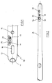
- Fig. 1 shows the tip of a locking nail 10 having a hollow shaft 12 with an opening in the tip 14.
- two transverse bores 16 and 18 are provided in the illustrated embodiment as a slot.
- a recess 20 is made in the shaft wall in the region between the transverse bores 16 and 18.
- two schematically illustrated resonant circuits 22 and 24 are provided in the recess 20 .
- the resonant circuits each have a coil and a capacitor, which are electrically matched to each other.
- the resonant circuits are electrically connected together.
- the target device To stimulate the resonant circuits to oscillate, the target device generates a short high-frequency pulse (RF pulse).
- the frequency of the pulse corresponds to the resonance frequency of the resonant circuit to be excited in the nail or is in the vicinity of the resonant frequency, so that no excessive damping occurs in the resonant circuit.
- the generated RF field excites the respective resonant circuit in the nail.
- After switching off the RF excitation field stored in the resonant circuit energy causes the resonant circuit for the period of a few milliseconds continues to swing and even generates a decaying RF field. This field is used by the target device with its Resonance circuits received and analyzed.
- the generation of the RF pulse takes place in the target device with a large-area coil.
- the stimulating field has a uniform field strength distribution in the entire target area in order to achieve a constant strong excitation of the oscillating circuits in the nail, regardless of the position of the nail in the detection area.
- the excitation of the resonant circuits in the nail is thus in contrast to the German utility model DE 202 04 655 wireless via an RF pulse. This type of excitation makes it possible to use the resonant circuits provided in the nail both as receiving and transmitting oscillating circuits.
- the resonant circuits 22, 24 provided in the recess 20 are electrically insulated by a suitable biocompatible plastic 26. It goes without saying that the coils are also electrically insulated from the shaft wall.
- Fig. 2 shows an alternative embodiment of the locking nail.
- the locking nail 28 has two transverse bores 30 and 32 in the region of its tip.
- the transverse bore 32 is again designed as a slot.
- the recess for the two resonant circuits is in contrast to the embodiment of Fig. 1 not arranged between the holes, but to the transverse bore 30.
- two resonant circuits 36, 38 are provided, wherein resonant circuit 36 extends around the transverse bore 30.
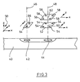
- Fig. 3 shows in a schematic sketch a locking nail 40 with two oscillating circuits 42, 44.
- the coils of the oscillating circuits 42, 44 are arranged in the shaft wall, that their main radiation axes 46, 48 parallel to each other. Further, the coils 42 and 44 are arranged along the longitudinal axis of the locking nail.
- a coordinate system 50 is shown in which the x-axis is along the longitudinal axis of the locking nail extends and the z-axis along the main emission direction 46 and 48.
- four oscillating circuits 54 are arranged in a square. The first plane 52 runs in the xy plane with respect to the drawn coordinate system 50.
- a second plane 56 is provided, in which also four oscillating circuits 58 are arranged in a square to each other.
- the planes 52 and 56 are arranged parallel to each other and the resonant circuits are superimposed with respect to the z-direction.
- the center of the square in the first plane 52 is designated 60, while the center of the square in the second plane 56 is 62.
- the resonant circuits are congruently shown one above another in the embodiment, such an arrangement is not necessary.
- the resonant circuits can also be arranged offset from each other.
- Fig. 3 shows the aligned position of the first plane 52 and the second plane 56, in which the main emission axis 48 pierces the centers 60 and 62.
- the target device is aligned in the xy plane.
- the oscillating circuits 58 must deliver equally strong signals. This condition ensures that both the xy plane is hit and tilt is prevented.
- a rotation of the target device remains about the axis 48.
- an additional pair of receiving swing circuits 64, 66 is provided. The coils 64 and 66 are aligned along the direction labeled "y" and each extending in the xy direction. If the coils 64, 66 also indicate signals of equal magnitude, the orientation of the aiming device with respect to the axis 48 is fixed and a guide sleeve (not shown) points in the direction of one of the transverse bores.
- the transmitter includes two filter and amplifier units, each tuned to the operating frequency of a transmitting coil in the locking nail.
- the connection of the coil unit is done via a 2x8-fachmultiplexerbaustein.
- the multiplexer is controlled by a microcontroller which determines which measuring coil to connect to the amplifier unit.
- the amplifier unit consists of an amplifier and a bandpass filter. To improve the immunity to interference, the majority of the amplifiers is performed by a specially dimensioned active bandpass filter.
- the signal is rectified and forwarded to an A / D converter.
- the A-D converter preferably 12 bits, is controlled by the microcontroller, as is the multiplexer.
- the converted data is then transferred to a PC via a serial link using the microcontroller.
- the PC evaluates the data and graphically represents the location of the target device relative to the transverse bores of the locking nail.
- the coils 42 and 44 are excited via an exciter coil (not shown) in the target device.
- the excitation coil is arranged such that the recording coils 54, 58, 64 and 66 are not disturbed by the RF pulse.
Landscapes
- Health & Medical Sciences (AREA)
- Life Sciences & Earth Sciences (AREA)
- Surgery (AREA)
- Orthopedic Medicine & Surgery (AREA)
- Biomedical Technology (AREA)
- Molecular Biology (AREA)
- Nuclear Medicine, Radiotherapy & Molecular Imaging (AREA)
- Veterinary Medicine (AREA)
- Public Health (AREA)
- Engineering & Computer Science (AREA)
- General Health & Medical Sciences (AREA)
- Heart & Thoracic Surgery (AREA)
- Medical Informatics (AREA)
- Animal Behavior & Ethology (AREA)
- Oral & Maxillofacial Surgery (AREA)
- Dentistry (AREA)
- Physics & Mathematics (AREA)
- Electromagnetism (AREA)
- Neurology (AREA)
- Surgical Instruments (AREA)
- Slide Fasteners, Snap Fasteners, And Hook Fasteners (AREA)
- Breeding Of Plants And Reproduction By Means Of Culturing (AREA)
Description
- Die folgende Erfindung betrifft ein Zielgerät für einen Verriegelungsnagel, der zwei entlang seiner Längsrichtung angeordnete Schwingkreise besitzt.
- In den Unterschenkel- oder Oberschenkelknochen einführbare Verriegelungsnägel weisen zumeist mehrere Querbohrungen auf, durch die Knochenschrauben geführt werden, um den Verriegelungsnagel sicher im Knochenkanal zu halten. Eine besondere Schwierigkeit hierbei ist das Auffinden der Querbohrung beim implantierten Nagel. Hierfür werden Zielgeräte eingesetzt. Bei einer Kategorie von Zielgeräten wird der Knochen mit Röntgenstrahlen durchleuchtet und die Querbohrungen des Verriegelungsnagels in dem Knochen auf einem Monitor sichtbar gemacht. Zusätzlich wird ein Zielelement in dem Röntgenbild dargestellt, so daß an der Außenseite des Knochens eine auf der Achse der Querbohrung liegende Markierung vorgenommen werden kann.
- Bei einer anderen Kategorie von Zielgeräten ist dies fest mit dem implantierbaren Nagel verbunden. Ein bügelartiger Abschnitt weist mindestens eine Bohrung auf, deren Achse mit der Achse der Querbohrung des Nagels ausgerichtet ist, wenn das Zielgerät angebracht ist. Zur Führung des Bohrwerkzeugs bzw. der Knochenschraube ist auch bekannt, durch die Bohrung des Zielgeräts eine Führungshülse zu stecken, die bis gegen die Außenseite des Knochens vorgeschoben wird.
- Aus
US 5,411,503 ist ein Instrument zum Zielen für Verriegelungsnägel in Markknochen bekannt geworden. Bei dem Verfahren wird ein Spieß in den hohlen Schaft des Verriegelungsnagels eingeführt. Der Spieß ist an seinem distalen Ende mit zwei Schwingkreisen versehen. An dem proximalen Ende weist der Spieß einen Anschlag auf. Zur Positionierung wird der Spieß vollständig in den eingetriebenen Verriegelungsnagel eingesetzt, wobei das Anschlagelement an dem freien Ende des Verriegelungsnagels anliegt. Die beiden Schwingkreise am Ende des Spießes werden angeregt und das abgestrahlte elektromagnetische Feld durch entsprechende Sensoren in dem Zielgerät erfaßt. Das Zielgerät wird in dem Feld der Schwingkreise derart ausgerichtet, daß ein mit diesem verbundener Führungskanal für den Bohrer entsprechend der Achse der Querbohrung an dem Knochennagel ausgerichtet ist. Nachteilig an dieser Vorrichtung ist, daß eine während des Eintreibens auftretende Verwindung oder Stauchung des Verriegelungsnagels nicht berücksichtigt werden kann. - Aus
US 5,584,838 ist ein Knochennagel bekannt, in dessen hohlen Schaft ein Element mit einem einzelnen Schwingkreis eingesetzt ist. Der Nagel wird mit eingesetztem Element in den Knochen eingetrieben, so daß die vorstehend beschriebenen Nachteile bei einer Verwindung des Nagels nicht auftreten können. Nachteilig an einem derart ausgebildeten Verriegelungsnagel ist jedoch, daß durch die Verwendung nur eines Schwingkreises ein vergleichsweise aufwendiges Zielgerät erforderlich ist, um den Bohrer auszurichten. Ferner erweist es sich als nachteilig, daß der Schwingkreis genau in dem Kanal der Querbohrung angeordnet ist und nach einer Ausrichtung des Zielgeräts entfernt werden muß. Ein Zielgerät gemäss dem Oberbegriff von Anspruch 1 ist ebenfalls offenbart. - Aus
DE 33 32 642 ist eine weitere Vorrichtung zum Auffinden von Querbohrungen in intramedulären Implantaten bekannt. Hierbei wird ein Magnetfeld in der Querbohrung ausgerichtet und mit einer Magnetfeldmeßeinrichtung von außen die Achse der Querbohrung gemessen. - Aus
EP 0 523 905 ist ein Zielgerät zur axialen Ausrichtung einer Führungshülse bekannt, bei dem die Führungshülsen mit zwei Paaren von Meßspulen versehen sind, die das Magnetfeld einer in dem Nagel angeordneten und mit der Querbohrung ausgerichteten Spule erfassen. Zur Ausrichtung wird das Zielgerät so positioniert, daß jedes Paar der zwei Spulen ein gleich starkes Magnetfeld empfängt. - Der vorliegenden Erfindung liegt die Aufgabe zugrunde, ein Zielgerät für einen Verriegelungsnagel bereitzustellen, bei dem mit einfachen Mitteln möglichst genau und zuverlässig die Position der Querbohrung in dem Verriegelungsnagel erfaßt werden kann.
- Erfindungsgemäß wird die Aufgabe durch ein Zielgerät mit den Merkmalen aus Anspruch 1 gelöst. Vorteilhafte Ausgestaltungen bilden den Gegenstand der Unteransprüche 2 bis 13.
- Das erfindungsgemäße Zielgerät ist geeignet, eine Führungshülse zum Ansetzen eines Bohrers und/oder einer Knochenschraube relativ zu einer Querbohrung eines eingesetzten Verriegelungsnagels auszurichten. Der Verriegelungsnagel besitzt hierzu zwei entlang der Längsrichtung des Verriegelungsnagels angeordnete Schwingkreise. Im ausgerichteten Zustand des Zielgeräts fällt die Mittelachse der Führungshülse im wesentlichen mit der Mittelachse der Querbohrung zusammen. Das Zielgerät besitzt in einer ersten Ebene drei oder mehr Schwingkreise, die von einem in der Ebene liegenden ersten Zentrum jeweils den gleichen Abstand besitzen. In einer zweiten parallel zu der ersten Ebene verlaufenden Ebene sind ebenfalls drei oder mehr Schwingkreise angeordnet, die einen gleichen Abstand von einem in der zweiten Ebene liegenden Zentrum besitzen. Erste und zweite Ebene sind so zueinander angeordnet, daß durch das erste und das zweite Zentrum eine Flächennormale zu einer der Ebenen verläuft. Zusätzlich ist ein Paar von Schwingkreisen beabstandet von der durch die Zentren verlaufenden Geraden vorgesehen, wobei die Verbindungsgerade der Schwingkreise in dem mit dem Verriegelungsnagel ausgerichteten Zustand des Zielgeräts im wesentlichen senkrecht zur Längsrichtung des Verriegelungsnagels steht. Die erste Ebene dient zur Positionierung in einer xy-Ebene. Zur besseren Übersicht verläuft die Achse der Querbohrung in z-Richtung und die Längsrichtung des Verriegelungsnagels in x-Richtung. Selbstverständlich kann das erfindungsgemäße Zielgerät auch eingesetzt werden, wenn Längsrichtung des Verriegelungsnagels und Achse der Querbohrung nicht orthogonal zueinander stehen. Bei dieser Geometrie definiert die erste Ebene mit den Schwingkreisen die Position des Zielgeräts in der xy-Ebene. Zur Auffindung der richtigen Position wird die Position des Zielgeräts gesucht, in dem die Schwingkreise in der ersten Ebene ein elektromagnetisches Feld eines Schwingkreises in dem Verriegelungsnagel mit gleicher Stärke empfangen. Ist die Position in der xy-Ebene festgelegt, so muß sichergestellt werden, daß die Achse der Führungshülse oder der Zieleinrichtung nicht gegenüber der z-Achse bzw. der Achse der Querbohrung verkippt ist. Hierzu dient die zweite, parallel zur ersten Ebene angeordnete Ebene mit ihren Schwingkreisen. Werden auch von diesen Schwingkreisen Signale gleicher Stärke erfaßt, so ist sichergestellt, daß die Achsen von Führungshülse und Querbohrung zusammenfallen. Allerdings kann hierbei das Zielgerät noch um diese Achse gedreht werden. Um auch diesen Freiheitsgrad festzulegen, wird mit dem zusätzlichen Paar von Schwingkreisen das Signal eines zweiten Schwingkreises aus dem Vernegelungsnagel gemessen. Hierzu wird das zusätzliche Paar von Schwingkreisen senkrecht zu der Längsrichtung des Verriegelungsnagels ausgerichtet. Empfangen beide Schwingkreise Signale gleicher Stärke so ist das Zielgerät vollständig in einer genau definierten Position zu dem Knochennagel ausgerichtet und die Lage der Querbohrungen kann relativ zu dieser Referenzposition bestimmt werden. Die Spulen aus zusätzlichen Spulenpaar sind in "y"-Richtung ausgerichtet und befinden sich somit auf beiden Seiten der in Längsrichtung verlaufenden "x"-Richtung. Die in dem Verriegelungsnagel und in dem Zielgerät vorgesehenen Schwingkreise werden vorzugsweise mit ihrer Resonanzfrequenz betrieben.
- Damit die Aufnahme-Schwingkreise ein elektromagnetisches Signal empfangen können und entsprechend dieser Anregung schwingen, ist es erforderlich, daß die Schwingkreise in dem Verriegelungsnagel angeregt werden. Erfindungsgemäß wird zur Anregung dieser Schwingkreise eine Anregungsspule in dem Zielgerät vorgesehen, die einen Hochfrequenzimpuls zur Anregung der Schwingkreise in den Verriegelungsnagel abstrahlt.
- In einer bevorzugten Ausgestaltung sind in der ersten und/oder zweiten Ebene vier Schwingkreise in einem Rechteck zueinander angeordnet. Bevorzugt wird als Rechteck ein Quadrat gewählt. Durch die rechteckige Anordnung der Aufnahme-Schwingkreise in den Ebenen des Zielgeräts wird die Genauigkeit bei der Positionierung deutlich erhöht.
- In einer bevorzugten Ausgestaltung sind die Schwingkreise in der ersten und zweiten Ebene deckungsgleich zueinander angeordnet. Dies bedeutet, daß, wenn die parallel zueinander verlaufenden Ebenen entlang ihrer Flächennormalen zur Deckung gebracht werden, die Schwingkreise in den Ebenen übereinander liegen.
- In einer möglichen Ausgestaltung des erfindungsgemäßen Zielgeräts können die von den Schwingkreisen empfangenen Signale an eine interne oder externe Auswerteeinheit weitergeleitet werden. Zur Anzeige der richtigen Position ist es möglich, daß dies an dem Zielgerät selbst oder an einer externen Anzeige oder an beidem erfolgt.
- Die Auswerteeinheit besitzt Filter- und Verstärkungseinheiten, die auf eine Arbeitsfrequenz der Schwingkreise abgestimmt sind. Die Verstärkereinheit weist bevorzugt einen Verstärker und einen Bandpaß auf, wobei die Verstärkung im wesentlichen durch einen aktiven Bandpaß erfolgt.
- Die verstärkten und gefilterten Meßwerte werden gleichgerichtet und über einen A-D-Wandler digitalisiert. Die digitalisierten Daten können über eine serielle Schnittstelle an einem PC zur Auswertung weitergeleitet werden. An dem PC werden die zusätzlich oder ausschließlich ausgewerteten Daten dargestellt, um den ausgerichteten Zustand des Zielgeräts und ggf. die Richtung und/oder den Betrag der Abweichung von der ausgerichteten Position anzuzeigen.
- Ein Ausführungsbeispiel wird anhand der nachfolgenden Figuren näher erläutert.
- Es zeigt:
- Fig. 1
- die Spitze eines Verriegelungsnagels mit zwei Schwingkreisen,
- Fig. 2
- einen Verriegelungsnagel mit zwei Schwingkreisen, von denen einer um eine der Querbohrungen verläuft, und
- Fig. 3
- die Ausrichtung der Aufnahme der Schwingkreise relativ zu den Schwingkreisen in dem Verriegelungsnagel.
-
Fig. 1 zeigt die Spitze eines Verriegelungsnagels 10, der einen hohlen Schaft 12 mit einer Öffnung in der Spitze 14 besitzt. In dem Schaft 12 sind zwei Querbohrungen 16 und 18 vorgesehen. Querbohrung 18 ist in dem darstellten Ausführungsbeispiel als ein Langloch ausgeführt. In der Schaftwandung ist im Bereich zwischen den Querbohrungen 16 und 18 eine Ausnehmung 20 in der Schaftwandung eingebracht. In der Ausnehmung 20 sind zwei schematisch dargestellte Schwingkreise 22 und 24 vorgesehen. Die Schwingkreise besitzen jeweils eine Spule und einen Kondensator, die elektrisch aufeinander abgestimmt sind. In dem dargestellten Ausführungsbeispiel sind die Schwingkreise elektrisch miteinander verbunden. Es ist aber auch denkbar, zwei elektrisch unabhängige Schwingkreise vorzusehen. Um die Schwingkreise zum Schwingen anzuregen, erzeugt das Zielgerät einen kurzen Hochfrequenz-Impuls (HF-Impuls). Die Frequenz des Impulses entspricht der Resonanzfrequenz des anzuregenden Schwingkreises im Nagel oder liegt in der Nähe der Resonanzfrequenz, so daß keine zu große Dämpfung in dem Schwingkreis auftritt. Das erzeugte HF-Feld regt den jeweiligen Schwingkreis im Nagel an. Nach Abschaltung des HF-Anregungsfeldes führt die im Schwingkreis gespeicherte Energie dazu, daß der Schwingkreis für die Zeitdauer von einigen Millisekunden weiterschwingt und selbst ein abklingendes HF-Feld erzeugt. Dieses Feld wird vom Zielgerät mit seinen Schwingkreisen empfangen und analysiert. Die Erzeugung des HF-Impulses erfolgt im Zielgerät mit einer großflächigen Spule. Das anregende Feld besitzt im gesamten Zielbereich eine gleichmäßige Feldstärkenverteilung, um unabhängig von der Position des Nagels im Erfassungsgebiet eine gleichbleibend starke Anregung der Schwingkreise im Nagel zu erzielen. Die Anregung der Schwingkreise im Nagel erfolgt somit im Gegensatz zu dem deutschen GebrauchsmusterDE 202 04 655 drahtlos über einen HF-Impuls. Durch diese Art der Anregung ist es möglich, die im Nagel vorgesehenen Schwingkreise sowohl als Empfangs- als auch Sendeschwingkreise einzusetzen. - Die in der Ausnehmung 20 vorgesehenen Schwingkreise 22, 24 sind durch einen geeigneten, biokompatiblen Kunststoff 26 elektrisch isoliert. Es versteht sich von selbst, daß die Spulen auch gegenüber der Schaftwandung elektrisch isoliert sind.
-
Fig. 2 zeigt eine alternative Ausgestaltung des Verriegelungsnagels. Bei dieser Ausführungsform besitzt der Verriegelungsnagel 28 im Bereich seiner Spitze zwei Querbohrungen 30 und 32. Querbohrung 32 ist wieder als Langloch ausgebildet. Die Ausnehmung für die zwei Schwingkreise ist im Gegensatz zu dem Ausführungsbeispiel ausFig. 1 nicht zwischen den Bohrungen angeordnet, sondern um die Querbohrung 30. In der Ausnehmung 34 sind zwei Schwingkreise 36, 38 vorgesehen, wobei Schwingkreis 36 um die Querbohrung 30 verläuft. -
Fig. 3 zeigt in einer schematischen Skizze einen Verriegelungsnagel 40 mit zwei Schwingkreisen 42, 44. Die Spulen der Schwingkreise 42, 44 sind derart in der Schaftwandung angeordnet, daß ihre Hauptabstrahlachsen 46, 48 parallel zueinander verlaufen. Ferner sind die Spulen 42 und 44 entlang der Längsachse des Verriegelungsnagels angeordnet. Zur leichteren Orientierung ist ein Koordinatensystem 50 dargestellt, bei dem die x-Achse entlang der Längsachse des Verriegelungsnagels verläuft und die z-Achse entlang der Hauptabstrahlrichtung 46 und 48. In einer ersten Ebene 52 sind vier Schwingkreise 54 im Quadrat angeordnet. Die erste Ebene 52 verläuft bezogen auf das eingezeichnete Koordinatensystem 50 in der xy-Ebene. Parallel zu der ersten Ebene ist eine zweite Ebene 56 vorgesehen, in der ebenfalls vier Schwingkreise 58 in einem Quadrat zueinander angeordnet sind. Die Ebenen 52 und 56 sind parallel zueinander angeordnet und die Schwingkreise liegen bezogen auf die z-Richtung übereinander. Der Mittelpunkt des Quadrats in der ersten Ebene 52 ist mit 60 gekennzeichnet, während der Mittelpunkt des Quadrats in der zweiten Ebene 56 mit 62 bezeichnet ist. Obwohl die Schwingkreise in dem Ausführungsbeispiel deckungsgleich übereinander dargestellt sind, ist eine solche Anordnung nicht notwendig. Die Schwingkreise können auch zueinander versetzt angeordnet sein. -
Fig. 3 zeigt die ausgerichtete Position der ersten Ebene 52 und der zweiten Ebene 56, in der die Hauptabstrahlachse 48 die Zentren 60 und 62 durchstößt. - Messen die Aufnahme-Schwingkreise 54 in der ersten Ebene alle vier ein gleich starkes Signal, so ist das Zielgerät in der xy-Ebene ausgerichtet. Um eine Verkippung zu vermeiden, müssen auch die Schwingkreise 58 gleich starke Signale liefern. Durch diese Bedingung wird sichergestellt, daß sowohl die xy-Ebene getroffen als auch eine Verkippung verhindert ist. Als Freiheitsgrad verbleibt eine Drehung des Zielgeräts um die Achse 48. Um das Zielgerät auch bezüglich dieses Freiheitsgrades festzulegen ist ein zusätzliches Paar von Aufnahmeschwingkreisen 64, 66 vorgesehen. Die Spulen 64 und 66 sind entlang der mit "y" bezeichneten Richtung ausgerichtet und verlaufen jeweils in xy-Richtung. Zeigen auch die Spulen 64, 66 gleich starke Signale an, so ist die Ausrichtung des Zielgeräts bezüglich der Achse 48 festgelegt und eine (nicht dargestellte) Führungshülse weist in Richtung einer der Querbohrungen.
- Die Auswerteelektronik beinhaltet zwei Filter- und Verstärkereinheiten, die jeweils auf die Arbeitsfrequenz einer Sendespule im Verriegelungsnagel abgestimmt sind. Die Anbindung der Spuleneinheit geschieht über einen 2x8-Fachmultiplexerbaustein. Der Multiplexer wird von einem Mikrocontroller gesteuert, der bestimmt, welche Meßspule mit der Verstärkereinheit zu verbinden ist. Die Verstärkereinheit besteht aus einem Verstärker und einem Bandpaß. Zur Verbesserung der Störfestigkeit wird der Großteil der Verstärker von einem speziell dimensionierten aktiven Bandpaß durchgeführt. Nach erfolgter Verstärkung und Filterung wird das Signal gleichgerichtet und an einen A-D-Wandler weitergeleitet. Der A-D-Wandler, vorzugsweise 12 Bit, wird, wie auch der Multiplexer, von dem Mikrocontroller gesteuert. Die gewandelten Daten werden dann mit Hilfe des Mikrocontrollers über eine serielle Verbindung an einen PC übertragen. Der PC wertet die Daten aus und stellt die Lage des Zielgeräts graphisch relativ zu den Querbohrungen des Verriegelungsnagels dar.
- Wie bereits erwähnt, werden die Spulen 42 und 44 über eine Erregerspule (nicht dargestellt) in dem Zielgerät angeregt. Die Erregerspule ist dabei derart angeordnet, daß die Aufnahmespulen 54, 58, 64 und 66 nicht durch den HF-Impuls gestört werden.
Claims (13)
- Zielgerät für einen Verriegelungsnagel (10; 28) mit zwei Schwingkreisen (22, 24; 36, 38; 42, 44), die entlang der Längsrichtung des Vernegelungsnagels angeordnet sind, das eine Führungshülse zum Ansetzen eines Bohrers und/oder einer Knochenschraube besitzt, die in einem ausgerichteten Zustand des Zielgeräts mit dem Vernegelungsnagel auf eine Querbohrung (16, 18; 30, 32) weist, wobei- in einer ersten Ebene (52) drei oder mehr Schwingkreise (54) angeordnet sind, die von einem in der Ebene liegenden ersten Zentrum (60) jeweils einen gleichen Abstand besitzen,- in einer zweiten parallel zu der ersten Ebene verlaufenden Ebene (56) drei oder mehr Schwingkreise (58) angeordnet sind, die von einem in der zweiten Ebene liegenden zweiten Zentrum (62) jeweils einen gleichen Abstand besitzen,- wobei erste und zweite Ebene (52, 56) derart zueinander angeordnet sind, daß durch das erste und zweite Zentrum eine Flächennormale zu einer der Ebenen verläuft, und- ein Paar von Schwingkreisen (64, 66) beabstandet von der durch die Zentren (62, 60) verlaufenden Geraden (48) angeordnet ist und deren Verbindungsgerade in dem mit dem Verriegelungsnagel ausgerichteten Zustand im wesentlichen senkrecht zur Längsrichtung des Verriegelungsnagels steht, dadurch gekennzeichnet, daß die Verbindungsgerade und die durch die Zentren verlaufende Gerade senkrecht zueinander stehen, daß die Schwingkreise (64, 66) aus dem Paar von Schwingkreisen (64, 66) im ausgerichteten Zustand je auf unterschiedlichen Seiten der Längsrichtung des Verriegelungsnagels angeordnet sind, und daß zusätzlich eine Anregungsspule vorgesehen ist, die einen HF-Impuls zur Anregung der Schwingkreise in dem Verriegelungsnagel aussenden kann.
- Zielgerät nach Anspruch 1, dadurch gekennzeichnet, daß in der ersten Ebene (52) vier Schwingkreise (54) in einem Rechteck zueinander angeordnet sind.
- Zielgerät nach Anspruch 2, dadurch gekennzeichnet, daß die Schwingkreise (54) in einem Quadrat zueinander angeordnet sind.
- Zielgerät nach einem der Ansprüche 1 bis 3, dadurch gekennzeichnet, daß die Schwingkreise (54) in der zweiten Ebene (56) als Rechteck angeordnet sind.
- Zielgerät nach Anspruch 4, dadurch gekennzeichnet, daß die Schwingkreise (58) in einem Quadrat zueinander angeordnet sind.
- Zielgerät nach einem der Ansprüche 1 bis 5, dadurch gekennzeichnet, daß die Schwingkreise in der ersten und der zweiten Ebene (52, 56) deckungsgleich miteinander angeordnet sind.
- Zielgerät nach einem der Ansprüche 1 bis 6, dadurch gekennzeichnet, daß die Schwingkreise mit einer internen Auswerteeinheit verbunden sind.
- Zielgerät nach einem der Ansprüche 1 bis 6, dadurch gekennzeichnet, daß die Schwingkreise mit einer externen Auswerteeinheit verbindbar sind.
- Zielgerät nach Anspruch 7 oder 8, dadurch gekennzeichnet, daß die Auswerteeinheit Filter- und Verstärkungseinheiten aufweist, die auf eine Arbeitsfrequenz der Schwingkreise abgestimmt sind.
- Zielgerät nach Anspruch 9, dadurch gekennzeichnet, daß die Verstärkereinheit einen Verstärker und einen Bandpaß aufweist, wobei die Verstärkung im wesentlichen durch einen aktiven Bandpaß erfolgt.
- Zielgerät nach Anspruch 10, dadurch gekennzeichnet, daß die Auszwerteeinheit einen Gleichrichter und einen H-D-Wandler aufweist, über die verstärkten und gefilterten Meßwerte der Schwingkreise gleichgerichtet und digitalisiert werden können.
- Zielgerät nach Anspruch 11, dadurch gekennzeichnet, daß die Auswerteinheit eine serielle Schnittstelle aufweist, über die die digitalisierten Daten an einen Computer zur Auswertung weitergeleitet werden Können.
- Zielgerät nach Anspruch 12, dadurch gekennzeichnet, daß die Auswerteeinheit einen Computer aufweist, auf dem die ausgewerteten Daten graphisch dargestellt werden können.
Applications Claiming Priority (2)
| Application Number | Priority Date | Filing Date | Title |
|---|---|---|---|
| DE20314742U | 2003-09-24 | ||
| DE20314742U DE20314742U1 (de) | 2003-09-24 | 2003-09-24 | Zielgerät für einen Verriegelungsnagel sowie Verriegelungsnagel |
Publications (3)
| Publication Number | Publication Date |
|---|---|
| EP1518504A2 EP1518504A2 (de) | 2005-03-30 |
| EP1518504A3 EP1518504A3 (de) | 2005-08-31 |
| EP1518504B1 true EP1518504B1 (de) | 2010-11-03 |
Family
ID=29724238
Family Applications (1)
| Application Number | Title | Priority Date | Filing Date |
|---|---|---|---|
| EP04018246A Expired - Lifetime EP1518504B1 (de) | 2003-09-24 | 2004-08-02 | Zielgerät für einen Verriegelungsnagel |
Country Status (5)
| Country | Link |
|---|---|
| US (1) | US7686818B2 (de) |
| EP (1) | EP1518504B1 (de) |
| JP (1) | JP4277282B2 (de) |
| DE (2) | DE20314742U1 (de) |
| ES (1) | ES2353598T3 (de) |
Families Citing this family (27)
| Publication number | Priority date | Publication date | Assignee | Title |
|---|---|---|---|---|
| DE20314742U1 (de) | 2003-09-24 | 2003-12-04 | Stryker Trauma Gmbh | Zielgerät für einen Verriegelungsnagel sowie Verriegelungsnagel |
| US8486070B2 (en) | 2005-08-23 | 2013-07-16 | Smith & Nephew, Inc. | Telemetric orthopaedic implant |
| US7727240B1 (en) | 2006-02-15 | 2010-06-01 | Blake Benton | Method and system for securing an intramedullary nail |
| EP2114264B1 (de) * | 2007-02-28 | 2019-07-03 | Smith & Nephew, Inc. | Instrumentiertes orthopädisches implantat zur identifizierung einer markierung |
| US8784425B2 (en) * | 2007-02-28 | 2014-07-22 | Smith & Nephew, Inc. | Systems and methods for identifying landmarks on orthopedic implants |
| EP3545878A3 (de) * | 2007-02-28 | 2019-12-25 | Smith & Nephew, Inc | System ein verfahren zur identifizierung von markierungen |
| EP2166973B1 (de) | 2007-05-25 | 2016-03-16 | Zimmer GmbH | Verstärkter marknagel |
| WO2009032969A1 (en) | 2007-09-06 | 2009-03-12 | Smith & Nephew, Inc. | System and method for communicating with a telemetric implant |
| US9220514B2 (en) | 2008-02-28 | 2015-12-29 | Smith & Nephew, Inc. | System and method for identifying a landmark |
| EP3354212A1 (de) * | 2008-02-28 | 2018-08-01 | Smith & Nephew, Inc | System zur identifizierung eines orientierungspunkts |
| US8348954B2 (en) * | 2008-09-16 | 2013-01-08 | Warsaw Orthopedic, Inc. | Electronic guidance of spinal instrumentation |
| ES2524076T3 (es) | 2008-10-15 | 2014-12-04 | Zimmer Gmbh | Clavo intramedular |
| US9031637B2 (en) * | 2009-04-27 | 2015-05-12 | Smith & Nephew, Inc. | Targeting an orthopaedic implant landmark |
| US8945147B2 (en) | 2009-04-27 | 2015-02-03 | Smith & Nephew, Inc. | System and method for identifying a landmark |
| USD674093S1 (en) | 2009-08-26 | 2013-01-08 | Smith & Nephew, Inc. | Landmark identifier for targeting a landmark of an orthopaedic implant |
| US8086734B2 (en) | 2009-08-26 | 2011-12-27 | International Business Machines Corporation | Method of autonomic representative selection in local area networks |
| CA2777092C (en) | 2009-10-06 | 2019-12-03 | Northern Digital Inc. | Targeting orthopaedic device landmarks |
| CN101828954A (zh) * | 2010-04-01 | 2010-09-15 | 刘钦毅 | 用于治疗骨折的稳定型交锁髓内针 |
| JP6081353B2 (ja) * | 2010-06-03 | 2017-02-15 | スミス アンド ネフュー インコーポレイテッド | 整形外科用インプラント |
| AU2010366076B2 (en) * | 2010-12-23 | 2015-05-21 | Stryker European Operations Holdings Llc | Devices and methods for monitoring the rotational orientation of bone fragments |
| WO2012103169A2 (en) | 2011-01-25 | 2012-08-02 | Smith & Nephew, Inc. | Targeting operation sites |
| WO2012154496A2 (en) * | 2011-05-06 | 2012-11-15 | Smith & Nephew, Inc. | Targeting landmarks of orthopaedic devices |
| JP6121406B2 (ja) | 2011-06-16 | 2017-04-26 | スミス アンド ネフュー インコーポレイテッド | 基準を用いた外科手術アライメント |
| EP2755580B1 (de) | 2011-09-16 | 2016-06-22 | Stryker European Holdings I, LLC | Marknagel verriegelungslochanordnung |
| DE202012103384U1 (de) | 2012-09-05 | 2012-09-24 | Signus Medizintechnik Gmbh | Beckenringimplantat |
| US11457934B2 (en) | 2018-07-24 | 2022-10-04 | DePuy Synthes Products, Inc. | Intramedullary nail with wire or magnet for targeting of a bone-anchor locking hole |
| WO2021154794A1 (en) | 2020-01-28 | 2021-08-05 | Mason Bettenga | Systems and methods for aligning surgical devices |
Family Cites Families (47)
| Publication number | Priority date | Publication date | Assignee | Title |
|---|---|---|---|---|
| US3757209A (en) * | 1972-02-11 | 1973-09-04 | E Schonstedt | Compensation for misalignment of magnetic sensors |
| DE3332642A1 (de) * | 1983-09-09 | 1985-04-04 | Ortopedia Gmbh, 2300 Kiel | Vorrichtung zum auffinden von querbohrungen intramedullaerer implantate |
| US4622644A (en) * | 1984-05-10 | 1986-11-11 | Position Orientation Systems, Ltd. | Magnetic position and orientation measurement system |
| US4849692A (en) * | 1986-10-09 | 1989-07-18 | Ascension Technology Corporation | Device for quantitatively measuring the relative position and orientation of two bodies in the presence of metals utilizing direct current magnetic fields |
| US4945305A (en) * | 1986-10-09 | 1990-07-31 | Ascension Technology Corporation | Device for quantitatively measuring the relative position and orientation of two bodies in the presence of metals utilizing direct current magnetic fields |
| US5251127A (en) * | 1988-02-01 | 1993-10-05 | Faro Medical Technologies Inc. | Computer-aided surgery apparatus |
| EP0326768A3 (de) * | 1988-02-01 | 1991-01-23 | Faro Medical Technologies Inc. | Computerunterstütze chirurgische Vorrichtung |
| US5049151A (en) * | 1989-12-20 | 1991-09-17 | Durham Alfred A | Magnetic positioner arrangement for locking screws for orthopedic hardward |
| US5127913A (en) * | 1991-04-22 | 1992-07-07 | Thomas Jr Charles B | Apparatus and method for implanting an intramedullary rod |
| DE9107298U1 (de) * | 1991-06-13 | 1991-07-25 | Howmedica GmbH, 2314 Schönkirchen | Vorrichtung zum Setzen von Löchern für die Verriegelungsnagelung |
| CA2073266A1 (en) * | 1991-07-09 | 1993-01-10 | Stryker Corporation | Distal targeting system |
| GB9116872D0 (en) | 1991-08-05 | 1991-09-18 | Radiodetection Ltd | Position detection |
| GB2280343A (en) * | 1993-07-08 | 1995-01-25 | Innovative Care Ltd | A laser targeting device for use with image intensifiers |
| US5433720A (en) * | 1992-09-22 | 1995-07-18 | Orthofix S.R.L. | Centering means for holes of intramedullary nails |
| US5517990A (en) * | 1992-11-30 | 1996-05-21 | The Cleveland Clinic Foundation | Stereotaxy wand and tool guide |
| US5453686A (en) * | 1993-04-08 | 1995-09-26 | Polhemus Incorporated | Pulsed-DC position and orientation measurement system |
| US5411503A (en) * | 1993-06-18 | 1995-05-02 | Hollstien; Steven B. | Instrumentation for distal targeting of locking screws in intramedullary nails |
| US5417688A (en) * | 1993-12-22 | 1995-05-23 | Elstrom; John A. | Optical distal targeting system for an intramedullary nail |
| US5514145A (en) * | 1994-05-04 | 1996-05-07 | Durham; Alfred A. | Magnetic positioner arrangement for locking screws for orthopedic hardware |
| ITBO950144U1 (it) * | 1995-10-13 | 1997-04-14 | Lucio Catamo | Sonda elettromagnetica di individuazione di mezzi metallici e di disciminazione dei relativi fori per la attuazione di particolari |
| US5772594A (en) * | 1995-10-17 | 1998-06-30 | Barrick; Earl F. | Fluoroscopic image guided orthopaedic surgery system with intraoperative registration |
| DE19640474A1 (de) | 1996-09-30 | 1998-04-09 | Matthias Wolter | Vorrichtung zum Auffinden von Verriegelungsbohrungen |
| JP2002513305A (ja) * | 1997-01-28 | 2002-05-08 | クラウス,ウイリアム,アール. | 複数のデバイスを相対的に位置決めするための目標設定装置 |
| EP1666087A3 (de) * | 1997-02-26 | 2009-04-29 | The Alfred E Mann Foundation for Scientific Research | Batterie-Betriebsgerät zur Implantation in einem Patienten |
| US6208894B1 (en) * | 1997-02-26 | 2001-03-27 | Alfred E. Mann Foundation For Scientific Research And Advanced Bionics | System of implantable devices for monitoring and/or affecting body parameters |
| NL1005565C2 (nl) * | 1997-03-18 | 1998-09-24 | Franciscus Pieter Bernoski | Inrichting en werkwijze voor het meten van de positie van een met tenminste één bot in een lichaam verbonden implantaat. |
| US6036696A (en) * | 1997-12-19 | 2000-03-14 | Stryker Technologies Corporation | Guide-pin placement device and method of use |
| US6503249B1 (en) * | 1998-01-27 | 2003-01-07 | William R. Krause | Targeting device for an implant |
| WO2000021442A1 (en) * | 1998-10-09 | 2000-04-20 | Surgical Navigation Technologies, Inc. | Image guided vertebral distractor |
| US6261247B1 (en) * | 1998-12-31 | 2001-07-17 | Ball Semiconductor, Inc. | Position sensing system |
| US6285902B1 (en) * | 1999-02-10 | 2001-09-04 | Surgical Insights, Inc. | Computer assisted targeting device for use in orthopaedic surgery |
| US6470207B1 (en) * | 1999-03-23 | 2002-10-22 | Surgical Navigation Technologies, Inc. | Navigational guidance via computer-assisted fluoroscopic imaging |
| US6162228A (en) * | 1999-07-20 | 2000-12-19 | Durham; Alfred A. | Device for magnetically targeting locking holes in orthopedic hardware |
| DE20015775U1 (de) * | 2000-09-12 | 2002-01-31 | stryker Trauma GmbH, 24232 Schönkirchen | Knochennagel |
| CA2438005A1 (en) * | 2001-02-07 | 2002-08-15 | Synthes (U.S.A.) | Device and method for intraoperative navigation |
| WO2003041611A2 (en) * | 2001-11-14 | 2003-05-22 | White Michael R | Apparatus and methods for making intraoperative orthopedic measurements |
| US6654629B2 (en) * | 2002-01-23 | 2003-11-25 | Valentino Montegrande | Implantable biomarker and method of use |
| US7634306B2 (en) * | 2002-02-13 | 2009-12-15 | Kinamed, Inc. | Non-image, computer assisted navigation system for joint replacement surgery with modular implant system |
| US7060075B2 (en) * | 2002-07-18 | 2006-06-13 | Biosense, Inc. | Distal targeting of locking screws in intramedullary nails |
| US6892090B2 (en) * | 2002-08-19 | 2005-05-10 | Surgical Navigation Technologies, Inc. | Method and apparatus for virtual endoscopy |
| AU2003299542B2 (en) * | 2002-10-03 | 2009-01-15 | Virginia Tech Intellectual Properties, Inc. | Magnetic targeting device |
| DE20314742U1 (de) | 2003-09-24 | 2003-12-04 | Stryker Trauma Gmbh | Zielgerät für einen Verriegelungsnagel sowie Verriegelungsnagel |
| US7840253B2 (en) * | 2003-10-17 | 2010-11-23 | Medtronic Navigation, Inc. | Method and apparatus for surgical navigation |
| EP1838215B1 (de) * | 2005-01-18 | 2012-08-01 | Philips Electronics LTD | Elektromagnetisch verfolgte k-draht-vorrichtung |
| DE202005009809U1 (de) | 2005-03-31 | 2005-08-25 | Stryker Trauma Gmbh | Datenübertragungssystem in Verbindung mit einem Implantat |
| US20070016008A1 (en) * | 2005-06-23 | 2007-01-18 | Ryan Schoenefeld | Selective gesturing input to a surgical navigation system |
| US7840256B2 (en) * | 2005-06-27 | 2010-11-23 | Biomet Manufacturing Corporation | Image guided tracking array and method |
-
2003
- 2003-09-24 DE DE20314742U patent/DE20314742U1/de not_active Expired - Lifetime
-
2004
- 2004-08-02 ES ES04018246T patent/ES2353598T3/es not_active Expired - Lifetime
- 2004-08-02 DE DE502004011844T patent/DE502004011844D1/de not_active Expired - Lifetime
- 2004-08-02 EP EP04018246A patent/EP1518504B1/de not_active Expired - Lifetime
- 2004-09-08 JP JP2004260869A patent/JP4277282B2/ja not_active Expired - Fee Related
- 2004-09-21 US US10/946,538 patent/US7686818B2/en not_active Expired - Fee Related
Also Published As
| Publication number | Publication date |
|---|---|
| US7686818B2 (en) | 2010-03-30 |
| EP1518504A3 (de) | 2005-08-31 |
| DE20314742U1 (de) | 2003-12-04 |
| JP2005095617A (ja) | 2005-04-14 |
| DE502004011844D1 (de) | 2010-12-16 |
| JP4277282B2 (ja) | 2009-06-10 |
| EP1518504A2 (de) | 2005-03-30 |
| US20050080335A1 (en) | 2005-04-14 |
| ES2353598T3 (es) | 2011-03-03 |
Similar Documents
| Publication | Publication Date | Title |
|---|---|---|
| EP1518504B1 (de) | Zielgerät für einen Verriegelungsnagel | |
| DE60317861T2 (de) | Distale Zielvorrichtung für Verriegelungsschrauben in intramedulären Nägeln | |
| EP1195143B1 (de) | Knochennagel | |
| DD224489A5 (de) | Vorrichtung zum auffinden von querbohrungen intramedullaerer implantate | |
| DE102004058725B4 (de) | Adapter für chirurgische Navigationsverfolgungsgeräte | |
| DE69837781T2 (de) | Zielgerät für Implantatvorrichtungen | |
| DE69922023T2 (de) | Befestigungsgerät für medizinische bohrlehre | |
| EP0170787B1 (de) | Vorrichtung zum Fixieren von Röhrenknochenfrakturen mit Knochenmarknagel und Verriegelungsbolzen | |
| EP0898464A1 (de) | Zielgerät zur verriegelung der fusspartie von marknägeln | |
| EP0496950A1 (de) | Zielgerät für ein Implantat zur Versorgung trochanterer und subtrochanterer Frakturen | |
| DE10303964A1 (de) | Medizinische Bohrvorrichtung und medizinisches Bohrverfahren | |
| DE202005009809U1 (de) | Datenübertragungssystem in Verbindung mit einem Implantat | |
| EP0951873A1 (de) | Zielgerät zur röntgenfreien proximalen und distalen Verriegelung von Marknägeln | |
| DE102010046948A1 (de) | Chirurgisches Zielgerät zum Positionieren von Bohrkanälen im Knochen | |
| EP1442713B1 (de) | Bohrwerkzeug für Knochen, insbesondere den proximalen Femur | |
| WO2008017468A2 (de) | Medizinisches hilfsinstrument zum einbringen in den körper eines patienten | |
| WO2001095822A2 (de) | Ortungsvorrichtung zur verwendung bei stereotaktischen, neurochirurgischen eingriffen, neuronavigationssystem und verfahren zur durchführung derartiger eingriffe unter verwendung eines neuronavigationssystems | |
| DE19605394C2 (de) | Knochenbohrgerät in der enossalen Implantologie | |
| EP1656071A1 (de) | Gebogenes positionier- und einführwerkzeug für das anbringen eines führungsdrahtes in den femur | |
| DE102011007512B4 (de) | Vorrichtung zum Setzen eines Bohrlochs für Verriegelungselemente eines Marknagels | |
| EP1754509B1 (de) | Implantat zum Einführen in Hohlkörper | |
| EP1643917A1 (de) | Zielvorrichtung | |
| DE102005047895B4 (de) | Verfahren und Einrichtung zur Bestimmung der Lage eines Gegenstandes | |
| EP2258290B1 (de) | Humerusnagel zur Versorgung von Frakturen des Humerus | |
| EP1255497B1 (de) | Verriegelungsnagel und zielgerät |
Legal Events
| Date | Code | Title | Description |
|---|---|---|---|
| PUAI | Public reference made under article 153(3) epc to a published international application that has entered the european phase |
Free format text: ORIGINAL CODE: 0009012 |
|
| AK | Designated contracting states |
Kind code of ref document: A2 Designated state(s): AT BE BG CH CY CZ DE DK EE ES FI FR GB GR HU IE IT LI LU MC NL PL PT RO SE SI SK TR |
|
| AX | Request for extension of the european patent |
Extension state: AL HR LT LV MK |
|
| PUAL | Search report despatched |
Free format text: ORIGINAL CODE: 0009013 |
|
| AK | Designated contracting states |
Kind code of ref document: A3 Designated state(s): AT BE BG CH CY CZ DE DK EE ES FI FR GB GR HU IE IT LI LU MC NL PL PT RO SE SI SK TR |
|
| AX | Request for extension of the european patent |
Extension state: AL HR LT LV MK |
|
| 17P | Request for examination filed |
Effective date: 20051104 |
|
| AKX | Designation fees paid |
Designated state(s): CH DE ES FR GB IT LI |
|
| GRAP | Despatch of communication of intention to grant a patent |
Free format text: ORIGINAL CODE: EPIDOSNIGR1 |
|
| RTI1 | Title (correction) |
Free format text: GUIDE DEVICE FOR A LOCKING NAIL |
|
| GRAS | Grant fee paid |
Free format text: ORIGINAL CODE: EPIDOSNIGR3 |
|
| GRAA | (expected) grant |
Free format text: ORIGINAL CODE: 0009210 |
|
| AK | Designated contracting states |
Kind code of ref document: B1 Designated state(s): CH DE ES FR GB IT LI |
|
| REG | Reference to a national code |
Ref country code: GB Ref legal event code: FG4D Free format text: NOT ENGLISH |
|
| REG | Reference to a national code |
Ref country code: CH Ref legal event code: EP |
|
| REG | Reference to a national code |
Ref country code: CH Ref legal event code: NV Representative=s name: ISLER & PEDRAZZINI AG |
|
| REF | Corresponds to: |
Ref document number: 502004011844 Country of ref document: DE Date of ref document: 20101216 Kind code of ref document: P |
|
| REG | Reference to a national code |
Ref country code: ES Ref legal event code: FG2A Effective date: 20110221 |
|
| PLBE | No opposition filed within time limit |
Free format text: ORIGINAL CODE: 0009261 |
|
| STAA | Information on the status of an ep patent application or granted ep patent |
Free format text: STATUS: NO OPPOSITION FILED WITHIN TIME LIMIT |
|
| 26N | No opposition filed |
Effective date: 20110804 |
|
| REG | Reference to a national code |
Ref country code: DE Ref legal event code: R097 Ref document number: 502004011844 Country of ref document: DE Effective date: 20110804 |
|
| REG | Reference to a national code |
Ref country code: CH Ref legal event code: PUE Owner name: STRYKER EUROPEAN HOLDINGS VI, LLC, US Free format text: FORMER OWNER: STRYKER TRAUMA GMBH, DE Ref country code: CH Ref legal event code: PUE Owner name: STRYKER EUROPEAN HOLDINGS I, LLC, US Free format text: FORMER OWNER: STRYKER EUROPEAN HOLDINGS VI, LLC, US |
|
| REG | Reference to a national code |
Ref country code: FR Ref legal event code: PLFP Year of fee payment: 13 |
|
| REG | Reference to a national code |
Ref country code: DE Ref legal event code: R081 Ref document number: 502004011844 Country of ref document: DE Owner name: STRYKER EUROPEAN OPERATIONS HOLDINGS LLC, KALA, US Free format text: FORMER OWNER: STRYKER TRAUMA GMBH, 24232 SCHOENKIRCHEN, DE Ref country code: DE Ref legal event code: R081 Ref document number: 502004011844 Country of ref document: DE Owner name: STRYKER EUROPEAN OPERATIONS HOLDINGS LLC, KALA, US Free format text: FORMER OWNER: STRYKER EUROPEAN HOLDINGS VI, LLC (N.D. GES. D. STAATES DELAWARE), KALAMAZOO, MICH., US Ref country code: DE Ref legal event code: R082 Ref document number: 502004011844 Country of ref document: DE Representative=s name: MAIWALD PATENTANWALTS GMBH, DE Ref country code: DE Ref legal event code: R081 Ref document number: 502004011844 Country of ref document: DE Owner name: STRYKER EUROPEAN HOLDINGS I, LLC (N.D. GES. D., US Free format text: FORMER OWNER: STRYKER EUROPEAN HOLDINGS VI, LLC (N.D. GES. D. STAATES DELAWARE), KALAMAZOO, MICH., US Ref country code: DE Ref legal event code: R081 Ref document number: 502004011844 Country of ref document: DE Owner name: STRYKER EUROPEAN HOLDINGS I, LLC (N.D. GES. D., US Free format text: FORMER OWNER: STRYKER TRAUMA GMBH, 24232 SCHOENKIRCHEN, DE Ref country code: DE Ref legal event code: R082 Ref document number: 502004011844 Country of ref document: DE Representative=s name: MAIWALD PATENTANWALTS- UND RECHTSANWALTSGESELL, DE |
|
| REG | Reference to a national code |
Ref country code: ES Ref legal event code: PC2A Owner name: STRYKER EUROPEAN HOLDINGS I,LLC Effective date: 20161013 |
|
| PGFP | Annual fee paid to national office [announced via postgrant information from national office to epo] |
Ref country code: IT Payment date: 20160822 Year of fee payment: 13 |
|
| REG | Reference to a national code |
Ref country code: GB Ref legal event code: 732E Free format text: REGISTERED BETWEEN 20161006 AND 20161012 |
|
| REG | Reference to a national code |
Ref country code: GB Ref legal event code: 732E Free format text: REGISTERED BETWEEN 20161013 AND 20161019 |
|
| PGFP | Annual fee paid to national office [announced via postgrant information from national office to epo] |
Ref country code: FR Payment date: 20160712 Year of fee payment: 13 |
|
| REG | Reference to a national code |
Ref country code: FR Ref legal event code: TP Owner name: STRYKER EUROPEAN HOLDINGS I, LLC, US Effective date: 20161108 |
|
| PGFP | Annual fee paid to national office [announced via postgrant information from national office to epo] |
Ref country code: ES Payment date: 20160712 Year of fee payment: 13 |
|
| REG | Reference to a national code |
Ref country code: FR Ref legal event code: ST Effective date: 20180430 |
|
| REG | Reference to a national code |
Ref country code: DE Ref legal event code: R082 Ref document number: 502004011844 Country of ref document: DE Representative=s name: MAIWALD PATENTANWALTS- UND RECHTSANWALTSGESELL, DE |
|
| PG25 | Lapsed in a contracting state [announced via postgrant information from national office to epo] |
Ref country code: FR Free format text: LAPSE BECAUSE OF NON-PAYMENT OF DUE FEES Effective date: 20170831 Ref country code: IT Free format text: LAPSE BECAUSE OF NON-PAYMENT OF DUE FEES Effective date: 20170802 |
|
| REG | Reference to a national code |
Ref country code: ES Ref legal event code: FD2A Effective date: 20181030 |
|
| PG25 | Lapsed in a contracting state [announced via postgrant information from national office to epo] |
Ref country code: ES Free format text: LAPSE BECAUSE OF NON-PAYMENT OF DUE FEES Effective date: 20170803 |
|
| PGFP | Annual fee paid to national office [announced via postgrant information from national office to epo] |
Ref country code: DE Payment date: 20190723 Year of fee payment: 16 |
|
| PGFP | Annual fee paid to national office [announced via postgrant information from national office to epo] |
Ref country code: GB Payment date: 20190731 Year of fee payment: 16 |
|
| PGFP | Annual fee paid to national office [announced via postgrant information from national office to epo] |
Ref country code: CH Payment date: 20190819 Year of fee payment: 16 |
|
| REG | Reference to a national code |
Ref country code: CH Ref legal event code: PUE Owner name: STRYKER EUROPEANS OPERATIONS HOLDINGS LLC, US Free format text: FORMER OWNER: STRYKER EUROPEAN HOLDINGS I, LLC, US |
|
| REG | Reference to a national code |
Ref country code: DE Ref legal event code: R119 Ref document number: 502004011844 Country of ref document: DE |
|
| REG | Reference to a national code |
Ref country code: CH Ref legal event code: PK Free format text: BERICHTIGUNG INHABER |
|
| REG | Reference to a national code |
Ref country code: CH Ref legal event code: PL |
|
| REG | Reference to a national code |
Ref country code: DE Ref legal event code: R082 Ref document number: 502004011844 Country of ref document: DE Representative=s name: MAIWALD PATENTANWALTS- UND RECHTSANWALTSGESELL, DE Ref country code: DE Ref legal event code: R081 Ref document number: 502004011844 Country of ref document: DE Owner name: STRYKER EUROPEAN OPERATIONS HOLDINGS LLC, KALA, US Free format text: FORMER OWNER: STRYKER EUROPEAN HOLDINGS I, LLC (N.D. GES. D. STAATES DELAWARE), KALAMAZOO, MICH., US |
|
| GBPC | Gb: european patent ceased through non-payment of renewal fee |
Effective date: 20200802 |
|
| PG25 | Lapsed in a contracting state [announced via postgrant information from national office to epo] |
Ref country code: LI Free format text: LAPSE BECAUSE OF NON-PAYMENT OF DUE FEES Effective date: 20200831 Ref country code: CH Free format text: LAPSE BECAUSE OF NON-PAYMENT OF DUE FEES Effective date: 20200831 |
|
| REG | Reference to a national code |
Ref country code: GB Ref legal event code: 732E Free format text: REGISTERED BETWEEN 20210408 AND 20210414 |
|
| PG25 | Lapsed in a contracting state [announced via postgrant information from national office to epo] |
Ref country code: DE Free format text: LAPSE BECAUSE OF NON-PAYMENT OF DUE FEES Effective date: 20210302 |
|
| PG25 | Lapsed in a contracting state [announced via postgrant information from national office to epo] |
Ref country code: GB Free format text: LAPSE BECAUSE OF NON-PAYMENT OF DUE FEES Effective date: 20200802 |