EP1518804A2 - Kontinuierliche Bahnzuführvorrichtung und Verfahren - Google Patents
Kontinuierliche Bahnzuführvorrichtung und Verfahren Download PDFInfo
- Publication number
- EP1518804A2 EP1518804A2 EP04022437A EP04022437A EP1518804A2 EP 1518804 A2 EP1518804 A2 EP 1518804A2 EP 04022437 A EP04022437 A EP 04022437A EP 04022437 A EP04022437 A EP 04022437A EP 1518804 A2 EP1518804 A2 EP 1518804A2
- Authority
- EP
- European Patent Office
- Prior art keywords
- web roll
- new web
- turret arm
- diameter
- continuous supply
- Prior art date
- Legal status (The legal status is an assumption and is not a legal conclusion. Google has not performed a legal analysis and makes no representation as to the accuracy of the status listed.)
- Granted
Links
Images


Classifications
-
- B—PERFORMING OPERATIONS; TRANSPORTING
- B65—CONVEYING; PACKING; STORING; HANDLING THIN OR FILAMENTARY MATERIAL
- B65H—HANDLING THIN OR FILAMENTARY MATERIAL, e.g. SHEETS, WEBS, CABLES
- B65H19/00—Changing the web roll
- B65H19/10—Changing the web roll in unwinding mechanisms or in connection with unwinding operations
- B65H19/18—Attaching, e.g. pasting, the replacement web to the expiring web
- B65H19/1857—Support arrangement of web rolls
- B65H19/1868—The roll support being of the turret type
-
- B—PERFORMING OPERATIONS; TRANSPORTING
- B65—CONVEYING; PACKING; STORING; HANDLING THIN OR FILAMENTARY MATERIAL
- B65H—HANDLING THIN OR FILAMENTARY MATERIAL, e.g. SHEETS, WEBS, CABLES
- B65H19/00—Changing the web roll
- B65H19/10—Changing the web roll in unwinding mechanisms or in connection with unwinding operations
- B65H19/18—Attaching, e.g. pasting, the replacement web to the expiring web
- B65H19/1805—Flying splicing, i.e. the expiring web moving during splicing contact
- B65H19/181—Flying splicing, i.e. the expiring web moving during splicing contact taking place on the replacement roll
- B65H19/1821—Flying splicing, i.e. the expiring web moving during splicing contact taking place on the replacement roll the replacement web being accelerated or running prior to splicing contact
-
- B—PERFORMING OPERATIONS; TRANSPORTING
- B32—LAYERED PRODUCTS
- B32B—LAYERED PRODUCTS, i.e. PRODUCTS BUILT-UP OF STRATA OF FLAT OR NON-FLAT, e.g. CELLULAR OR HONEYCOMB, FORM
- B32B38/00—Ancillary operations in connection with laminating processes
- B32B38/18—Handling of layers or the laminate
-
- B—PERFORMING OPERATIONS; TRANSPORTING
- B32—LAYERED PRODUCTS
- B32B—LAYERED PRODUCTS, i.e. PRODUCTS BUILT-UP OF STRATA OF FLAT OR NON-FLAT, e.g. CELLULAR OR HONEYCOMB, FORM
- B32B41/00—Arrangements for controlling or monitoring lamination processes; Safety arrangements
-
- B—PERFORMING OPERATIONS; TRANSPORTING
- B65—CONVEYING; PACKING; STORING; HANDLING THIN OR FILAMENTARY MATERIAL
- B65H—HANDLING THIN OR FILAMENTARY MATERIAL, e.g. SHEETS, WEBS, CABLES
- B65H2513/00—Dynamic entities; Timing aspects
- B65H2513/10—Speed
- B65H2513/11—Speed angular
-
- B—PERFORMING OPERATIONS; TRANSPORTING
- B65—CONVEYING; PACKING; STORING; HANDLING THIN OR FILAMENTARY MATERIAL
- B65H—HANDLING THIN OR FILAMENTARY MATERIAL, e.g. SHEETS, WEBS, CABLES
- B65H2553/00—Sensing or detecting means
- B65H2553/51—Encoders, e.g. linear
Definitions
- This invention relates to a strip continuous supply apparatus and method preferred for application to a feeding apparatus or the like of a rotary press.
- a machine for example, a rotary press, that uses a roll (a web in wound form) while unwinding it, an operation is continued by automatically splicing a roll being unwound (i.e., an old web roll) to a new roll (a newweb roll) by use of an automatic splicing apparatus, without stopping the operation of the machine, when the old web roll approaches the end of its unwinding (see Japanese Patent Application Laid-Open No. 2002-308485).
- a diameter measuring device for a new web roll in an automatic splicing apparatus of an offset rotary press has been provided with a rotary encoder for measuring the angle of rotation of a support shaft of a turret arm, the rotary encoder being provided on the support shaft of the turret arm.
- the diameter measuring device also has a transmission type photosensor provided in a direction intersecting a transport path of the newweb roll transported by the turret arm. Because of this arrangement, the angle of rotation of the turret arm, from a reference position to a position where the photosensor detects the outside diameter of the new web roll, is detected. Based on this angle of rotation, the diameter of the new web roll is determined.
- a splicing standby position setting device for the new web roll in the automatic splicing apparatus of the offset rotary press also has a similar transmission type photosensor provided in a direction intersecting the transport path of the new web roll transported by the turret arm.
- the photosensor When the photosensor has detected the outside diameter of the new web roll, the rotation of the turret arm is stopped, and the new web roll is set at a splicing standby position.
- the transmission type photosensor detects the turret arm earlier than the outside diameter of the new web roll, stopping the rotation of the turret arm.
- the present invention has been accomplished in light of the above-mentioned problems. It is the object of the invention to provide a strip continuous supply apparatus and method which can not only determine the diameter of a new web roll accurately regardless of the shape of a turret arm, but also set the new web roll at a splicing standby position precisely, by measuring the distance from a position opposed to the circumferential surface of the new web roll to the circumferential surface of the new web roll when the newweb roll stops at a diameter measuring position.
- a strip continuous supply apparatus comprising:
- the strip continuous supply apparatus may further comprise a turret arm rotation angle detection device for detecting a rotation angle of the turret arm, and the control device may drive the turret arm drive device, and stop the turret arm drive device in accordance with an output from the turret arm rotation angle detection device to move the new web roll to the splicing standby position.
- a turret arm rotation angle detection device for detecting a rotation angle of the turret arm
- the control device may drive the turret arm drive device, and stop the turret arm drive device in accordance with an output from the turret arm rotation angle detection device to move the new web roll to the splicing standby position.
- the strip continuous supply apparatus may further comprise a turret arm rotation angle detection device for detecting a rotation angle of the turret arm, and the control device may drive the turret arm drive device, and stop the turret arm drive device in accordance with an output from the turret arm rotation angle detection device to move the new web roll to the diameter measuring position.
- the strip continuous supply apparatus may further comprise a new web roll detection device for detecting the new web roll, and if the determined diameter of the new web roll is larger than a certain value, the control device may drive the turret arm drive device, and stop the turret arm drive device in accordance with an output from the new web roll detection device to move the new web roll to the splicing standby position.
- the distance measuring device may be a distance meter using an ultrasonic wave or light including laser.
- the new web roll detection device may be a transmission photosensor, provided in a direction intersecting a transport path of the new web roll transported by the turret arm for detecting an outside diameter of the new web roll at the splicing standby position.
- a strip continuous supply method in a strip continuous supply apparatus comprising:
- the strip continuous supply method may further comprise: detecting a rotation angle of the turret arm; and stopping the turret arm drive device in accordance with a detected value of the rotation angle to move the new web roll to the splicing standby position.
- the strip continuous supply method may further comprise: detecting a rotation angle of the turret arm; and stopping the turret arm drive device in accordance with a detected value of the rotation angle to move the new web roll to the diameter measuring position.
- the strip continuous supply method may further comprise: detecting the new web roll if the diameter of the new web roll is larger than a certain value; and stopping the turret arm drive device in accordance with the detection of the new web roll to move the new web roll to the splicing standby position.
- the new web roll stops at the diameter measuring position, the distance from the position opposed to the circumferential surface of the new web roll to the circumferential surface of the new web roll is measured. Based on the measured value, the diameter of the new web roll can be determined, and the turret arm drive device is controlled, whereby the new web roll can be set at the splicing standby position.
- the turret arm drive device is controlled, whereby the new web roll can be set at the splicing standby position.
- FIG. 1 is a schematic configurational drawing of a feeding apparatus (strip continuous supply apparatus) showing an embodiment of the present invention.
- FIG. 2 is an external view of an offset rotary press.
- FIG. 3 is a control block diagram.
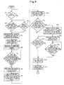
- FIGS. 4 to 6 are flow charts for splicing control.
- a web (strip) W continuously supplied from a feeding apparatus (strip continuous supply apparatus) 1, undergoes various printings while passing through printing units 2. Then, the web W is heated and dried when passed through a dryer 3. Then, the web W is cooled when passed through a cooling device 4. Then, when passing through a web path device 5 and a drag device 6, the web W is subjected to tension control or a change in direction. Then, the web W is cut to a predetermined shape and folded by a folder 7.
- a turret arm 11 has a central portion journaled by an apparatus body 10.
- a new web roll 12 and an old web roll 13 are mounted on both ends of the turret arm 11.
- the feeding apparatus 1 serves as a so-called automatic splicing apparatus. The state shown in FIG.
- the turret arm 11, as shown in FIG. 3, is turned by a turret arm turning motor (turret arm drive device) 14, and its turning angle is detected by a turret arm turning motor rotary encoder 15.
- a predrive device for drivingly rotating the new and old web rolls 12 and 13 is incorporated in the turret arm 11.
- the surface speed of the newweb roll 12, which has been moved to the splicing standby position, is accelerated beforehand by the predrive device until it becomes equal to the travel speed of the web W.
- a new web roll drive motor 16 is provided as the predrive device for driving the new web roll 12, and the rotational speed of the new web roll drive motor 16 is detected by a new web roll drive motor rotary encoder 17.
- the unwinding speed of the old web roll 13 is detected by an old web roll unwinding speed measuring rotary encoder 18.
- the apparatus body 10 is provided with a splicing apparatus 20 such that the splicing apparatus 20 can be pivoted by a splicing apparatus moving air cylinder 29.
- the splicing apparatus 20 is pivotable, with respect to the new web roll 12 moved to the splicing standby position, from a release position indicated by double-dotted chain lines in FIG. 1 to a contact position indicated by solid lines in FIG. 1.
- the web W unwound from the old web roll 13 passes through a clearance between the new web roll 12 and the splicing apparatus 20, and is paid out toward the printing units 2 past a plurality of rolls 22 and 23.
- the splicing apparatus 20 is provided with a fixed roll 24 for guiding the web W, and is also provided with a press-contact roller 25 and a cutter 26 such that the press-contact roller 25 and the cutter 26 can advance and retreat. As shown in FIG. 3, the press-contact roller 25 is driven by a press-contact roller drive air cylinder 27, and the cutter 26 is driven by a cutter air cylinder 28.
- the splicing apparatus 20 is mounted with a glue position detection sensor 31 for detecting a double-coated adhesive tape 30 (see FIG. 1) located at the front end of the web of the new web roll 12.
- the apparatus body 10 is also mounted with a new web roll stop position detection sensor (new web roll detection device) 32, and a web roll diameter measuring distance meter (distance measuring device) 33.
- the new web roll stop position detection sensor 32 is provided, in a direction intersecting the transport path of the new web roll 12 transported by the turret arm 11, to detect the outside diameter of the new web roll 12 at the splicing standby position.
- a transmission type photosensor or the like is adopted as the new web roll stop position detection sensor 32.
- the web roll diameter measuring distance meter 33 is provided at a position, where the distance meter 33 is opposed to the circumferential surface of the new web roll 12 when the new web roll 12 stops at the diameter measuring position, to measure the distance to the circumferential surface of the new web roll 12 by use of an ultrasonic wave or light (laser).
- the turret arm turning motor 14, the new web roll drive motor 16, the press-contact roller drive air cylinder 27, the cutter air cylinder 28, and the splicing apparatus moving air cylinder 29 are drivingly controlled by a control device 40.
- the control device 40 comprises CPU, ROM, and RAM, and also includes a new web roll diameter measuring position memory, a new web roll diameter memory, a turret arm width memory, a new web roll splicing standby position memory, an old web roll unwinding speed memory, a splicing time point new web roll drive motor rotational speed memory, a turret arm operating position memory, and a glue position detecting black tape detection internal timer.
- These devices, these memories, input/output devices 41a to 41i, and interfaces 42a, 42b are connected together by a bus-line BUS.
- An input device 35 such as a ready button, a manual splicing start button, or a key board, a display device 36, such as CRT or a display, and an output device 37, such as a printer or a floppy disk (registered trademark) drive, are connected to the input/output device 41a.
- the web roll diameter measuring distance meter 33 is connected to the input/output device 41b via an A/D converter 43.
- the glue position detection sensor 31 and the new web roll stop position detection sensor 32 are connected to the input/output device 41c.
- the (electromagnetic valve of) press-contact roller drive air cylinder 27, the (electromagnetic valve of) cutter air cylinder 28, and the (electromagnetic valve of) splicing apparatus moving air cylinder 29 are connected to the input/output device 41d.
- the old web roll unwinding speed measuring rotary encoder 18 is connected to the input/output device 41e via an A/D converter 44 and an F/V converter 45.
- the turret arm turning motor 14 is connected to the input/output device 41f via a turret arm turning motor-motor driver 46.
- the turret arm turning motor rotary encoder 15 is connected to the input/output device 41g via a turret arm turning position detection counter 47.
- a detection signal (clock pulse) of the turret arm turning motor rotary encoder 15 is inputted into the turret arm turning motor-motor driver 46.
- the new web roll drive motor 16 is connected to the input/output device 41h via a new web roll drive motor-motor driver 48.
- the new web roll drive motor rotary encoder 17 is connected to the input/output device 41i via an A/D converter 49 and an F/V converter 50.
- a residual paper length meter 34 is connected to the interfaces 42a, 42b.
- the residual paper length meter 34 is a computing device which always monitors the residual paper length of the old web roll 13, calculates howmanyminutes are left until splicing becomes necessary if the web is unwound at the current web travel speed, and outputs a splicing preparation start signal when the remaining time is less than the make-ready time. Its concrete features were already rendered publicly known by Japanese Utility Model Registration No. 2568743. Thus, its detailed explanation is omitted herein.
- the turret arm 11 is turned by the turret arm turning motor 14 and stopped thereby at the diameter measuring position of the new web roll 12.
- the distance (L1) to the circumferential surface of the new web roll 12 is measured by the web roll diameter measuring distance meter 33.
- the angle of rotation of the turret arm 11 from its reference position made until the turret arm 11 sets the new web roll 12 at the splicing standbyposition is found from the diameter (d1) of the new web roll 12 measured above.
- the turret arum 11 is rotated through this rotation angle by the turret arm turning motor 14 to set the newweb roll 12 at the splicing standby position.
- Step P1 it is determined whether the ready button for entering into splicing control is ON. If the ready button is ON, it is determined in Step P2 whether the splicing preparation start signal from the residual paper length meter 34 is ON. If the splicing preparation start signal is ON, the new web roll diameter measuring position is read from the new web roll diameter measuring position memory in Step P3. Even if the splicing preparation start signal is not ON in Step P2, the program proceeds to Step P3, if the manual splicing start button is ON in Step P4.
- Step P5 the turret arm turning motor 14 is driven for normal rotation, and in Step P6, the value of the turret arm turning position detection counter 47 is read. Then, in Step P7, it is determined whether the value of the turret arm turning position detection counter 47 is consistent with the new web roll diameter measuring position read from the new web roll diameter measuring position memory.
- Step P7 an output from the web roll diameter measuring distance meter 33 is read in Step P8. Also, in Step P9, the diameter of the new web roll is computed from the output of the web roll diameter measuring distance meter 33, and is stored in the new web roll diameter memory.
- Step P10 the value of the width of the turret arm 11 is read from the turret arm width memory.
- Step P11 it is determined whether the computed diameter of the new web roll is greater than the value of the width of the turret arm 11 read from the turret arm width memory. If the answer is YES, the program proceeds to Step P12, determining whether the new web roll stop position detection sensor 32 is ON. If ON, the turret arm turning motor 14 is stopped in Step P13.
- Step P11 If the computed diameter of the new web roll is found in Step P11 to be smaller than the value of the width of the turret arm 11, the splicing standby position of the new web roll 12 is computed from the computed diameter of the newweb roll in Step P14, where the computed result is stored in the new web roll splicing standby position memory. Then, in Step P15, the value of the turret arm turning position detection counter 47 is read. Then, in Step P16, it is determined whether the value of the turret arm turning position detection counter 47 is consistent with the computed splicing standby position of the new web roll 12. If consistency is found, the program shifts to Step P13.
- Step P17 the splicing apparatus moving air cylinder 29 is turned on, whereafter in Step P18, the diameter of the new web roll is read from the new web roll diameter memory. Then, in Step P19, an output frequency from the old web roll unwinding speed measuring rotary encoder 18 is read.
- Step P20 the unwinding speed of the old web roll 13 is computed from the read output frequency of the old web roll unwinding speed measuring rotary encoder 18, and is stored in the old web roll unwinding speed memory.
- Step P21 the rotational speed of the new web roll 12 (the rotational speed of the new web roll drive motor 16) at the time of splicing is computed from the read diameter of the new web roll and the computed unwinding speed of the old web roll 13, and is stored in the splicing time point new web roll drive motor rotational speed memory.
- Step P22 an output is issued to the new web roll drive motor 16 so that the new web roll drive motor 16 is driven at the computed rotational speed.
- Step P23 an output frequency from the new web roll drive motor rotary encoder 17 is read.
- Step P24 the current rotational speed of the new web roll drive motor 16 is computed from the read output frequency from the new web roll drive motor rotary encoder 17.
- Step P25 it is determined whether the current rotational speed of the new web roll drive motor 16 is consistent with the rotational speed outputted to the new web roll drive motor 16. If the answer is affirmative, counting of the glue position detecting black tape detection internal counter is started in Step P26.
- Step P27 determinations are made in Step P27 as to whether the glue position detection sensor 31 is ON, in Step P28 as to whether the manual splicing start button is ON, and in Step P29 as to whether the splicing preparation start signal from the residual paper length meter 34 is ON. If ON in these steps, the press-contact roller drive air cylinder 27 is turned on in Step P30. If the glue position detection sensor 31 is not ON in Step P27, and if the glue position detecting black tape detection internal timer is found to count up in Step P31, the control device 40 makes a determination "Abnormal", thus stopping the operation of the printing press in Step P32.
- Step P33 the cutter air cylinder 28 is turned on to cut the web W of the old web roll 13.
- the press-contact roller drive air cylinder 27, the cutter air cylinder 28, and the splicing apparatus moving air cylinder 29 are turned off in Steps P34 to P36, completing the splicing actions.
- Step P37 the operating position of the turret arm 11 is read from the turret arm operating position memory.
- Step P38 the turret arm turning motor 14 is driven for reverse rotation.
- Step P39 the value of the turret arm turning position detection counter 47 is read.
- Step P40 it is determined whether the read value of the turret arm turning position detection counter 47 is consistent with the operating position of the turret arm 11 read from the turret arm operating position memory. If consistency is found, the turret arm turning motor 14 is stopped in Step P41 to terminate splicing control.
- the feeding apparatus is equipped with the following web roll diameter measuring distance meter 33, and the following control device 40:
- the diameter of the new web roll 12 can be determined accurately without influence from the external dimension of the turret arm. Moreover, based on this value, the turret arm turning motor 14 is controlled, whereby the new web roll 12 can be set at the splicing standby position accurately. Consequently, high precision splicing control can be performed.
- the feeding apparatus is also provided with the turret arm turning motor rotary encoder 15 for detecting the rotation angle of the turret arm 11.
- the control device 40 drives the turret arm turning motor 14, and stops the turret arm turning motor 14 in accordance with the output from the turret arm turning motor rotary encoder 15 to move the new web roll 12 to the splicing standby position.
- the new web roll 12 can be set at the splicing standby position more precisely.
- the feeding apparatus is also provided with the turret arm turning motor rotary encoder 15 for detecting the rotation angle of the turret arm 11.
- the control device 40 drives the turret arm turning motor 14, and stops the turret arm turning motor 14 in accordance with the output from the turret arm turning motor rotary encoder 15 to move the new web roll 12 to the diameter measuring position. Hence, the new web roll 12 can be moved to the diameter measuring position more precisely.
- the feeding apparatus is also provided with the new web roll stop position detection sensor 32. If the measured diameter of the new web roll 12 is larger than a certain value, the control device 40 drives the turret arm turning motor 14, and stops the turret arm turning motor 14 in accordance with the output from the new web roll stop position detection sensor 32 to move the new web roll 12 to the splicing standby position. Hence, if the diameter of the new web roll 12 is greater than the width of the turret arm 11, the new web roll 12 can be precisely moved to the splicing standby position by simple control, without any trouble (without the conventional erroneous detection of the outside diameter of the turret arm 11 as the outside diameter of the new web roll 12).
- the strip continuous supply apparatus and method according to the present invention can be applied not only to an offset rotary press, but also as aweb material supply device in a machine, such as a corrugator or a laminator.
- a machine such as a corrugator or a laminator.
Landscapes
- Replacement Of Web Rolls (AREA)
- Controlling Rewinding, Feeding, Winding, Or Abnormalities Of Webs (AREA)
- Containers And Plastic Fillers For Packaging (AREA)
- Preliminary Treatment Of Fibers (AREA)
- Supplying Of Containers To The Packaging Station (AREA)
Applications Claiming Priority (2)
| Application Number | Priority Date | Filing Date | Title |
|---|---|---|---|
| JP2003335235A JP4014551B2 (ja) | 2003-09-26 | 2003-09-26 | 帯状体連続供給装置及び方法 |
| JP2003335235 | 2003-09-26 |
Publications (3)
| Publication Number | Publication Date |
|---|---|
| EP1518804A2 true EP1518804A2 (de) | 2005-03-30 |
| EP1518804A3 EP1518804A3 (de) | 2005-09-28 |
| EP1518804B1 EP1518804B1 (de) | 2008-08-13 |
Family
ID=34191522
Family Applications (1)
| Application Number | Title | Priority Date | Filing Date |
|---|---|---|---|
| EP04022437A Expired - Lifetime EP1518804B1 (de) | 2003-09-26 | 2004-09-21 | Kontinuierliche Bahnzuführvorrichtung und Verfahren |
Country Status (7)
| Country | Link |
|---|---|
| US (1) | US7156340B2 (de) |
| EP (1) | EP1518804B1 (de) |
| JP (1) | JP4014551B2 (de) |
| CN (1) | CN1600543B (de) |
| AT (1) | ATE404482T1 (de) |
| DE (1) | DE602004015693D1 (de) |
| ES (1) | ES2312898T3 (de) |
Cited By (3)
| Publication number | Priority date | Publication date | Assignee | Title |
|---|---|---|---|---|
| CN106006133A (zh) * | 2016-06-30 | 2016-10-12 | 河南中烟工业有限责任公司 | 一种卷烟包装机条透明纸自动拼接装置及方法 |
| CN112477393A (zh) * | 2020-10-21 | 2021-03-12 | 镇江市海络数码科技有限公司 | 一种高性能可调节热转印升华设备 |
| EP3699128A4 (de) * | 2017-11-30 | 2022-01-19 | Zuiko Corporation | Blattzuführvorrichtung und blattzuführverfahren |
Families Citing this family (23)
| Publication number | Priority date | Publication date | Assignee | Title |
|---|---|---|---|---|
| DE102005001406B4 (de) * | 2005-01-12 | 2021-05-27 | Deere & Company | Hüllmittelanzeigevorrichtung |
| JP4407631B2 (ja) * | 2005-12-15 | 2010-02-03 | ソニー株式会社 | ロール紙給紙機構、ロール紙給紙カセット、及び画像形成装置 |
| JP2007320733A (ja) * | 2006-06-02 | 2007-12-13 | Komori Corp | 帯状体連続供給方法及び装置 |
| JP2008000918A (ja) * | 2006-06-20 | 2008-01-10 | Mitsubishi Heavy Ind Ltd | 給紙装置 |
| EP2062841B1 (de) * | 2007-11-23 | 2013-02-13 | Goss Contiweb B.V. | Vorrichtung zum Aufbringen einer Papierbahn auf eine Papierrolle und entsprechender Rollenwechsler |
| US9241714B2 (en) | 2011-04-29 | 2016-01-26 | Ethicon Endo-Surgery, Inc. | Tissue thickness compensator and method for making the same |
| JP2013006664A (ja) * | 2011-06-24 | 2013-01-10 | Sumitomo Chemical Co Ltd | フィルム残径検出装置、搬送装置および貼合システム |
| CN102794978B (zh) * | 2012-08-24 | 2015-04-08 | 宁波欣达印刷机器有限公司 | 高速卷筒料印刷机的自动裁切接料装置 |
| CN103482329B (zh) * | 2013-09-10 | 2016-01-06 | 陕西北人印刷机械有限责任公司 | 一种印刷机上的自动上卸料升降装置 |
| CN104495456A (zh) * | 2014-11-11 | 2015-04-08 | 苏州东昇机电科技有限公司 | 在线收卷分切机上的自动换卷机构 |
| CN104609230B (zh) * | 2015-01-19 | 2019-04-05 | 宁波欣达印刷机器有限公司 | 一种用于卷筒料加工的多功能收卷装置 |
| US10457512B2 (en) | 2016-09-19 | 2019-10-29 | New Era Converting Machinery, Inc. | Automatic lapless butt material splice |
| CN106829609B (zh) * | 2017-01-06 | 2018-07-24 | 佛山市宾宏设备有限公司 | 一种医用纱布自动生产线的钡片下料机构 |
| CN107117484B (zh) * | 2017-05-06 | 2018-12-11 | 南京航空航天大学 | 一种自动切换的卷棉装置及操作方法 |
| US11420838B2 (en) | 2017-11-30 | 2022-08-23 | Zuiko Corporation | Sheet supply device and sheet supply method |
| BR112020010600A2 (pt) * | 2017-11-30 | 2020-11-10 | Zuiko Corporation | dispositivo de fornecimento de folhas e método de fornecimento de folhas |
| EP3699126A4 (de) | 2017-11-30 | 2022-03-02 | Zuiko Corporation | Blattzuführvorrichtung und blattzuführverfahren |
| CN107973164B (zh) * | 2018-01-08 | 2024-06-11 | 东莞市浩星自动化设备有限公司 | 一种全自动模材接料机 |
| CN108341297A (zh) * | 2018-01-26 | 2018-07-31 | 徐雪华 | 三辊式开料机自动上料控制系统 |
| US20210379783A1 (en) * | 2018-10-15 | 2021-12-09 | 3M Innovative Properties Company | Slitter director for automated control of slit roll generation from manufactured web |
| CN111674999A (zh) * | 2020-07-03 | 2020-09-18 | 运城制版印刷机械制造有限公司 | 超声波自动裁切凹版印刷机 |
| KR102821499B1 (ko) * | 2024-08-16 | 2025-06-17 | (주)지우텍 | 언와인더 장치용 터렛 브레이크 |
| KR102821498B1 (ko) * | 2024-08-16 | 2025-06-17 | (주)지우텍 | 오토 척킹 언와인더 장치 |
Family Cites Families (8)
| Publication number | Priority date | Publication date | Assignee | Title |
|---|---|---|---|---|
| NL121850C (de) * | 1963-04-10 | |||
| US3825201A (en) * | 1973-05-22 | 1974-07-23 | F Osta | Device for controlling the launching of a reel of web in an unwinder with automatic reel change |
| JP2568743Y2 (ja) | 1992-07-09 | 1998-04-15 | 株式会社小森コーポレーション | 残紙長計 |
| JP3108035B2 (ja) * | 1997-05-28 | 2000-11-13 | 株式会社東京機械製作所 | 自動紙継方法及び装置 |
| US6113753A (en) * | 1999-03-23 | 2000-09-05 | Flextor, Inc. | Systems and methods for making a magnetic recording medium on a flexible metal substrate |
| US6264417B1 (en) * | 1999-04-21 | 2001-07-24 | Eastman Kodak Company | Flexible roll chucking assemblage and method |
| JP3427355B2 (ja) * | 2000-12-14 | 2003-07-14 | 株式会社東京機械製作所 | 紙継ぎ装置における巻取体の駆動装置 |
| JP4369073B2 (ja) | 2001-04-13 | 2009-11-18 | 株式会社小森コーポレーション | 帯状体連続供給装置の制御方法及びその装置 |
-
2003
- 2003-09-26 JP JP2003335235A patent/JP4014551B2/ja not_active Expired - Fee Related
-
2004
- 2004-09-21 AT AT04022437T patent/ATE404482T1/de not_active IP Right Cessation
- 2004-09-21 EP EP04022437A patent/EP1518804B1/de not_active Expired - Lifetime
- 2004-09-21 ES ES04022437T patent/ES2312898T3/es not_active Expired - Lifetime
- 2004-09-21 DE DE602004015693T patent/DE602004015693D1/de not_active Expired - Lifetime
- 2004-09-23 US US10/947,179 patent/US7156340B2/en not_active Expired - Lifetime
- 2004-09-24 CN CN2004100117079A patent/CN1600543B/zh not_active Expired - Fee Related
Cited By (3)
| Publication number | Priority date | Publication date | Assignee | Title |
|---|---|---|---|---|
| CN106006133A (zh) * | 2016-06-30 | 2016-10-12 | 河南中烟工业有限责任公司 | 一种卷烟包装机条透明纸自动拼接装置及方法 |
| EP3699128A4 (de) * | 2017-11-30 | 2022-01-19 | Zuiko Corporation | Blattzuführvorrichtung und blattzuführverfahren |
| CN112477393A (zh) * | 2020-10-21 | 2021-03-12 | 镇江市海络数码科技有限公司 | 一种高性能可调节热转印升华设备 |
Also Published As
| Publication number | Publication date |
|---|---|
| CN1600543A (zh) | 2005-03-30 |
| JP4014551B2 (ja) | 2007-11-28 |
| CN1600543B (zh) | 2010-12-08 |
| EP1518804B1 (de) | 2008-08-13 |
| US20050077417A1 (en) | 2005-04-14 |
| JP2005096968A (ja) | 2005-04-14 |
| US7156340B2 (en) | 2007-01-02 |
| ATE404482T1 (de) | 2008-08-15 |
| ES2312898T3 (es) | 2009-03-01 |
| EP1518804A3 (de) | 2005-09-28 |
| DE602004015693D1 (de) | 2008-09-25 |
Similar Documents
| Publication | Publication Date | Title |
|---|---|---|
| EP1518804B1 (de) | Kontinuierliche Bahnzuführvorrichtung und Verfahren | |
| US20070278341A1 (en) | Strip continuous supply method and apparatus | |
| US5253819A (en) | Speed match splicing method and apparatus | |
| US6695027B2 (en) | Speed matching system for a web splicer mechanism in a web-fed printing press or the like | |
| US20100080643A1 (en) | Printing press and operating method for the same | |
| US5325306A (en) | System for informing paper shift in apparatus for producing corrugated paper boards | |
| US7647845B2 (en) | Method and device for determining the web tension or the web tensile force in a printing substrate web | |
| US6006669A (en) | Apparatus for affixing removable notes to a moving web | |
| US6606944B1 (en) | Device and method for determining a signature lap | |
| US5335870A (en) | Flying paster | |
| JP2568743Y2 (ja) | 残紙長計 | |
| US20070145178A1 (en) | Method and device for threading a web | |
| US20040104256A1 (en) | Devices for drawing in a web of material | |
| JPH06171067A (ja) | 印刷機の給紙装置 | |
| GB2388588A (en) | Web feeding in printing and laminating apparatus | |
| JPH01150666A (ja) | 輪転機のリールの周速・巻径検出法 | |
| JP3283353B2 (ja) | 紙継ぎ制御方法及びその装置 | |
| JP2002003032A (ja) | ウェブ送給装置 | |
| JPH05286615A (ja) | オートペースタ制御装置 | |
| JP2860835B2 (ja) | 自動紙継装置におけるプリドライブ機構 | |
| JPH0558543A (ja) | ウエブの補修方法及び補修装置 | |
| JP3745079B2 (ja) | 紙継ぎ制御方法及びその装置 | |
| JPH07205090A (ja) | シートの不良個所削除用作業台 | |
| JPH066129Y2 (ja) | 紙継装置におけるプリドライブ機構 | |
| JPH0237076Y2 (de) |
Legal Events
| Date | Code | Title | Description |
|---|---|---|---|
| PUAI | Public reference made under article 153(3) epc to a published international application that has entered the european phase |
Free format text: ORIGINAL CODE: 0009012 |
|
| AK | Designated contracting states |
Kind code of ref document: A2 Designated state(s): AT BE BG CH CY CZ DE DK EE ES FI FR GB GR HU IE IT LI LU MC NL PL PT RO SE SI SK TR |
|
| AX | Request for extension of the european patent |
Extension state: AL HR LT LV MK |
|
| PUAL | Search report despatched |
Free format text: ORIGINAL CODE: 0009013 |
|
| AK | Designated contracting states |
Kind code of ref document: A3 Designated state(s): AT BE BG CH CY CZ DE DK EE ES FI FR GB GR HU IE IT LI LU MC NL PL PT RO SE SI SK TR |
|
| AX | Request for extension of the european patent |
Extension state: AL HR LT LV MK |
|
| 17P | Request for examination filed |
Effective date: 20051031 |
|
| AKX | Designation fees paid |
Designated state(s): AT BE BG CH CY CZ DE DK EE ES FI FR GB GR HU IE IT LI LU MC NL PL PT RO SE SI SK TR |
|
| GRAP | Despatch of communication of intention to grant a patent |
Free format text: ORIGINAL CODE: EPIDOSNIGR1 |
|
| GRAS | Grant fee paid |
Free format text: ORIGINAL CODE: EPIDOSNIGR3 |
|
| GRAA | (expected) grant |
Free format text: ORIGINAL CODE: 0009210 |
|
| AK | Designated contracting states |
Kind code of ref document: B1 Designated state(s): AT BE BG CH CY CZ DE DK EE ES FI FR GB GR HU IE IT LI LU MC NL PL PT RO SE SI SK TR |
|
| REG | Reference to a national code |
Ref country code: GB Ref legal event code: FG4D |
|
| REG | Reference to a national code |
Ref country code: CH Ref legal event code: EP |
|
| REG | Reference to a national code |
Ref country code: IE Ref legal event code: FG4D |
|
| REF | Corresponds to: |
Ref document number: 602004015693 Country of ref document: DE Date of ref document: 20080925 Kind code of ref document: P |
|
| REG | Reference to a national code |
Ref country code: SE Ref legal event code: TRGR |
|
| REG | Reference to a national code |
Ref country code: CH Ref legal event code: NV Representative=s name: R. A. EGLI & CO. PATENTANWAELTE |
|
| PG25 | Lapsed in a contracting state [announced via postgrant information from national office to epo] |
Ref country code: FI Free format text: LAPSE BECAUSE OF FAILURE TO SUBMIT A TRANSLATION OF THE DESCRIPTION OR TO PAY THE FEE WITHIN THE PRESCRIBED TIME-LIMIT Effective date: 20080813 Ref country code: AT Free format text: LAPSE BECAUSE OF FAILURE TO SUBMIT A TRANSLATION OF THE DESCRIPTION OR TO PAY THE FEE WITHIN THE PRESCRIBED TIME-LIMIT Effective date: 20080813 Ref country code: SI Free format text: LAPSE BECAUSE OF FAILURE TO SUBMIT A TRANSLATION OF THE DESCRIPTION OR TO PAY THE FEE WITHIN THE PRESCRIBED TIME-LIMIT Effective date: 20080813 |
|
| REG | Reference to a national code |
Ref country code: ES Ref legal event code: FG2A Ref document number: 2312898 Country of ref document: ES Kind code of ref document: T3 |
|
| PG25 | Lapsed in a contracting state [announced via postgrant information from national office to epo] |
Ref country code: BE Free format text: LAPSE BECAUSE OF FAILURE TO SUBMIT A TRANSLATION OF THE DESCRIPTION OR TO PAY THE FEE WITHIN THE PRESCRIBED TIME-LIMIT Effective date: 20080813 |
|
| PG25 | Lapsed in a contracting state [announced via postgrant information from national office to epo] |
Ref country code: DK Free format text: LAPSE BECAUSE OF FAILURE TO SUBMIT A TRANSLATION OF THE DESCRIPTION OR TO PAY THE FEE WITHIN THE PRESCRIBED TIME-LIMIT Effective date: 20080813 Ref country code: MC Free format text: LAPSE BECAUSE OF NON-PAYMENT OF DUE FEES Effective date: 20080930 Ref country code: BG Free format text: LAPSE BECAUSE OF FAILURE TO SUBMIT A TRANSLATION OF THE DESCRIPTION OR TO PAY THE FEE WITHIN THE PRESCRIBED TIME-LIMIT Effective date: 20081113 |
|
| PG25 | Lapsed in a contracting state [announced via postgrant information from national office to epo] |
Ref country code: RO Free format text: LAPSE BECAUSE OF FAILURE TO SUBMIT A TRANSLATION OF THE DESCRIPTION OR TO PAY THE FEE WITHIN THE PRESCRIBED TIME-LIMIT Effective date: 20080813 Ref country code: SK Free format text: LAPSE BECAUSE OF FAILURE TO SUBMIT A TRANSLATION OF THE DESCRIPTION OR TO PAY THE FEE WITHIN THE PRESCRIBED TIME-LIMIT Effective date: 20080813 Ref country code: CZ Free format text: LAPSE BECAUSE OF FAILURE TO SUBMIT A TRANSLATION OF THE DESCRIPTION OR TO PAY THE FEE WITHIN THE PRESCRIBED TIME-LIMIT Effective date: 20080813 Ref country code: PT Free format text: LAPSE BECAUSE OF FAILURE TO SUBMIT A TRANSLATION OF THE DESCRIPTION OR TO PAY THE FEE WITHIN THE PRESCRIBED TIME-LIMIT Effective date: 20090113 |
|
| PLBE | No opposition filed within time limit |
Free format text: ORIGINAL CODE: 0009261 |
|
| STAA | Information on the status of an ep patent application or granted ep patent |
Free format text: STATUS: NO OPPOSITION FILED WITHIN TIME LIMIT |
|
| 26N | No opposition filed |
Effective date: 20090514 |
|
| PG25 | Lapsed in a contracting state [announced via postgrant information from national office to epo] |
Ref country code: IE Free format text: LAPSE BECAUSE OF NON-PAYMENT OF DUE FEES Effective date: 20080921 Ref country code: EE Free format text: LAPSE BECAUSE OF FAILURE TO SUBMIT A TRANSLATION OF THE DESCRIPTION OR TO PAY THE FEE WITHIN THE PRESCRIBED TIME-LIMIT Effective date: 20080813 |
|
| PGFP | Annual fee paid to national office [announced via postgrant information from national office to epo] |
Ref country code: ES Payment date: 20090929 Year of fee payment: 6 |
|
| PGFP | Annual fee paid to national office [announced via postgrant information from national office to epo] |
Ref country code: GB Payment date: 20090916 Year of fee payment: 6 Ref country code: NL Payment date: 20090915 Year of fee payment: 6 Ref country code: SE Payment date: 20090910 Year of fee payment: 6 |
|
| PGFP | Annual fee paid to national office [announced via postgrant information from national office to epo] |
Ref country code: FR Payment date: 20091012 Year of fee payment: 6 Ref country code: IT Payment date: 20090918 Year of fee payment: 6 |
|
| PG25 | Lapsed in a contracting state [announced via postgrant information from national office to epo] |
Ref country code: PL Free format text: LAPSE BECAUSE OF FAILURE TO SUBMIT A TRANSLATION OF THE DESCRIPTION OR TO PAY THE FEE WITHIN THE PRESCRIBED TIME-LIMIT Effective date: 20080813 |
|
| PG25 | Lapsed in a contracting state [announced via postgrant information from national office to epo] |
Ref country code: CY Free format text: LAPSE BECAUSE OF FAILURE TO SUBMIT A TRANSLATION OF THE DESCRIPTION OR TO PAY THE FEE WITHIN THE PRESCRIBED TIME-LIMIT Effective date: 20080813 Ref country code: LU Free format text: LAPSE BECAUSE OF NON-PAYMENT OF DUE FEES Effective date: 20080921 Ref country code: HU Free format text: LAPSE BECAUSE OF FAILURE TO SUBMIT A TRANSLATION OF THE DESCRIPTION OR TO PAY THE FEE WITHIN THE PRESCRIBED TIME-LIMIT Effective date: 20090214 |
|
| PG25 | Lapsed in a contracting state [announced via postgrant information from national office to epo] |
Ref country code: TR Free format text: LAPSE BECAUSE OF FAILURE TO SUBMIT A TRANSLATION OF THE DESCRIPTION OR TO PAY THE FEE WITHIN THE PRESCRIBED TIME-LIMIT Effective date: 20080813 |
|
| PG25 | Lapsed in a contracting state [announced via postgrant information from national office to epo] |
Ref country code: GR Free format text: LAPSE BECAUSE OF FAILURE TO SUBMIT A TRANSLATION OF THE DESCRIPTION OR TO PAY THE FEE WITHIN THE PRESCRIBED TIME-LIMIT Effective date: 20081114 |
|
| REG | Reference to a national code |
Ref country code: NL Ref legal event code: V1 Effective date: 20110401 |
|
| REG | Reference to a national code |
Ref country code: SE Ref legal event code: EUG |
|
| GBPC | Gb: european patent ceased through non-payment of renewal fee |
Effective date: 20100921 |
|
| PG25 | Lapsed in a contracting state [announced via postgrant information from national office to epo] |
Ref country code: IT Free format text: LAPSE BECAUSE OF NON-PAYMENT OF DUE FEES Effective date: 20100921 |
|
| REG | Reference to a national code |
Ref country code: FR Ref legal event code: ST Effective date: 20110531 |
|
| PG25 | Lapsed in a contracting state [announced via postgrant information from national office to epo] |
Ref country code: FR Free format text: LAPSE BECAUSE OF NON-PAYMENT OF DUE FEES Effective date: 20100930 |
|
| PG25 | Lapsed in a contracting state [announced via postgrant information from national office to epo] |
Ref country code: NL Free format text: LAPSE BECAUSE OF NON-PAYMENT OF DUE FEES Effective date: 20110401 Ref country code: GB Free format text: LAPSE BECAUSE OF NON-PAYMENT OF DUE FEES Effective date: 20100921 |
|
| REG | Reference to a national code |
Ref country code: ES Ref legal event code: FD2A Effective date: 20111019 |
|
| PGFP | Annual fee paid to national office [announced via postgrant information from national office to epo] |
Ref country code: CH Payment date: 20110913 Year of fee payment: 8 |
|
| PG25 | Lapsed in a contracting state [announced via postgrant information from national office to epo] |
Ref country code: ES Free format text: LAPSE BECAUSE OF NON-PAYMENT OF DUE FEES Effective date: 20100922 |
|
| PG25 | Lapsed in a contracting state [announced via postgrant information from national office to epo] |
Ref country code: SE Free format text: LAPSE BECAUSE OF NON-PAYMENT OF DUE FEES Effective date: 20100922 |
|
| REG | Reference to a national code |
Ref country code: CH Ref legal event code: PL |
|
| PG25 | Lapsed in a contracting state [announced via postgrant information from national office to epo] |
Ref country code: CH Free format text: LAPSE BECAUSE OF NON-PAYMENT OF DUE FEES Effective date: 20130930 Ref country code: LI Free format text: LAPSE BECAUSE OF NON-PAYMENT OF DUE FEES Effective date: 20130930 |
|
| PGFP | Annual fee paid to national office [announced via postgrant information from national office to epo] |
Ref country code: DE Payment date: 20150916 Year of fee payment: 12 |
|
| REG | Reference to a national code |
Ref country code: DE Ref legal event code: R119 Ref document number: 602004015693 Country of ref document: DE |
|
| PG25 | Lapsed in a contracting state [announced via postgrant information from national office to epo] |
Ref country code: DE Free format text: LAPSE BECAUSE OF NON-PAYMENT OF DUE FEES Effective date: 20170401 |