EP1518964B2 - Oberflächenentwässerungseinrichtung - Google Patents
Oberflächenentwässerungseinrichtung Download PDFInfo
- Publication number
- EP1518964B2 EP1518964B2 EP04255634.0A EP04255634A EP1518964B2 EP 1518964 B2 EP1518964 B2 EP 1518964B2 EP 04255634 A EP04255634 A EP 04255634A EP 1518964 B2 EP1518964 B2 EP 1518964B2
- Authority
- EP
- European Patent Office
- Prior art keywords
- former
- inlet
- inlet former
- drain
- channel
- Prior art date
- Legal status (The legal status is an assumption and is not a legal conclusion. Google has not performed a legal analysis and makes no representation as to the accuracy of the status listed.)
- Expired - Lifetime
Links
- 239000000463 material Substances 0.000 claims description 24
- 239000007788 liquid Substances 0.000 claims description 11
- 239000012530 fluid Substances 0.000 claims description 4
- 239000011800 void material Substances 0.000 description 18
- 238000009434 installation Methods 0.000 description 14
- XLYOFNOQVPJJNP-UHFFFAOYSA-N water Substances O XLYOFNOQVPJJNP-UHFFFAOYSA-N 0.000 description 8
- 229910000831 Steel Inorganic materials 0.000 description 3
- 239000004746 geotextile Substances 0.000 description 3
- 239000010959 steel Substances 0.000 description 3
- XEEYBQQBJWHFJM-UHFFFAOYSA-N Iron Chemical compound [Fe] XEEYBQQBJWHFJM-UHFFFAOYSA-N 0.000 description 2
- 239000002184 metal Substances 0.000 description 2
- 229910052751 metal Inorganic materials 0.000 description 2
- 229920003023 plastic Polymers 0.000 description 2
- 239000004033 plastic Substances 0.000 description 2
- 239000007787 solid Substances 0.000 description 2
- 239000010426 asphalt Substances 0.000 description 1
- 238000004140 cleaning Methods 0.000 description 1
- 238000010276 construction Methods 0.000 description 1
- 230000001419 dependent effect Effects 0.000 description 1
- ZZUFCTLCJUWOSV-UHFFFAOYSA-N furosemide Chemical compound C1=C(Cl)C(S(=O)(=O)N)=CC(C(O)=O)=C1NCC1=CC=CO1 ZZUFCTLCJUWOSV-UHFFFAOYSA-N 0.000 description 1
- 229910052742 iron Inorganic materials 0.000 description 1
- 238000004519 manufacturing process Methods 0.000 description 1
- 230000002787 reinforcement Effects 0.000 description 1
- 239000011343 solid material Substances 0.000 description 1
- 239000002352 surface water Substances 0.000 description 1
Images




Classifications
-
- E—FIXED CONSTRUCTIONS
- E03—WATER SUPPLY; SEWERAGE
- E03F—SEWERS; CESSPOOLS
- E03F3/00—Sewer pipe-line systems
- E03F3/04—Pipes or fittings specially adapted to sewers
- E03F3/046—Open sewage channels
-
- E—FIXED CONSTRUCTIONS
- E01—CONSTRUCTION OF ROADS, RAILWAYS, OR BRIDGES
- E01C—CONSTRUCTION OF, OR SURFACES FOR, ROADS, SPORTS GROUNDS, OR THE LIKE; MACHINES OR AUXILIARY TOOLS FOR CONSTRUCTION OR REPAIR
- E01C11/00—Details of pavings
- E01C11/22—Gutters; Kerbs ; Surface drainage of streets, roads or like traffic areas
- E01C11/224—Surface drainage of streets
- E01C11/227—Gutters; Channels ; Roof drainage discharge ducts set in sidewalks
-
- E—FIXED CONSTRUCTIONS
- E03—WATER SUPPLY; SEWERAGE
- E03F—SEWERS; CESSPOOLS
- E03F1/00—Methods, systems, or installations for draining-off sewage or storm water
- E03F1/002—Methods, systems, or installations for draining-off sewage or storm water with disposal into the ground, e.g. via dry wells
Definitions
- the present invention relates to surface drainage and in particular, linear and point surface drainage arrangements.
- Another known form of drainage system employs a substantially continuous linear slot in the drained surface to serve as the inlet. It is recognised that surface drainage systems employing linear slots are more efficient than those drainage arrangements possessing discrete inlets, as in general they provide a greater inlet area and minimise the volume of water (or other liquid) that can wash over the drained surface without being entrained by the inlet.
- US Patent US6000881 shows a linear drainage system of this type, as does GB-A-2311549 . Both of the systems described in these documents employ a large underground channel which has at its upper side a narrower throat portion defined by two walls extending upwardly to the surface to be drained, where they terminate to form a continuous slot drain in the surface.
- AU199878635 in the name of John Joseph Creighton discloses a surface drainage system comprised of a shallow channel that forms a gutter in a surface, and which is linked by spigots to a drain pipe embedded in the ground below.
- the present invention provides a discrete inlet former according to claim 1 and a linear surface drainage system according to claim 9. Further features are set out in the dependent claims.
- the cantilevered slabs of the conventional linear drainage systems are no longer present.
- the load of and on the surface material is borne principally by the bridge members as opposed to the inlet former or any underlying structure associated with the installed drainage system.
- the present invention provides a discrete inlet former which may, but need not be, used in conjunction with an underground drainage channel.
- the inlet former may be used, for example, to drain water (or other liquid) from a surface into any other form of underlying, manmade or even natural void.
- the or each transverse opening provides a continuous passage though the former from one side to the other, such that the material in which the former is embedded extends through the opening from one side of the former to the other to form the structural bridge.
- the inlet former will typically be formed in sections of easily manageable lengths which can be used alone, in combination but spaced apart, or butted against one another to form a substantially continuous slot inlet comprising multiple sections.
- the easily manageable lengths may consist of section lengths of 1 to 2 metres, however, if the site for the system has sufficient handling capabilities, longer lengths of section may be used.
- the inlet former may include one or more side inlet openings that allow liquid to drain into the inlet former from one or both of its sides.
- the inlet former prefferably comprises a filter mounted within the inlet slot to prevent the ingress of large solid objects that might cause a blockage in the inlet former or other elements of a drainage systems with which it is used.
- the invention provides a surface drainage installation comprising an inlet former as set forth above installed in a surface to be drained and a void underlying the inlet former into which fluid can drain through the former.
- the void may be provided by an underlying channel. Alternatively, it may simply be an area intended to catch and store drained liquid for later removal, e.g. by allowing the liquid to leach out from this area. Particularly where there is no channel used, it may be preferred that the void is filled with a high void material (i.e. a structural material having large, interconnecting voids within it).
- the invention also provides a drainage installation comprising an inlet former as set forth above installed in a surface to be drained at the bottom of a gully in the surface.
- the gully can be pre-formed or formed on site or otherwise.
- the installation may be formed at the base of a slip-formed channel located in the surface to be drained.
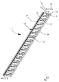
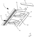
- the main structure of the inlet former 1 is provided by two side walls 2, 2', both of which are flanged at top edges and bottom edges to form outwardly extending lips 3, 3', 4, 4' respectively.
- the walls 2, 2' are spaced laterally from one another and joined by tubular cross-members 5. These tubular elements also form openings that extend through the inlet former from one lateral side to the other.
- the spaced walls define a longitudinal slot 6 designed, in use, to collect water from a surface in which the inlet former is installed.
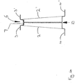
- the lower ends of the walls are spaced further from one another than the upper ends, so that the channel they define flares downwardly. This helps to prevent any solid material that enters through the slot becoming wedged in this channel.
- This filter serves to prevent large solid objects passing though the inlet former. It is designed to be removable through the slot at the upper end of the former for cleaning.
- the spaces within the former defined between the walls and the tubular cross-members serve as conduits through which liquid that drains into the slot can pass through the inlet former out of its lower end.
- Each of the former walls also has a series of side inlet openings 8 spaced along their length, between the tubular cross-members. These allow water to drain into the channel defined by the walls from either side of the inlet former.
- the walls of the inlet former 1, the tubular cross-members 5 and the filter member 6 may be formed of any of a number of appropriate materials including, for example sheet metal (e.g. steel), cast metal (e.g. iron), any other variety of plastics materials or a combination of these materials.
- the inlet former may be manufactured as a single section or as a number of separate components to be assembled post-manufacture.
- each wall of the former may be manufactured as a separate component formed integrally with a portion or complete ones of the tubular cross-members.
- the filter member 6 will normally be a separate component in order that it can be removed if desired.
- End caps 9 may be provided to seal the open ends defined by the space between the former walls. These also allow the length or effective length of the former to be adjusted depending on the site requirements.
- Fig.4 illustrates an alternative embodiment in which the passage through the former 1 provided by the tubular elements 5 may be interrupted by a vertical plate 10, creating two opposed, blind lateral openings having face to face contact, one opening to either side of the former.
- Fig. 5 shows a former 1 having a rolled edge 11, 11' which may be used when the former is for use with asphalt and/or block surfacing materials.
- a void is formed (e.g. excavated) in the ground in the area that is to be drained.
- the void in the ground is lined with a water permeable material, such as a geotextile material, that allows water to pass in a controlled fashion from within the void to the surrounding ground.
- the void itself is filled with a high void material 12.
- suitable materials include STORMCELLTM provided by Hydro International plc
- the inlet former 1 is embedded in the slab with its upper end level with the surface of the slab and its lower end opening into the high void material. In this manner a slot drain is formed in the surface, water draining from the surface through the inlet former into the high void material below.
- the rainwater When there is, for example, rainfall of high intensity, the rainwater will drain quickly through the slot 6 into the high void material 12 and then, over a period of time, soak away through the geotextile material into the surrounding ground.
- the geotextile material could be impermeable for deliberate water retention.
- the inlet former On installation, the inlet former is located above the underground void and secured in place by some suitable means.
- the broad flanges 2, 2' at the lower end of the former walls can be used to secure the former in place (alternatively, in place of such flanges, a series of broad feet might be provided).
- the surface slab material 13 e.g. concrete
- the surface material flows through the tubular cross-members 5 of the inlet former to create structural bridges which serve to support the slab to either side of the inlet former, alleviating loading on the inlet former and the underlying high void material.
- inlet former of the invention may use an underground drainage channel in place of the high void material.
- inlet former can be adapted to be secured to an inlet opening of the channel.
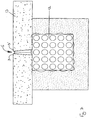
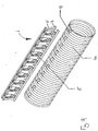
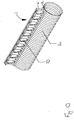
- figs. 8 and 9 illustrate an inlet former 1 in combination with an underlying pipe 14.
- the pipe is provided with cut outs 15 which can be aligned with the location of the conduits in the former defined between the walls 2, 2' and the tubular cross-members 5 to permit the passage of liquid into the slot and down into the pipe via the conduit.
- the pipe 14 may be made from any suitable rigid or strengthened material, but preferably is made from corrugated steel, spirally wound steel, a plastic material or concrete.
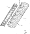
- Figs. 10 and 11 also illustrate an inlet former 1 in combination with an underlying pipe 14.
- the pipe is provided with cut outs 15 which can be aligned with the location of the conduits in the former 1 defined between the walls 2, 2' and tubular cross-members 5 to permit the passage of liquid into the slot and down into the pipe via the conduit.
- the tubular elements 5 are interrupted by a vertical plate 10, creating two opposed, blind lateral openings having face to face contact, one opening to either side of the former.
Landscapes
- Engineering & Computer Science (AREA)
- Health & Medical Sciences (AREA)
- Life Sciences & Earth Sciences (AREA)
- Hydrology & Water Resources (AREA)
- Public Health (AREA)
- Water Supply & Treatment (AREA)
- Architecture (AREA)
- Civil Engineering (AREA)
- Structural Engineering (AREA)
- Pit Excavations, Shoring, Fill Or Stabilisation Of Slopes (AREA)
- Road Paving Structures (AREA)
- Chutes (AREA)
Claims (10)
- Einzelne Einlaufformvorrichtung (1) für ein Oberflächenentwässerungssystem, umfassend einen länglichen Schlitz (6), der bei der Verwendung in einer Fläche liegt, die entwässert werden soll, und einen Kanal, durch den bei der Verwendung Flüssigkeit von der Fläche durch die Einlaufformvorrichtung (1) ablaufen kann, dadurch gekennzeichnet, dass die Formvorrichtung (1) eine oder mehrere Queröffnungen (5) umfasst, in die sich ein Material, in das die Einlaufformvorrichtung (1) bei der Verwendung eingebettet ist, aus einer oder aus beiden Seiten der Einlaufformvorrichtung (1) erstrecken kann, um ein strukturelles Brückenelement zu bilden, wobei die Queröffnung (5) oder mindestens eine der Queröffnungen (5) bei der Verwendung einen kontinuierlichen Durchgang aus einer Seite der Formvorrichtung zur anderen bereitstellt, und wobei die Hauptstruktur der Einlaufformvorrichtung (1) durch zwei Seitenwände, welche mit den Unterkanten geflanscht werden, um nach außen gerichtete Lippen (4, 4') oder eine Reihe von breiten Füßen zu formen, gebildet wird, die dazu benutzt werden können, die Einlaufformvorrichtung (1) an einen darunter liegenden Längskanal (14) anzubringen.
- Einlaufformvorrichtung (1) nach Anspruch 1, wobei die Einlaufformvorrichtung (1) für eine Punktentwässerung konfiguriert ist.
- Einlaufformvorrichtung (1) nach Anspruch 1, wobei die Einlaufformvorrichtung (1) für eine Entwässerungsrinne konfiguriert ist.
- Einlaufformvorrichtung (1) nach einem der Ansprüche 1 bis 3, wobei die Queröffnung (5) oder mindestens eine der Queröffnungen (5) durch eine Wand getrennt ist, die im Wesentlichen in der seitlichen Richtung nicht zusammendrückbar ist.
- Einlaufformvorrichtung (1) nach Anspruch 4, wobei sich die Wand im Wesentlichen in der Mitte der Einlaufformvorrichtung (1) befindet.
- Einlaufformvorrichtung (1) nach einem der vorhergehenden Ansprüche, wobei die Einlaufformvorrichtung (1) unitär ist.
- Einlaufformvorrichtung (1) nach einem der vorhergehenden Ansprüche, wobei die Einlaufformvorrichtung (1) eine oder mehrere seitliche Einlassöffnungen (8) aufweist, wodurch Flüssigkeit in die Einlaufformvorrichtung (1) ablaufen kann.
- Einlaufformvorrichtung nach einem der vorhergehenden Ansprüche, wobei bei der Verwendung ein Filter (6) in der Einlaufformvorrichtung (1) montiert ist.
- Entwässerungssystem mit linearer Oberfläche, umfassend eine einzelne Einlaufformvorrichtung und einen Längskanal (14), wobei die Einlaufformvorrichtung (1) dergestalt konfiguriert ist, dass sie an dem Längskanal (14) angebracht werden kann, so dass bei der Verwendung unter der Einlaufformvorrichtung (1) liegt und in Flüssigkeitsverbindung mit der Einlaufformvorrichtung (1) steht, damit Flüssigkeit durch die Einlaufformvorrichtung in diesen darunter liegenden Kanal (14) ablaufen kann, wobei die Einlaufformvorrichtung (1) einen länglichen Schlitz (6) umfasst, der bei der Verwendung in einer Fläche liegt, die entwässert werden soll und einen Kanal, durch den bei der Verwendung Flüssigkeit von der Fläche durch die Einlaufformvorrichtung (1) ablaufen kann, dadurch gekennzeichnet, dass die Formvorrichtung (1) eine oder mehrere Queröffnungen (5) umfasst, in die sich ein Material, in das die Einlaufformvorrichtung (1) bei der Verwendung eingebettet ist, aus einer oder aus beiden Seiten der Einlaufformvorrichtung (1) erstrecken kann, um ein strukturelles Brückenelement zu bilden, wobei die Queröffnung (5), oder mindestens eine der Queröffnungen (5), bei der Verwendung einen kontinuierlichen Durchgang aus einer Seite der Formvorrichtung zur anderen bereitstellt, und wobei die Hauptstruktur der Einlaufformvorrichtung (1) durch zwei Seitenwände (2, 2'), welche mit den Unterkanten geflanscht werden, um nach außen gerichtete Lippen (4, 4') oder eine Reihe von breiten Füßen zu formen, gebildet wird, die dazu benutzt werden können, die Einlaufformvorrichtung (1) an einen darunter liegenden Längskanal (14) anzubringen.
- Entwässerungssystem mit linearer Oberfläche, umfassend eine Einlaufformvorrichtung nach einem der Ansprüche 2 - 8.
Priority Applications (1)
| Application Number | Priority Date | Filing Date | Title |
|---|---|---|---|
| PL04255634T PL1518964T4 (pl) | 2003-09-23 | 2004-09-16 | System drenażu powierzchniowego |
Applications Claiming Priority (2)
| Application Number | Priority Date | Filing Date | Title |
|---|---|---|---|
| GB0322280A GB2406351B (en) | 2003-09-23 | 2003-09-23 | Surface drainage arrangement |
| GB0322280 | 2003-09-23 |
Publications (3)
| Publication Number | Publication Date |
|---|---|
| EP1518964A1 EP1518964A1 (de) | 2005-03-30 |
| EP1518964B1 EP1518964B1 (de) | 2012-06-27 |
| EP1518964B2 true EP1518964B2 (de) | 2019-01-23 |
Family
ID=29266525
Family Applications (1)
| Application Number | Title | Priority Date | Filing Date |
|---|---|---|---|
| EP04255634.0A Expired - Lifetime EP1518964B2 (de) | 2003-09-23 | 2004-09-16 | Oberflächenentwässerungseinrichtung |
Country Status (6)
| Country | Link |
|---|---|
| EP (1) | EP1518964B2 (de) |
| DK (1) | DK1518964T4 (de) |
| ES (1) | ES2389900T5 (de) |
| GB (1) | GB2406351B (de) |
| PL (1) | PL1518964T4 (de) |
| PT (1) | PT1518964E (de) |
Cited By (1)
| Publication number | Priority date | Publication date | Assignee | Title |
|---|---|---|---|---|
| WO2025078663A1 (de) * | 2023-10-13 | 2025-04-17 | Aco Ahlmann Se & Co. Kg | Entwässerungssystem, verfahren und verwendung |
Families Citing this family (9)
| Publication number | Priority date | Publication date | Assignee | Title |
|---|---|---|---|---|
| JP5153908B2 (ja) * | 2010-04-23 | 2013-02-27 | 株式会社宝機材 | 路面用排水路 |
| EP2520728A1 (de) * | 2011-05-02 | 2012-11-07 | Hauraton GmbH & Co. KG | Einlaufmodul und Verfahren zum Aufbau eines Linieneinlaufs einer Entwässerungsvorrichtung |
| AU2013271362B2 (en) * | 2012-06-06 | 2014-08-28 | Bryan PEACH | Surface drainage system |
| EP2746476A1 (de) * | 2012-12-21 | 2014-06-25 | Hauraton France (Société à Responsabilité Limitée) | Schlitzabdeckvorrichtung für hydraulische Rinne |
| DE102015105084A1 (de) * | 2015-04-01 | 2016-10-06 | ACO Severin Ahlmann GmbH & Co Kommanditgesellschaft | Schlitzrinne |
| GB2577100B (en) * | 2018-09-14 | 2021-03-17 | Tubosider United Kingdom Ltd | Slot drain |
| EP3927889A1 (de) | 2019-02-21 | 2021-12-29 | ACO Severin Ahlmann GmbH & Co. KG | Entwässerungssystem, einheiten und verfahren |
| DE102021102651A1 (de) * | 2021-02-04 | 2022-08-04 | Aco Ahlmann Se & Co. Kg | Oberflächenentwässerungssystem sowie Verfahren zum Herstellen eines solchen |
| US11746517B2 (en) * | 2021-05-05 | 2023-09-05 | Global Drain Technologies Inc. | Coupler for fluidically communicating a hose with a trench drain |
Citations (3)
| Publication number | Priority date | Publication date | Assignee | Title |
|---|---|---|---|---|
| US6000881A (en) † | 1998-02-17 | 1999-12-14 | Zurn Industries, Inc. | Trench drain |
| AU733361B2 (en) † | 1997-08-04 | 2001-05-10 | John Joseph Creighton | Drainage channel and pipe assembly |
| GB2388144A (en) † | 2002-04-29 | 2003-11-05 | Alumasc Ltd | Slot drain for roads, car parks, warehouses etc. |
Family Cites Families (4)
| Publication number | Priority date | Publication date | Assignee | Title |
|---|---|---|---|---|
| GB2311549B (en) | 1996-03-26 | 1999-07-14 | Elkington Gatic Limited | A slot drain |
| DE19910824A1 (de) * | 1999-03-11 | 2000-09-14 | Wilhelm Lueck | Entwässerungsrinne aus Stahlblech |
| US6368017B2 (en) * | 1999-03-16 | 2002-04-09 | Charles E. Black | Storm water detention filter system |
| GB2390630B (en) * | 2002-07-10 | 2004-06-30 | Aco Technologies Plc | Wide channel drainage system |
-
2003
- 2003-09-23 GB GB0322280A patent/GB2406351B/en not_active Expired - Lifetime
-
2004
- 2004-09-16 ES ES04255634T patent/ES2389900T5/es not_active Expired - Lifetime
- 2004-09-16 PL PL04255634T patent/PL1518964T4/pl unknown
- 2004-09-16 DK DK04255634.0T patent/DK1518964T4/en active
- 2004-09-16 PT PT04255634T patent/PT1518964E/pt unknown
- 2004-09-16 EP EP04255634.0A patent/EP1518964B2/de not_active Expired - Lifetime
Patent Citations (3)
| Publication number | Priority date | Publication date | Assignee | Title |
|---|---|---|---|---|
| AU733361B2 (en) † | 1997-08-04 | 2001-05-10 | John Joseph Creighton | Drainage channel and pipe assembly |
| US6000881A (en) † | 1998-02-17 | 1999-12-14 | Zurn Industries, Inc. | Trench drain |
| GB2388144A (en) † | 2002-04-29 | 2003-11-05 | Alumasc Ltd | Slot drain for roads, car parks, warehouses etc. |
Cited By (1)
| Publication number | Priority date | Publication date | Assignee | Title |
|---|---|---|---|---|
| WO2025078663A1 (de) * | 2023-10-13 | 2025-04-17 | Aco Ahlmann Se & Co. Kg | Entwässerungssystem, verfahren und verwendung |
Also Published As
| Publication number | Publication date |
|---|---|
| EP1518964B1 (de) | 2012-06-27 |
| GB0322280D0 (en) | 2003-10-22 |
| ES2389900T3 (es) | 2012-11-02 |
| PL1518964T5 (pl) | 2019-05-31 |
| PL1518964T3 (pl) | 2012-12-31 |
| PL1518964T4 (pl) | 2021-09-20 |
| GB2406351B (en) | 2008-04-02 |
| PT1518964E (pt) | 2012-09-25 |
| GB2406351A (en) | 2005-03-30 |
| ES2389900T5 (es) | 2019-07-10 |
| DK1518964T4 (en) | 2019-04-23 |
| DK1518964T3 (da) | 2012-09-17 |
| EP1518964A1 (de) | 2005-03-30 |
Similar Documents
| Publication | Publication Date | Title |
|---|---|---|
| US8113740B2 (en) | Method and apparatus for capturing, storing, and distributing storm water | |
| KR101509202B1 (ko) | 친환경 수로형 집수정 및 그것을 이용한 배수 시스템을 구비하는 친환경 도로 구조물 | |
| JP4284665B2 (ja) | 側溝の排水構造 | |
| US20120201603A1 (en) | Method and Apparatus for Capturing, Storing, and Distributing Storm Water | |
| EP2811075A1 (de) | Tunnelanordnung | |
| EP1518964B2 (de) | Oberflächenentwässerungseinrichtung | |
| JP4268922B2 (ja) | 排水システムにおける浸透管付き取水桝及び排水システム | |
| EP1380691B1 (de) | Breite Entwässerungsrinne | |
| JP5083602B2 (ja) | 流出抑制街渠工 | |
| JP3232449U (ja) | 暗渠型側溝 | |
| EP1520942B1 (de) | Oberflächenentwässerung | |
| KR200224492Y1 (ko) | 측구용 투수 콘크리트블록 | |
| JP2005179919A (ja) | 雨水等の貯留浸透施設 | |
| JP2000179034A (ja) | 側溝、側溝の蓋部材、および境界ブロック | |
| JP3605537B2 (ja) | 排水性舗装路面の排水構造 | |
| JP4583215B2 (ja) | 雨水流出抑制排水路構造 | |
| JP2011047107A (ja) | 歩車道境界ブロック及び歩車道境界排水構造 | |
| JP4237071B2 (ja) | 道路構造物の排水装置及び排水方法 | |
| JP2007239424A (ja) | 越流浸透兼用排水ブロック工 | |
| KR102940813B1 (ko) | 도로 선배수로의 측구 시공시스템 | |
| EP4692481A1 (de) | Modularer regenwasserrückhaltetank | |
| EP1520943A2 (de) | Oberflächenentwässerungssystem | |
| JP2559319Y2 (ja) | 道路側溝ブロック体 | |
| JP3154026U (ja) | 越流浸透兼用排水ブロック工 | |
| AU626564B2 (en) | A method and apparatus for forming a drain |
Legal Events
| Date | Code | Title | Description |
|---|---|---|---|
| PUAI | Public reference made under article 153(3) epc to a published international application that has entered the european phase |
Free format text: ORIGINAL CODE: 0009012 |
|
| AK | Designated contracting states |
Kind code of ref document: A1 Designated state(s): AT BE BG CH CY CZ DE DK EE ES FI FR GB GR HU IE IT LI LU MC NL PL PT RO SE SI SK TR |
|
| AX | Request for extension of the european patent |
Extension state: AL HR LT LV MK |
|
| RIN1 | Information on inventor provided before grant (corrected) |
Inventor name: KING, ROBERT JAMES |
|
| 17P | Request for examination filed |
Effective date: 20050922 |
|
| R17P | Request for examination filed (corrected) |
Effective date: 20050922 |
|
| AKX | Designation fees paid |
Designated state(s): AT BE BG CH CY CZ DE DK EE ES FI FR GB GR HU IE IT LI LU MC NL PL PT RO SE SI SK TR |
|
| 17Q | First examination report despatched |
Effective date: 20080903 |
|
| GRAP | Despatch of communication of intention to grant a patent |
Free format text: ORIGINAL CODE: EPIDOSNIGR1 |
|
| GRAC | Information related to communication of intention to grant a patent modified |
Free format text: ORIGINAL CODE: EPIDOSCIGR1 |
|
| GRAS | Grant fee paid |
Free format text: ORIGINAL CODE: EPIDOSNIGR3 |
|
| GRAA | (expected) grant |
Free format text: ORIGINAL CODE: 0009210 |
|
| AK | Designated contracting states |
Kind code of ref document: B1 Designated state(s): AT BE BG CH CY CZ DE DK EE ES FI FR GB GR HU IE IT LI LU MC NL PL PT RO SE SI SK TR |
|
| REG | Reference to a national code |
Ref country code: GB Ref legal event code: FG4D |
|
| REG | Reference to a national code |
Ref country code: CH Ref legal event code: EP |
|
| REG | Reference to a national code |
Ref country code: AT Ref legal event code: REF Ref document number: 564328 Country of ref document: AT Kind code of ref document: T Effective date: 20120715 |
|
| REG | Reference to a national code |
Ref country code: IE Ref legal event code: FG4D |
|
| REG | Reference to a national code |
Ref country code: DE Ref legal event code: R096 Ref document number: 602004038355 Country of ref document: DE Effective date: 20120816 |
|
| REG | Reference to a national code |
Ref country code: DK Ref legal event code: T3 |
|
| REG | Reference to a national code |
Ref country code: RO Ref legal event code: EPE |
|
| REG | Reference to a national code |
Ref country code: PT Ref legal event code: SC4A Free format text: AVAILABILITY OF NATIONAL TRANSLATION Effective date: 20120918 |
|
| REG | Reference to a national code |
Ref country code: SE Ref legal event code: TRGR |
|
| REG | Reference to a national code |
Ref country code: ES Ref legal event code: FG2A Ref document number: 2389900 Country of ref document: ES Kind code of ref document: T3 Effective date: 20121102 |
|
| REG | Reference to a national code |
Ref country code: NL Ref legal event code: VDEP Effective date: 20120627 |
|
| PG25 | Lapsed in a contracting state [announced via postgrant information from national office to epo] |
Ref country code: GR Free format text: LAPSE BECAUSE OF FAILURE TO SUBMIT A TRANSLATION OF THE DESCRIPTION OR TO PAY THE FEE WITHIN THE PRESCRIBED TIME-LIMIT Effective date: 20120928 Ref country code: SI Free format text: LAPSE BECAUSE OF FAILURE TO SUBMIT A TRANSLATION OF THE DESCRIPTION OR TO PAY THE FEE WITHIN THE PRESCRIBED TIME-LIMIT Effective date: 20120627 |
|
| REG | Reference to a national code |
Ref country code: PL Ref legal event code: T3 |
|
| PG25 | Lapsed in a contracting state [announced via postgrant information from national office to epo] |
Ref country code: BE Free format text: LAPSE BECAUSE OF FAILURE TO SUBMIT A TRANSLATION OF THE DESCRIPTION OR TO PAY THE FEE WITHIN THE PRESCRIBED TIME-LIMIT Effective date: 20120627 Ref country code: CY Free format text: LAPSE BECAUSE OF FAILURE TO SUBMIT A TRANSLATION OF THE DESCRIPTION OR TO PAY THE FEE WITHIN THE PRESCRIBED TIME-LIMIT Effective date: 20120627 |
|
| REG | Reference to a national code |
Ref country code: SK Ref legal event code: T3 Ref document number: E 12841 Country of ref document: SK |
|
| REG | Reference to a national code |
Ref country code: EE Ref legal event code: FG4A Ref document number: E007460 Country of ref document: EE Effective date: 20120924 |
|
| PG25 | Lapsed in a contracting state [announced via postgrant information from national office to epo] |
Ref country code: NL Free format text: LAPSE BECAUSE OF FAILURE TO SUBMIT A TRANSLATION OF THE DESCRIPTION OR TO PAY THE FEE WITHIN THE PRESCRIBED TIME-LIMIT Effective date: 20120627 |
|
| PLBI | Opposition filed |
Free format text: ORIGINAL CODE: 0009260 |
|
| REG | Reference to a national code |
Ref country code: DE Ref legal event code: R119 Ref document number: 602004038355 Country of ref document: DE |
|
| PG25 | Lapsed in a contracting state [announced via postgrant information from national office to epo] |
Ref country code: MC Free format text: LAPSE BECAUSE OF NON-PAYMENT OF DUE FEES Effective date: 20120930 |
|
| REG | Reference to a national code |
Ref country code: CH Ref legal event code: PL |
|
| 26 | Opposition filed |
Opponent name: HAURATON GMBH & CO. KG Effective date: 20130327 |
|
| PLAX | Notice of opposition and request to file observation + time limit sent |
Free format text: ORIGINAL CODE: EPIDOSNOBS2 |
|
| REG | Reference to a national code |
Ref country code: IE Ref legal event code: MM4A |
|
| REG | Reference to a national code |
Ref country code: DE Ref legal event code: R026 Ref document number: 602004038355 Country of ref document: DE Effective date: 20130327 |
|
| PG25 | Lapsed in a contracting state [announced via postgrant information from national office to epo] |
Ref country code: BG Free format text: LAPSE BECAUSE OF FAILURE TO SUBMIT A TRANSLATION OF THE DESCRIPTION OR TO PAY THE FEE WITHIN THE PRESCRIBED TIME-LIMIT Effective date: 20120927 Ref country code: CH Free format text: LAPSE BECAUSE OF NON-PAYMENT OF DUE FEES Effective date: 20120930 Ref country code: LI Free format text: LAPSE BECAUSE OF NON-PAYMENT OF DUE FEES Effective date: 20120930 Ref country code: DE Free format text: LAPSE BECAUSE OF NON-PAYMENT OF DUE FEES Effective date: 20130403 Ref country code: IE Free format text: LAPSE BECAUSE OF NON-PAYMENT OF DUE FEES Effective date: 20120916 |
|
| REG | Reference to a national code |
Ref country code: HU Ref legal event code: AG4A Ref document number: E016204 Country of ref document: HU |
|
| PLBB | Reply of patent proprietor to notice(s) of opposition received |
Free format text: ORIGINAL CODE: EPIDOSNOBS3 |
|
| REG | Reference to a national code |
Ref country code: DE Ref legal event code: R119 Ref document number: 602004038355 Country of ref document: DE Effective date: 20130403 |
|
| REG | Reference to a national code |
Ref country code: DE Ref legal event code: R073 Ref document number: 602004038355 Country of ref document: DE |
|
| REG | Reference to a national code |
Ref country code: DE Ref legal event code: R074 Ref document number: 602004038355 Country of ref document: DE |
|
| REG | Reference to a national code |
Ref country code: DE Ref legal event code: R074 Ref document number: 602004038355 Country of ref document: DE Effective date: 20140114 Ref country code: DE Ref legal event code: R074 Ref document number: 602004038355 Country of ref document: DE Effective date: 20140117 |
|
| PG25 | Lapsed in a contracting state [announced via postgrant information from national office to epo] |
Ref country code: TR Free format text: LAPSE BECAUSE OF FAILURE TO SUBMIT A TRANSLATION OF THE DESCRIPTION OR TO PAY THE FEE WITHIN THE PRESCRIBED TIME-LIMIT Effective date: 20120627 |
|
| PGRI | Patent reinstated in contracting state [announced from national office to epo] |
Ref country code: DE Effective date: 20140114 |
|
| PG25 | Lapsed in a contracting state [announced via postgrant information from national office to epo] |
Ref country code: LU Free format text: LAPSE BECAUSE OF NON-PAYMENT OF DUE FEES Effective date: 20120916 |
|
| PLAY | Examination report in opposition despatched + time limit |
Free format text: ORIGINAL CODE: EPIDOSNORE2 |
|
| PLBC | Reply to examination report in opposition received |
Free format text: ORIGINAL CODE: EPIDOSNORE3 |
|
| REG | Reference to a national code |
Ref country code: FR Ref legal event code: PLFP Year of fee payment: 13 |
|
| APBM | Appeal reference recorded |
Free format text: ORIGINAL CODE: EPIDOSNREFNO |
|
| APBP | Date of receipt of notice of appeal recorded |
Free format text: ORIGINAL CODE: EPIDOSNNOA2O |
|
| RDAF | Communication despatched that patent is revoked |
Free format text: ORIGINAL CODE: EPIDOSNREV1 |
|
| STAA | Information on the status of an ep patent application or granted ep patent |
Free format text: STATUS: THE PATENT HAS BEEN GRANTED |
|
| APAH | Appeal reference modified |
Free format text: ORIGINAL CODE: EPIDOSCREFNO |
|
| APAJ | Date of receipt of notice of appeal modified |
Free format text: ORIGINAL CODE: EPIDOSCNOA2O |
|
| APBQ | Date of receipt of statement of grounds of appeal recorded |
Free format text: ORIGINAL CODE: EPIDOSNNOA3O |
|
| REG | Reference to a national code |
Ref country code: FR Ref legal event code: PLFP Year of fee payment: 14 |
|
| APBU | Appeal procedure closed |
Free format text: ORIGINAL CODE: EPIDOSNNOA9O |
|
| REG | Reference to a national code |
Ref country code: FR Ref legal event code: PLFP Year of fee payment: 15 |
|
| PUAH | Patent maintained in amended form |
Free format text: ORIGINAL CODE: 0009272 |
|
| STAA | Information on the status of an ep patent application or granted ep patent |
Free format text: STATUS: PATENT MAINTAINED AS AMENDED |
|
| 27A | Patent maintained in amended form |
Effective date: 20190123 |
|
| AK | Designated contracting states |
Kind code of ref document: B2 Designated state(s): AT BE BG CH CY CZ DE DK EE ES FI FR GB GR HU IE IT LI LU MC NL PL PT RO SE SI SK TR |
|
| REG | Reference to a national code |
Ref country code: DE Ref legal event code: R102 Ref document number: 602004038355 Country of ref document: DE |
|
| REG | Reference to a national code |
Ref country code: DE Ref legal event code: R082 Ref document number: 602004038355 Country of ref document: DE Representative=s name: VIERING, JENTSCHURA & PARTNER MBB PATENT- UND , DE Ref country code: DE Ref legal event code: R082 Ref document number: 602004038355 Country of ref document: DE Representative=s name: D YOUNG & CO LLP, DE |
|
| REG | Reference to a national code |
Ref country code: DE Ref legal event code: R008 Ref document number: 602004038355 Country of ref document: DE Ref country code: DE Ref legal event code: R039 Ref document number: 602004038355 Country of ref document: DE |
|
| REG | Reference to a national code |
Ref country code: SE Ref legal event code: RPEO |
|
| REG | Reference to a national code |
Ref country code: DK Ref legal event code: T4 Effective date: 20190415 |
|
| REG | Reference to a national code |
Ref country code: SK Ref legal event code: T5 Ref document number: E 12841 Country of ref document: SK |
|
| REG | Reference to a national code |
Ref country code: EE Ref legal event code: LD4A Ref document number: E007460 Country of ref document: EE |
|
| REG | Reference to a national code |
Ref country code: ES Ref legal event code: DC2A Ref document number: 2389900 Country of ref document: ES Kind code of ref document: T5 Effective date: 20190710 |
|
| REG | Reference to a national code |
Ref country code: DE Ref legal event code: R082 Ref document number: 602004038355 Country of ref document: DE Representative=s name: VIERING, JENTSCHURA & PARTNER MBB PATENT- UND , DE |
|
| REG | Reference to a national code |
Ref country code: DE Ref legal event code: R040 Ref document number: 602004038355 Country of ref document: DE |
|
| REG | Reference to a national code |
Ref country code: EE Ref legal event code: HC1A Ref document number: E007460 Country of ref document: EE |
|
| REG | Reference to a national code |
Ref country code: AT Ref legal event code: UEP Ref document number: 564328 Country of ref document: AT Kind code of ref document: T Effective date: 20190123 |
|
| PGFP | Annual fee paid to national office [announced via postgrant information from national office to epo] |
Ref country code: RO Payment date: 20230907 Year of fee payment: 20 Ref country code: GB Payment date: 20230921 Year of fee payment: 20 Ref country code: FI Payment date: 20230918 Year of fee payment: 20 Ref country code: EE Payment date: 20230915 Year of fee payment: 20 Ref country code: CZ Payment date: 20230901 Year of fee payment: 20 Ref country code: AT Payment date: 20230915 Year of fee payment: 20 |
|
| PGFP | Annual fee paid to national office [announced via postgrant information from national office to epo] |
Ref country code: SK Payment date: 20230907 Year of fee payment: 20 Ref country code: SE Payment date: 20230921 Year of fee payment: 20 Ref country code: PT Payment date: 20230912 Year of fee payment: 20 Ref country code: PL Payment date: 20230906 Year of fee payment: 20 Ref country code: HU Payment date: 20230911 Year of fee payment: 20 Ref country code: FR Payment date: 20230918 Year of fee payment: 20 Ref country code: DK Payment date: 20230921 Year of fee payment: 20 Ref country code: DE Payment date: 20230919 Year of fee payment: 20 |
|
| PGFP | Annual fee paid to national office [announced via postgrant information from national office to epo] |
Ref country code: ES Payment date: 20231019 Year of fee payment: 20 |
|
| PGFP | Annual fee paid to national office [announced via postgrant information from national office to epo] |
Ref country code: IT Payment date: 20230929 Year of fee payment: 20 |
|
| REG | Reference to a national code |
Ref country code: DE Ref legal event code: R071 Ref document number: 602004038355 Country of ref document: DE |
|
| REG | Reference to a national code |
Ref country code: DK Ref legal event code: EUP Expiry date: 20240916 |
|
| REG | Reference to a national code |
Ref country code: ES Ref legal event code: FD2A Effective date: 20240927 |
|
| REG | Reference to a national code |
Ref country code: GB Ref legal event code: PE20 Expiry date: 20240915 Ref country code: SK Ref legal event code: MK4A Ref document number: E 12841 Country of ref document: SK Expiry date: 20240916 |
|
| PG25 | Lapsed in a contracting state [announced via postgrant information from national office to epo] |
Ref country code: PT Free format text: LAPSE BECAUSE OF EXPIRATION OF PROTECTION Effective date: 20240925 Ref country code: GB Free format text: LAPSE BECAUSE OF EXPIRATION OF PROTECTION Effective date: 20240915 |
|
| PG25 | Lapsed in a contracting state [announced via postgrant information from national office to epo] |
Ref country code: ES Free format text: LAPSE BECAUSE OF EXPIRATION OF PROTECTION Effective date: 20240917 |
|
| PG25 | Lapsed in a contracting state [announced via postgrant information from national office to epo] |
Ref country code: CZ Free format text: LAPSE BECAUSE OF EXPIRATION OF PROTECTION Effective date: 20240916 |
|
| PG25 | Lapsed in a contracting state [announced via postgrant information from national office to epo] |
Ref country code: SK Free format text: LAPSE BECAUSE OF EXPIRATION OF PROTECTION Effective date: 20240916 |
|
| REG | Reference to a national code |
Ref country code: SE Ref legal event code: EUG |
|
| PG25 | Lapsed in a contracting state [announced via postgrant information from national office to epo] |
Ref country code: SK Free format text: LAPSE BECAUSE OF EXPIRATION OF PROTECTION Effective date: 20240916 Ref country code: PT Free format text: LAPSE BECAUSE OF EXPIRATION OF PROTECTION Effective date: 20240925 Ref country code: GB Free format text: LAPSE BECAUSE OF EXPIRATION OF PROTECTION Effective date: 20240915 Ref country code: ES Free format text: LAPSE BECAUSE OF EXPIRATION OF PROTECTION Effective date: 20240917 Ref country code: CZ Free format text: LAPSE BECAUSE OF EXPIRATION OF PROTECTION Effective date: 20240916 |
|
| REG | Reference to a national code |
Ref country code: AT Ref legal event code: MK07 Ref document number: 564328 Country of ref document: AT Kind code of ref document: T Effective date: 20240916 |