EP1519145A1 - Ensemble capteur - Google Patents
Ensemble capteur Download PDFInfo
- Publication number
- EP1519145A1 EP1519145A1 EP04104009A EP04104009A EP1519145A1 EP 1519145 A1 EP1519145 A1 EP 1519145A1 EP 04104009 A EP04104009 A EP 04104009A EP 04104009 A EP04104009 A EP 04104009A EP 1519145 A1 EP1519145 A1 EP 1519145A1
- Authority
- EP
- European Patent Office
- Prior art keywords
- sensor
- arrangement
- conductor carrier
- contact
- wedge
- Prior art date
- Legal status (The legal status is an assumption and is not a legal conclusion. Google has not performed a legal analysis and makes no representation as to the accuracy of the status listed.)
- Granted
Links
Images

Classifications
-
- G—PHYSICS
- G01—MEASURING; TESTING
- G01C—MEASURING DISTANCES, LEVELS OR BEARINGS; SURVEYING; NAVIGATION; GYROSCOPIC INSTRUMENTS; PHOTOGRAMMETRY OR VIDEOGRAMMETRY
- G01C19/00—Gyroscopes; Turn-sensitive devices using vibrating masses; Turn-sensitive devices without moving masses; Measuring angular rate using gyroscopic effects
- G01C19/56—Turn-sensitive devices using vibrating masses, e.g. vibratory angular rate sensors based on Coriolis forces
-
- G—PHYSICS
- G01—MEASURING; TESTING
- G01C—MEASURING DISTANCES, LEVELS OR BEARINGS; SURVEYING; NAVIGATION; GYROSCOPIC INSTRUMENTS; PHOTOGRAMMETRY OR VIDEOGRAMMETRY
- G01C25/00—Manufacturing, calibrating, cleaning, or repairing instruments or devices referred to in the other groups of this subclass
- G01C25/005—Manufacturing, calibrating, cleaning, or repairing instruments or devices referred to in the other groups of this subclass initial alignment, calibration or starting-up of inertial devices
-
- G—PHYSICS
- G01—MEASURING; TESTING
- G01C—MEASURING DISTANCES, LEVELS OR BEARINGS; SURVEYING; NAVIGATION; GYROSCOPIC INSTRUMENTS; PHOTOGRAMMETRY OR VIDEOGRAMMETRY
- G01C9/00—Measuring inclination, e.g. by clinometers, by levels
- G01C9/18—Measuring inclination, e.g. by clinometers, by levels by using liquids
- G01C9/24—Measuring inclination, e.g. by clinometers, by levels by using liquids in closed containers partially filled with liquid so as to leave a gas bubble
- G01C9/26—Details
- G01C9/28—Mountings
-
- G—PHYSICS
- G01—MEASURING; TESTING
- G01D—MEASURING NOT SPECIALLY ADAPTED FOR A SPECIFIC VARIABLE; ARRANGEMENTS FOR MEASURING TWO OR MORE VARIABLES NOT COVERED IN A SINGLE OTHER SUBCLASS; TARIFF METERING APPARATUS; MEASURING OR TESTING NOT OTHERWISE PROVIDED FOR
- G01D11/00—Component parts of measuring arrangements not specially adapted for a specific variable
- G01D11/30—Supports specially adapted for an instrument; Supports specially adapted for a set of instruments
-
- G—PHYSICS
- G01—MEASURING; TESTING
- G01P—MEASURING LINEAR OR ANGULAR SPEED, ACCELERATION, DECELERATION, OR SHOCK; INDICATING PRESENCE, ABSENCE, OR DIRECTION, OF MOVEMENT
- G01P1/00—Details of instruments
-
- G—PHYSICS
- G01—MEASURING; TESTING
- G01P—MEASURING LINEAR OR ANGULAR SPEED, ACCELERATION, DECELERATION, OR SHOCK; INDICATING PRESENCE, ABSENCE, OR DIRECTION, OF MOVEMENT
- G01P1/00—Details of instruments
- G01P1/02—Housings
- G01P1/023—Housings for acceleration measuring devices
Definitions
- the invention relates to an arrangement with a sensor for Measurement of a position, in particular an angular position, movement or acceleration, with a conductor carrier on which the sensor is attached and with electrical connections, by means of which the sensor on lines of the conductor carrier electrically contacted, wherein the conductor carrier obliquely in Space is aligned.
- the above arrangement is regularly used.
- One of the most common applications is in the Automotive technology, where regular sensors for the determination the angular position, the acceleration or the state of motion be mounted on ladder carriers or printed circuit boards. The space conditions sometimes cause an oblique here Arrangement of the conductor carrier or the printed circuit board.
- sensors require a flawless Function a vertical installation position or have a Reference axis on, which at zero point conditions of the measurement should be parallel to the gravitational acceleration. Therefore it is necessary to use the sensors for correct alignment of the Reference axis to be arranged obliquely to the conductor carrier and on to attach this.
- the invention has for its object to provide an arrangement, the most cost-effective the connection of a position, motion or acceleration sensor on a crooked in space arranged conductor carrier allows.
- the object by means of an arrangement of solved in the beginning type, in which between the sensor and the Ladder carrier a wedge-shaped fitting is arranged, which two opposite and one wedge angle with each other having enclosing, substantially planar contact surfaces, wherein a first contact surface bears against the conductor carrier and a second contact surface on a contact area of the sensor is applied, wherein the wedge angle is selected so that a reference axis the sensor is essentially in the direction of acceleration of gravity extends.
- the oblique orientation in the room means Here, that the conductor carrier an angle with the Includes horizontal, which is nonzero.
- the essence the flatness of the contact surfaces lies in the fact that the contact surfaces although projections for centering or fastening, in particular for locking the fitting to adjacent components may have, but at least one flat surface is provided, which on an adjacent component, in particular the sensor or the conductor carrier, is applied.
- the reference axis of the sensor can be an axis, which at zero measurement of the sensor preferably in the direction of gravitational acceleration points, thus optimal measuring results in the entire measuring range can be achieved.
- a decisive advantage of the arrangement according to the invention is because the additional PCB for the sensor, saved as usual in the prior art and at the same time an attachment for the sensor on the conductor carrier is provided.
- the sensor forms with the conductor carrier according to the invention, a compact Module, what the assembly and mounting in the motor vehicle simplified.
- a typical application of the invention is in the attachment of a sensor for angle measurement, which often referred to as a gyrometer and regularly a horizontal installation position with regard to its contact surface, protruding from the contact pins required.
- An expedient development of the invention provides that the fitting at least one resilient latching hook on the having first contact surface, and the conductor carrier with a the latch hook corresponding recess, through which the catch hook is at least partially passable and to which the latching hook can be latched.
- An even better one Stability of the connection of the fitting with the conductor carrier arises when at the fitting at least two with the conductor carrier latching latching hooks are provided.
- a resilient latching connection the fitting for attachment to the sensor This can be, for example by means of at least one barb-shaped projection on the sensor and at least one with the projection realized corresponding resilient recess on the fitting become.
- the invention provides that the corresponding contacts in the recesses preferably by means of an electrically conductive Metal sleeve extended in the direction of the conductor carrier be and in this way by means of the metal sleeve an electric conductive connection between the contacts of the sensor and the lines of the conductor carrier is made. Cost effective, the regularly as cylindrical pins trained contacts if necessary by means of a commercial Cable end sleeve for extension in the direction of the conductor carrier be provided.
- the contacts of the sensor means a soldering to be connected to a metal sleeve extending, and of particular advantage here is the contacts, the metal sleeve and corresponding lines on the conductor carrier to solder together in one step.
- a weld in the connection of the metal sleeve with the Preferable contacts of the sensor wherein a laser welding is particularly appropriate.
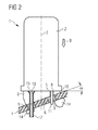
- the arrangement 1 consists essentially of a sensor 2, a Shaped piece 3 and a conductor carrier 4, wherein the shaped piece. 3 is located between the sensor 2 and the conductor carrier 4.
- the molding 3 is wedge-shaped, wherein a first Contact surface 5 a wedge angle ⁇ with a second contact surface 6 includes.
- the conductor carrier 4 is inclined in space arranged and closes with the horizontal also the Wedge angle ⁇ a, so that it makes an angle to the vertical of 90 ° - ⁇ forms.
- the angle measuring sensor 2 has a reference axis 7, which according to a technical specification of the sensor 2 at zero-point measurement conditions in Direction of gravitational g should point g so optimal Measurement results can be achieved over the entire measuring range can. Facing the conductor carrier 4, the sensor 2 a plant area 8, which in the assembled state the arrangement 1 at the first contact surface 5 of the molding 3 is present. The second contact surface 6 of the molded piece 3 is located directly on the conductor carrier 4. The sensor 2 is available not shown lines of the conductor carrier 4 by means Contacts 10, 11 in electrically conductive connection 9.
- the sensor is by means of a latching connection 13 on the fitting 3 attached, and the fitting 3 is by means of locking hooks 14 attached to the conductor carrier 4.
- the fitting 3 instructs the positions that the contacts 10, 11 of the sensor 2 at Facing each other, recesses 15, 16 on, in which the contacts 10, 11 are insertable during assembly and extending from the first contact surface 5 through extend to the second contact surface 6. Due to the wedge shape of the molding 3, the recesses 15, 16 of different long longitudinal extent, so that the contacts 10, 11 commercially available sensors 2 at a corresponding wedge angle ⁇ for an electrical contact on lines of the conductor carrier 4 are not long enough.
- a electrically conductive metal sleeve 17 attached to the contacts 10, which the contacts 10 in the direction of the conductor carrier 4 extended for the purpose of electrical contact.
Landscapes
- Physics & Mathematics (AREA)
- General Physics & Mathematics (AREA)
- Engineering & Computer Science (AREA)
- Radar, Positioning & Navigation (AREA)
- Remote Sensing (AREA)
- Manufacturing & Machinery (AREA)
- Measurement Of Length, Angles, Or The Like Using Electric Or Magnetic Means (AREA)
- Force Measurement Appropriate To Specific Purposes (AREA)
- Air Bags (AREA)
- Ultra Sonic Daignosis Equipment (AREA)
- Pinball Game Machines (AREA)
- Investigating Or Analyzing Materials By The Use Of Electric Means (AREA)
- Handcart (AREA)
- Measuring Fluid Pressure (AREA)
- Gyroscopes (AREA)
Applications Claiming Priority (2)
| Application Number | Priority Date | Filing Date | Title |
|---|---|---|---|
| DE10345632A DE10345632B4 (de) | 2003-09-29 | 2003-09-29 | Anordnung mit einem Sensor |
| DE10345632 | 2003-09-29 |
Publications (2)
| Publication Number | Publication Date |
|---|---|
| EP1519145A1 true EP1519145A1 (fr) | 2005-03-30 |
| EP1519145B1 EP1519145B1 (fr) | 2007-10-10 |
Family
ID=34178033
Family Applications (1)
| Application Number | Title | Priority Date | Filing Date |
|---|---|---|---|
| EP04104009A Expired - Lifetime EP1519145B1 (fr) | 2003-09-29 | 2004-08-20 | Ensemble capteur |
Country Status (3)
| Country | Link |
|---|---|
| EP (1) | EP1519145B1 (fr) |
| AT (1) | ATE375496T1 (fr) |
| DE (2) | DE10345632B4 (fr) |
Cited By (2)
| Publication number | Priority date | Publication date | Assignee | Title |
|---|---|---|---|---|
| EP1672319A1 (fr) * | 2004-12-17 | 2006-06-21 | Siemens Aktiengesellschaft | Ordinateur de navigation muni d'un gyrocapteur |
| WO2007046045A3 (fr) * | 2005-10-21 | 2007-07-12 | Koninkl Philips Electronics Nv | Composant conçu pour etre monte sur un substrat et procede de montage d'un dispositif monte en surface |
Families Citing this family (2)
| Publication number | Priority date | Publication date | Assignee | Title |
|---|---|---|---|---|
| DE102007053808B4 (de) | 2007-11-12 | 2023-07-06 | Robert Bosch Gmbh | Sockelelement, Sockelanordnung und Verfahren zur Herstellung einer weiteren Sockelanordnung |
| DE102021117700A1 (de) | 2021-07-08 | 2023-01-12 | Pierburg Gmbh | Sensorbefestigungsanordnung |
Citations (3)
| Publication number | Priority date | Publication date | Assignee | Title |
|---|---|---|---|---|
| DE19720106A1 (de) * | 1997-05-16 | 1998-11-19 | Telefunken Microelectron | Vorrichtung zur Aufnahme von elektrischen Bauteilen |
| US6215672B1 (en) * | 1997-04-01 | 2001-04-10 | Kelsey-Hayes Company | Mounting structure for an acceleration sensor |
| WO2003008244A1 (fr) * | 2001-07-19 | 2003-01-30 | Kelsey-Hayes Company | Capteurs de mouvement integres dans une unite de commande hydroelectrique |
Family Cites Families (3)
| Publication number | Priority date | Publication date | Assignee | Title |
|---|---|---|---|---|
| DE19637079C2 (de) * | 1996-09-12 | 2000-05-25 | Telefunken Microelectron | Anordnung zur Beschleunigungsmessung |
| DE10209615A1 (de) * | 2002-03-05 | 2003-09-18 | Bosch Gmbh Robert | Vorrichtung und Verfahren zur Fixierung eines Sensormittels |
| DE20304602U1 (de) * | 2003-03-19 | 2003-06-05 | Valeo Schalter und Sensoren GmbH, 74321 Bietigheim-Bissingen | Halter für einen Sensor |
-
2003
- 2003-09-29 DE DE10345632A patent/DE10345632B4/de not_active Expired - Fee Related
-
2004
- 2004-08-20 EP EP04104009A patent/EP1519145B1/fr not_active Expired - Lifetime
- 2004-08-20 DE DE502004005187T patent/DE502004005187D1/de not_active Expired - Lifetime
- 2004-08-20 AT AT04104009T patent/ATE375496T1/de active
Patent Citations (3)
| Publication number | Priority date | Publication date | Assignee | Title |
|---|---|---|---|---|
| US6215672B1 (en) * | 1997-04-01 | 2001-04-10 | Kelsey-Hayes Company | Mounting structure for an acceleration sensor |
| DE19720106A1 (de) * | 1997-05-16 | 1998-11-19 | Telefunken Microelectron | Vorrichtung zur Aufnahme von elektrischen Bauteilen |
| WO2003008244A1 (fr) * | 2001-07-19 | 2003-01-30 | Kelsey-Hayes Company | Capteurs de mouvement integres dans une unite de commande hydroelectrique |
Cited By (4)
| Publication number | Priority date | Publication date | Assignee | Title |
|---|---|---|---|---|
| EP1672319A1 (fr) * | 2004-12-17 | 2006-06-21 | Siemens Aktiengesellschaft | Ordinateur de navigation muni d'un gyrocapteur |
| WO2007046045A3 (fr) * | 2005-10-21 | 2007-07-12 | Koninkl Philips Electronics Nv | Composant conçu pour etre monte sur un substrat et procede de montage d'un dispositif monte en surface |
| US8045334B2 (en) | 2005-10-21 | 2011-10-25 | Koninklijke Philips Electronics N.V. | Component adapted for being mounted on a substrate and a method of mounting a surface mounted device |
| CN101292576B (zh) * | 2005-10-21 | 2012-05-02 | 皇家飞利浦电子股份有限公司 | 适合于安装在基板上的器件和安装表面安装设备的方法 |
Also Published As
| Publication number | Publication date |
|---|---|
| ATE375496T1 (de) | 2007-10-15 |
| DE502004005187D1 (de) | 2007-11-22 |
| DE10345632A1 (de) | 2005-05-12 |
| DE10345632B4 (de) | 2006-01-05 |
| EP1519145B1 (fr) | 2007-10-10 |
Similar Documents
| Publication | Publication Date | Title |
|---|---|---|
| EP1950836B1 (fr) | Borne de connexion électrique | |
| EP0924971B1 (fr) | Dispositif pour la connexion de plaques à circuit imprimé | |
| EP1890162B1 (fr) | Dispositif de mesure électrique | |
| DE102011087328B4 (de) | Verfahren zur Herstellung einer umspritzten Sensorbaugruppe sowie eine Sensorbaugruppe | |
| EP3552463B1 (fr) | Assemblage de cartes de circuits imprimés et son procédé de fabrication | |
| EP2762839B1 (fr) | Dispositif d'adaptateur doté d'une interface mécanique pour un boîtier d'appareil de mesure | |
| DE20012623U1 (de) | Gehäuse für ein elektronisches Steuergerät in Fahrzeugen | |
| DE102009060521A1 (de) | Vorrichtung zur kontaktierenden Aufnahme einer Kabelader | |
| DE69304640T2 (de) | Oberflächen montierter elektrische Verbinder für Leiterplatten | |
| DE10355456A1 (de) | Vorrichtung und Verfahren zum Kontaktieren einer Leiterplatte mittels eines Steckverbinders | |
| DE102010017361A1 (de) | Anbausteckverbinder | |
| EP2036414A1 (fr) | Dispositif de fixation et procédé de fixation d'un circuit imprimé dans in boîtier | |
| EP2085785B1 (fr) | Dispositif destiné à la mesure du courant | |
| DE112019002694B4 (de) | Verbinder | |
| DE102005059990B4 (de) | Steckverbinder zur Verbindung elektronischer Bauelemente | |
| DE10107630B4 (de) | Stiftleiste und Sensorsystem für Kraftfahrzeuge mit derartiger Stiftleiste | |
| DE10345632B4 (de) | Anordnung mit einem Sensor | |
| DE102018010157B4 (de) | Baugruppe mit einem elektronischen Gerät und einer Kupplung sowie Verfahren zum Montieren der Baugruppe | |
| DE102006015676A1 (de) | Elektronisches Bauteil und elektronisches Steuergerät, insbesondere zur Verwendung in Kraftfahrzeugen | |
| DE102016224657A1 (de) | Verfahren zum Verbinden eines Bauelementträgers mit einer Leiterplatte und Verbund aus einer Leiterplatte und einem Bauelementträger | |
| EP3419120A1 (fr) | Dispositif de signal et connecteur | |
| DE102006009582B4 (de) | Elektronisches Gerät eines Fahrzeuges, insbesondere ein Antennenverstärker oder ein TV-Tuner, mit einem Aufnahmeraum für einen Steckverbinder | |
| DE19708307C1 (de) | Steuergerät zum Steuern eines Rückhaltemittels in einem Kraftfahrzeug | |
| EP1455421A1 (fr) | Connecteur avec bague de maintien encliquetable | |
| DE102014213957B4 (de) | Elektronikmodul mit eingesteckter elektrischer Kontaktierung |
Legal Events
| Date | Code | Title | Description |
|---|---|---|---|
| PUAI | Public reference made under article 153(3) epc to a published international application that has entered the european phase |
Free format text: ORIGINAL CODE: 0009012 |
|
| AK | Designated contracting states |
Kind code of ref document: A1 Designated state(s): AT BE BG CH CY CZ DE DK EE ES FI FR GB GR HU IE IT LI LU MC NL PL PT RO SE SI SK TR |
|
| AX | Request for extension of the european patent |
Extension state: AL HR LT LV MK |
|
| 17P | Request for examination filed |
Effective date: 20050422 |
|
| AKX | Designation fees paid |
Designated state(s): AT CH DE GB LI |
|
| GRAP | Despatch of communication of intention to grant a patent |
Free format text: ORIGINAL CODE: EPIDOSNIGR1 |
|
| GRAS | Grant fee paid |
Free format text: ORIGINAL CODE: EPIDOSNIGR3 |
|
| GRAA | (expected) grant |
Free format text: ORIGINAL CODE: 0009210 |
|
| AK | Designated contracting states |
Kind code of ref document: B1 Designated state(s): AT CH DE GB LI |
|
| REG | Reference to a national code |
Ref country code: GB Ref legal event code: FG4D Free format text: NOT ENGLISH |
|
| REG | Reference to a national code |
Ref country code: CH Ref legal event code: EP |
|
| REF | Corresponds to: |
Ref document number: 502004005187 Country of ref document: DE Date of ref document: 20071122 Kind code of ref document: P |
|
| REG | Reference to a national code |
Ref country code: CH Ref legal event code: NV Representative=s name: SIEMENS SCHWEIZ AG |
|
| GBT | Gb: translation of ep patent filed (gb section 77(6)(a)/1977) |
Effective date: 20080107 |
|
| PLBE | No opposition filed within time limit |
Free format text: ORIGINAL CODE: 0009261 |
|
| STAA | Information on the status of an ep patent application or granted ep patent |
Free format text: STATUS: NO OPPOSITION FILED WITHIN TIME LIMIT |
|
| 26N | No opposition filed |
Effective date: 20080711 |
|
| REG | Reference to a national code |
Ref country code: CH Ref legal event code: PCAR Free format text: SIEMENS SCHWEIZ AG;INTELLECTUAL PROPERTY FREILAGERSTRASSE 40;8047 ZUERICH (CH) |
|
| PGFP | Annual fee paid to national office [announced via postgrant information from national office to epo] |
Ref country code: GB Payment date: 20120809 Year of fee payment: 9 |
|
| PGFP | Annual fee paid to national office [announced via postgrant information from national office to epo] |
Ref country code: DE Payment date: 20121019 Year of fee payment: 9 Ref country code: CH Payment date: 20121113 Year of fee payment: 9 |
|
| PGFP | Annual fee paid to national office [announced via postgrant information from national office to epo] |
Ref country code: AT Payment date: 20120711 Year of fee payment: 9 |
|
| REG | Reference to a national code |
Ref country code: CH Ref legal event code: PL |
|
| REG | Reference to a national code |
Ref country code: AT Ref legal event code: MM01 Ref document number: 375496 Country of ref document: AT Kind code of ref document: T Effective date: 20130820 |
|
| GBPC | Gb: european patent ceased through non-payment of renewal fee |
Effective date: 20130820 |
|
| PG25 | Lapsed in a contracting state [announced via postgrant information from national office to epo] |
Ref country code: DE Free format text: LAPSE BECAUSE OF NON-PAYMENT OF DUE FEES Effective date: 20140301 Ref country code: LI Free format text: LAPSE BECAUSE OF NON-PAYMENT OF DUE FEES Effective date: 20130831 Ref country code: CH Free format text: LAPSE BECAUSE OF NON-PAYMENT OF DUE FEES Effective date: 20130831 |
|
| REG | Reference to a national code |
Ref country code: DE Ref legal event code: R119 Ref document number: 502004005187 Country of ref document: DE Effective date: 20140301 |
|
| PG25 | Lapsed in a contracting state [announced via postgrant information from national office to epo] |
Ref country code: AT Free format text: LAPSE BECAUSE OF NON-PAYMENT OF DUE FEES Effective date: 20130820 |
|
| PG25 | Lapsed in a contracting state [announced via postgrant information from national office to epo] |
Ref country code: GB Free format text: LAPSE BECAUSE OF NON-PAYMENT OF DUE FEES Effective date: 20130820 |