EP1519574A2 - Projektionsanzeigevorrichtung - Google Patents
Projektionsanzeigevorrichtung Download PDFInfo
- Publication number
- EP1519574A2 EP1519574A2 EP04022442A EP04022442A EP1519574A2 EP 1519574 A2 EP1519574 A2 EP 1519574A2 EP 04022442 A EP04022442 A EP 04022442A EP 04022442 A EP04022442 A EP 04022442A EP 1519574 A2 EP1519574 A2 EP 1519574A2
- Authority
- EP
- European Patent Office
- Prior art keywords
- image
- obstacle
- test pattern
- region
- shot
- Prior art date
- Legal status (The legal status is an assumption and is not a legal conclusion. Google has not performed a legal analysis and makes no representation as to the accuracy of the status listed.)
- Withdrawn
Links
- 238000001514 detection method Methods 0.000 claims description 25
- 238000003384 imaging method Methods 0.000 claims description 22
- 238000010191 image analysis Methods 0.000 claims description 6
- 230000000694 effects Effects 0.000 abstract description 2
- 238000010586 diagram Methods 0.000 description 13
- 230000004907 flux Effects 0.000 description 5
- 238000000034 method Methods 0.000 description 5
- 238000010276 construction Methods 0.000 description 2
- 230000006378 damage Effects 0.000 description 2
- 230000001629 suppression Effects 0.000 description 2
- 238000004458 analytical method Methods 0.000 description 1
- 230000009191 jumping Effects 0.000 description 1
Images


Classifications
-
- H—ELECTRICITY
- H04—ELECTRIC COMMUNICATION TECHNIQUE
- H04N—PICTORIAL COMMUNICATION, e.g. TELEVISION
- H04N9/00—Details of colour television systems
- H04N9/12—Picture reproducers
- H04N9/31—Projection devices for colour picture display, e.g. using electronic spatial light modulators [ESLM]
- H04N9/3191—Testing thereof
- H04N9/3194—Testing thereof including sensor feedback
-
- H—ELECTRICITY
- H04—ELECTRIC COMMUNICATION TECHNIQUE
- H04N—PICTORIAL COMMUNICATION, e.g. TELEVISION
- H04N5/00—Details of television systems
- H04N5/74—Projection arrangements for image reproduction, e.g. using eidophor
-
- H—ELECTRICITY
- H04—ELECTRIC COMMUNICATION TECHNIQUE
- H04N—PICTORIAL COMMUNICATION, e.g. TELEVISION
- H04N5/00—Details of television systems
- H04N5/44—Receiver circuitry for the reception of television signals according to analogue transmission standards
- H04N5/57—Control of contrast or brightness
Definitions
- the present invention relates to a projection display device and, in particular, to a projection display device capable of detecting an obstacle (a person) when the obstacle enters the region of a light beam projected from a projection display device, and also capable of producing an image mask that has a larger region than the region of the detected obstacle in order to reduce luminance and thereby ensure safety of the human body (an eye).
- projection display devices of this type allow the user to recognize the content of video pictures that have been projected onto a screen by getting the picture into his or her sights.
- the projection system for projecting a light beam onto the screen necessarily involves having a space between the projection display device and the screen that permits passage of the projection-light beam. Consequently, when an obstacle, specifically a person, accidentally enters the space within the region of the projected video picture, the projection light can cause discomfort (to the person) and, in addition, can damage the eye. Such injuries have increased in line with recent technical trend towards higher luminance in projected video pictures.
- a projection display device in which a human-body sensor unit that has a pyroelectric sensor and a laser scanner unit that has a primary and secondary scanning beam sensor are provided, whereby the entrance of the obstacle into the path of a projection-light beam is detected; and when the obstacle is detected, the scanner control unit operates to either halt the output of the laser oscillator or to mechanically shutoff the emission of scanning light, thereby ensuring safety of the human body (cf. for example, JP 2000-194302).
- projection display devices have also been developed that are intended to suppress discomfort when a projection light is directly incident on human vision.
- One example of such a device comprises an electro-optic device that emits light modulated by image signals, an image processing unit that supplies the image signals to the electro-optic device and a luminous flux controller that controls the luminous flux of the projection light provided from the electro-optic device.
- the luminous flux controller has a detection unit adapted to detect a person entering the path of the projected light beam and a suppression control unit adapted to suppress the supplied luminous flux of the projected light beam when the detection unit detects the person's entrance. In this way, it is able to suppress discomfort when the projection light is directly incident on human vision (cf. for example, JP 2001-305650).
- the human-body sensor is intended for detecting the obstacle before the obstacle makes contact with the region of the projected video picture and preventively halting the output of the laser oscillator or shutting down the projection of the scanning light
- the position of the obstacle can in some cases be beyond the area where the human-body sensor can detect the obstacle. This gives rise to a problem whereby there are situations in which projection of the light onto the eye cannot be avoided.
- the projection display device is adapted to obviate the discomfort when the emitted light beam happens to come into direct contact with a human vision, by suppressing the luminous flux of the projection-light beam via the suppression control unit when the detection unit, which is capable of detecting the entrance of a human body into the path of the projected video picture, detects such entrance.
- the detection unit is incapable of detecting the obstacle (the human body) when it is positioned close to the screen and remote from the projection display device, because the detection unit can only detect the human body when it enters an area within a predetermined range. This gives rise to the problem that there are situations where the projection light on the eye cannot be avoided and safety for a human body cannot be ensured.
- a projection display device comprises: an image processing means for processing input image data to generate a display image; a projection lens for projecting the display image processed by the image processing means on to a screen to make an enlarged presentation of a video picture; a test-pattern projection means for projecting a test pattern on to the screen through the projection lens; an imaging means provided with an imaging element for shooting the projected video picture and a photograph lens; a shot-image analysis means for analyzing a shot image generated by the imaging means and also for detecting an obstacle pictured within a region of the projected video picture; an image mask generation means for generating an image mask corresponding to the detected obstacle; and a luminance control means for controlling luminance that corresponds to the image mask; wherein the image mask generation means is provided with an image-mask enlargement-processing means for generating an image mask section having a larger region than the image region corresponding to the detected obstacle.
- the shot-image analysis means comprises: a memory means for storing a shot image of the test pattern for cases where the obstacle is not represented in the region of the projected video picture; a means for comparing the shot image of the test pattern, for cases where the obstacle is pictured in the region of the projected video picture, with the shot image of the test pattern that is stored in the memory means; an obstacle detection means for detecting the obstacle based on the comparison result; and a switching means for transferring a received shot image of a test pattern to the memory means through a switching operation, the received shot image being a shot image of the test pattern, for cases where the obstacle is not pictured in the region of the projected video picture, and being received from the imaging means.
- the luminance control means can have a means for reducing luminance.
- the image-mask enlargement-processing means can have a means for determining the image mask section based on at least one specification including the size of the screen, the movement speed of the obstacle, the horizontal resolution, and the time required after the detection of the obstacle until the control of luminance is implemented by the luminance control means.
- the image-mask enlargement-processing means can have a means for enlarging the image mask section in the vertical and/or horizontal direction.
- the test pattern can include a pattern in a horizontal straight line.
- the test pattern can include a straight line positioned in a direction that is not parallel to the straight line connecting the projection lens with the imaging means.
- the test pattern can be pictured through an infrared ray.
- the obstacle detection means can have a means for detecting the linearity of the test pattern that appears in a shot image and further for detecting a non-linear portion as the obstacle.
- the obstacle detection means can have a means for seeking the difference between the shot image of the test pattern stored in the memory means and the shot image of the test pattern for cases where the obstacle is pictured in the region of a projected video picture, and a means for binarizing the sought difference.
- the projection display device offers the advantage of ensuring the safety of the human body (an eye) during movement even when a person moves within the region of projection, by storing in the memory means a shot image of a test pattern for cases where the obstacle is not represented (pictured) in the region of the projection; comparing a shot image of the test pattern for cases where the obstacle is represented in the region of the projection with the shot image of a test pattern stored in the memory in order to detect an obstacle residing in the region of the projection; generating an image mask section having a region larger than the region of the detected obstacle; and reducing the luminance in the image mask section.
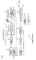
- Fig. 1 is a block diagram illustrating the schematic construction of the first embodiment of the projection display device according to the present invention.
- projection display device 1 comprises image processing unit 19 that executes image-display processing of the data of input image 18; projection lens 20 adapted to projection of a display image processed by image processing unit 19 onto screen 5 to provide an enlarged presentation of the projected display image (a video picture); test-pattern projection unit 22 that projects test pattern 131 onto screen 5 through projection lens 20; imaging unit 11 provided with imaging element 111 that shoots the projected video picture and also with photograph lens 112; shot-image analysis unit 9 that analyses shot images provided from imaging unit 11 and detects obstacle 7 represented within the region of the video picture; image mask generation unit 16 that generates an image mask corresponding to detected obstacle 7; and luminance control unit 17 that controls luminance corresponding to the image mask; wherein image mask generation unit 16 includes image-mask enlargement-processing unit 161 that generates image mask section 31 having a larger region than the region of detected obstacle 7.
- Shot-image analysis unit 9 comprises frame memory 13 that stores a shot image of test pattern 131 for cases where an obstacle is not present within the region of the projected video picture; comparison unit 14 that compares a shot image of test pattern 131 for the case where an obstacle is present in the region of the projected video picture with the shot image of test pattern 131 stored in frame memory 13; obstacle detection unit 15 that detects obstacle 7 based on the comparison result; and test pattern acquisition switch 12 that, through a switching operation, permits transferring the shot image of test pattern 131 shot by imaging unit 11 to frame memory 13 for cases where obstacle 7 is not present in the region of the projected video picture, and shuts off the shot image of test pattern 131, for cases where obstacle 7 is present in the region of the projected video picture, from being transferred to frame memory 13.
- projection display device 1 constructed as described above, is explained with reference to the drawings.
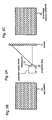
- Fig. 2A illustrates an example of using projection display device 1 for cases where there is no obstacle 7 between projection display device 1 and screen 5;
- Fig. 2B illustrates test pattern 131; and
- Fig. 2C illustrates shot image 61 shot by imaging unit 11.
- Fig. 3A illustrates an example of using projection display device 1 for cases where there is obstacle 7 between projection display device 1 and screen 5;
- Fig. 3B illustrates test pattern 131; and
- Fig. 3C illustrates shot image 62 shot by imaging unit 11.
- test pattern 131 has a straight horizontal pattern and is depicted by an infrared beam, the pattern positioned in the direction perpendicular to the straight line that connects projection lens 20 and imaging unit 11.
- the video picture when shot by imaging element 111, has the shape of a simple straight line as shot image 61 shown in Fig. 2C.
- the image shot by imaging element 111 has the pattern of shot image 62 as shown in Fig. 3C, straight lines corresponding to the location of obstacle 7 that shift from the straight lines corresponding to the picture of the test pattern projected on to screen 5.
- This shift is a phenomenon that arises from the arrangement of projection lens 20 which shifted from the location of imaging unit 11.
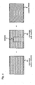
- Fig. 4 represents a diagram to illustrate the method for detecting the position of obstacle 7.
- comparison unit 14 finds a difference between the position of shot image 61 of test pattern 131 (cf. Fig. 2C), for cases where obstacle 7 is not represented (pictured) in the region of the projected video picture (the data of shot image 61 being stored in frame memory 13) and the position of shot image 62 of test pattern 131 (cf. Fig. 3C), for cases where obstacle 7 is represented in the region of the projected video picture; and obstacle detection unit 15 binarizes the found difference and calculates detected image 8.
- obstacle detection unit 15 subtracts the luminance of shot image 62 from the luminance of shot image 61 for each pixel, and if the subtraction result is a minus value, then the subtraction result is put as zero.
- the image obtained as a result of the calculation is represented in a binarized representation of black and white, thereby yielding detected image 8.
- image mask generation unit 16 After the generation of detected image 8, image mask generation unit 16 produces image mask 30 corresponding to the detected image of obstacle 7.
- Image-mask enlargement-processing unit 161 produces an image mask section 31 having a region lager than the region of detected image 8 of obstacle 7.
- Luminance control unit 17 controls and reduces the luminance in image mask section 31.
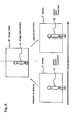
- Fig. 5 is a diagram to illustrate the operations of the projection display device when a person enters the area between the projection display device and screen 5 and moves within this area.
- obstacle detection unit 15 effects the detection of obstacle at the location of the person (before movement) 51, deeming it as obstacle 7 and makes image mask 30 based on the detection information.
- image-mask enlargement-processing unit 161 magnifies the dimension of detected image 8 of the obstacle included in the detection information in both right and left directions to form image mask 30 inclusive of image mask section 31.
- the person 52 can be protected from being irradiated by high luminance by reducing the luminance of the video picture to be projected to the region of this image mask section 31 even when the person moves to the position of the person 52 (after movement), because person 52 is present in the region where the luminance of the projected video picture falls, so that safety for a human body (an eye) in motion is ensured.
- image mask 40 When a person moves right in Fig. 6 as time progresses, the detection of the obstacle occurs at the position before movement of person 51, and image mask 40 is generated based on the detection information.
- image mask 40 which has image mask section 41, is formed based upon the dimensions described in the information for detected image 8, and the luminance of the video picture which is to be projected to the region which corresponds to the region of image mask section 41, is reduced.
- the amount of irradiation is based upon the person's movement, and the result is an inability to ensure safety (of the person).
- image mask section 31 is enlarged in the horizontal direction in the embodiment shown in Fig. 5, it should be pointed out that ensuring safety is feasible by enlarging image mask section 31 in the vertical direction and by anticipating if human actions that entail movements in the vertical direction such as romping and jumping. The explanation is herein omitted.
- enlarging image mask section 31 by 80 dots, which is an increase above 77 dots, in each of the right and left directions makes it possible to sufficiently reduce the luminance of the pixels that cover the range of movements of the person, thereby preventing irradiation of the person by high luminance, whereby the safety of a person in motion is ensured even when he is moving in the region of the projected video picture.
- the number of dots to be enlarged can be fixed at a sufficient value to ensure the safety of the person.
Landscapes
- Engineering & Computer Science (AREA)
- Multimedia (AREA)
- Signal Processing (AREA)
- Projection Apparatus (AREA)
- Transforming Electric Information Into Light Information (AREA)
- Controls And Circuits For Display Device (AREA)
- Control Of Indicators Other Than Cathode Ray Tubes (AREA)
Applications Claiming Priority (2)
| Application Number | Priority Date | Filing Date | Title |
|---|---|---|---|
| JP2003335976 | 2003-09-26 | ||
| JP2003335976A JP3735624B2 (ja) | 2003-09-26 | 2003-09-26 | 投影表示装置 |
Publications (2)
| Publication Number | Publication Date |
|---|---|
| EP1519574A2 true EP1519574A2 (de) | 2005-03-30 |
| EP1519574A3 EP1519574A3 (de) | 2005-11-16 |
Family
ID=34191531
Family Applications (1)
| Application Number | Title | Priority Date | Filing Date |
|---|---|---|---|
| EP04022442A Withdrawn EP1519574A3 (de) | 2003-09-26 | 2004-09-21 | Projektionsanzeigevorrichtung |
Country Status (4)
| Country | Link |
|---|---|
| US (1) | US7210786B2 (de) |
| EP (1) | EP1519574A3 (de) |
| JP (1) | JP3735624B2 (de) |
| CN (1) | CN100447661C (de) |
Cited By (2)
| Publication number | Priority date | Publication date | Assignee | Title |
|---|---|---|---|---|
| CN101799617B (zh) * | 2009-02-06 | 2012-05-23 | 精工爱普生株式会社 | 点亮控制装置及投影机 |
| CN112235553A (zh) * | 2020-10-12 | 2021-01-15 | 歌尔科技有限公司 | 投影亮度调整方法、装置、投影设备及可读存储介质 |
Families Citing this family (41)
| Publication number | Priority date | Publication date | Assignee | Title |
|---|---|---|---|---|
| JP3741136B2 (ja) * | 2004-04-08 | 2006-02-01 | 松下電器産業株式会社 | 障害物適応投射型表示装置 |
| KR20250158511A (ko) * | 2024-04-30 | 2025-11-06 | 삼성전자주식회사 | 프로젝터 및 그 제어 방법 |
| US7325933B2 (en) * | 2004-08-09 | 2008-02-05 | Sanyo Electric Co., Ltd | Projection type video display apparatus |
| US8508710B2 (en) * | 2004-12-02 | 2013-08-13 | Hewlett-Packard Development Company, L.P. | Display panel |
| JP2006330447A (ja) * | 2005-05-27 | 2006-12-07 | Mitsubishi Electric Corp | フロントプロジェクタ装置 |
| WO2006137548A1 (ja) * | 2005-06-24 | 2006-12-28 | Matsushita Electric Industrial Co., Ltd. | 画像投射装置及び背面投写型ディスプレイ装置 |
| KR20070079831A (ko) * | 2006-02-03 | 2007-08-08 | 삼성전자주식회사 | 디스플레이장치 및 그 제어방법 |
| JP5023587B2 (ja) * | 2006-07-18 | 2012-09-12 | 富士ゼロックス株式会社 | 画像表示装置及び画像表示方法 |
| US7891818B2 (en) | 2006-12-12 | 2011-02-22 | Evans & Sutherland Computer Corporation | System and method for aligning RGB light in a single modulator projector |
| US20080224041A1 (en) * | 2007-03-16 | 2008-09-18 | Cannamela John J | Method and apparatus for subsurface anomaly detection and image projection |
| JP4726851B2 (ja) * | 2007-04-20 | 2011-07-20 | シャープ株式会社 | 電子機器 |
| WO2008144749A1 (en) * | 2007-05-21 | 2008-11-27 | Evans & Sutherland Computer Corporation | Invisible scanning safety system |
| JP4341723B2 (ja) * | 2008-02-22 | 2009-10-07 | パナソニック電工株式会社 | 光投影装置、照明装置 |
| US8358317B2 (en) | 2008-05-23 | 2013-01-22 | Evans & Sutherland Computer Corporation | System and method for displaying a planar image on a curved surface |
| JP4409618B2 (ja) * | 2008-06-04 | 2010-02-03 | 暁 吉井 | 全視野投影装置および全視野映像システム |
| US8702248B1 (en) | 2008-06-11 | 2014-04-22 | Evans & Sutherland Computer Corporation | Projection method for reducing interpixel gaps on a viewing surface |
| US8077378B1 (en) | 2008-11-12 | 2011-12-13 | Evans & Sutherland Computer Corporation | Calibration system and method for light modulation device |
| US8290208B2 (en) * | 2009-01-12 | 2012-10-16 | Eastman Kodak Company | Enhanced safety during laser projection |
| US20120092630A1 (en) * | 2009-07-31 | 2012-04-19 | Kunitaka Furuichi | Projection type display device and light amount adjustment method |
| CN101795375B (zh) * | 2009-12-30 | 2012-07-18 | 广东威创视讯科技股份有限公司 | 投影显示装置及投影控制方法 |
| CN102193287B (zh) * | 2010-03-11 | 2013-03-20 | 宏碁股份有限公司 | 投影方法与投影系统 |
| US8733951B2 (en) * | 2010-04-26 | 2014-05-27 | Microsoft Corporation | Projected image enhancement |
| EP2407803A1 (de) * | 2010-07-15 | 2012-01-18 | The European Atomic Energy Community (EURATOM), represented by the European Commission | Verfahren zur sichereren Identifizierung beweglicher Objekte |
| CN102375309A (zh) * | 2010-08-26 | 2012-03-14 | 鸿富锦精密工业(深圳)有限公司 | 投影机光线调整系统及方法 |
| WO2012122679A1 (zh) * | 2011-03-16 | 2012-09-20 | Chen Chih-Hsiao | 激光投影系统的人眼安全保护系统 |
| CN102681312B (zh) * | 2011-03-16 | 2015-06-24 | 宏瞻科技股份有限公司 | 激光投影系统的人眼安全保护系统 |
| US9641826B1 (en) | 2011-10-06 | 2017-05-02 | Evans & Sutherland Computer Corporation | System and method for displaying distant 3-D stereo on a dome surface |
| WO2013186993A1 (ja) * | 2012-06-15 | 2013-12-19 | 日本電気株式会社 | 投射型投影装置、光防眩方法、および光防眩用プログラム |
| CN102914936B (zh) * | 2012-09-20 | 2016-02-17 | 深圳雅图数字视频技术有限公司 | 投影机的控制方法和装置 |
| CN104349215A (zh) * | 2013-08-08 | 2015-02-11 | 联想(北京)有限公司 | 一种切换方法和第一电子设备 |
| CN105072430B (zh) * | 2015-08-19 | 2017-10-03 | 海信集团有限公司 | 一种调整投影图像的方法和设备 |
| EP3502647A4 (de) * | 2016-08-18 | 2019-12-18 | QD Laser, Inc. | Bildinspektionsvorrichtung, bildinspektionsverfahren und bildinspektionsvorrichtungskomponente |
| CN106507071A (zh) * | 2016-09-20 | 2017-03-15 | 青岛海信电器股份有限公司 | 一种输出图像处理方法及设备 |
| JP6828747B2 (ja) * | 2016-09-21 | 2021-02-10 | 日本電気株式会社 | 投射システム、投射方法およびプログラム |
| CN107205141B (zh) * | 2017-07-24 | 2019-12-17 | 合肥联宝信息技术有限公司 | 一种投影控制方法及投影设备 |
| JP7059635B2 (ja) * | 2018-01-10 | 2022-04-26 | 凸版印刷株式会社 | 投影画像制御装置、投影画像制御システム、及び投影画像制御方法 |
| CN109031868B (zh) * | 2018-07-26 | 2020-09-22 | 漳州万利达科技有限公司 | 一种带眼睛防护功能的超短焦桌面投影仪 |
| TWI678926B (zh) | 2018-09-25 | 2019-12-01 | 華碩電腦股份有限公司 | 投影方法及投影系統 |
| WO2020210841A1 (en) * | 2019-04-12 | 2020-10-15 | Daniel Seidel | Projection system with interactive exclusion zones and topological adjustment |
| CN111292316B (zh) * | 2020-03-11 | 2023-09-01 | 成都极米科技股份有限公司 | 测试方法、装置、电子设备及存储介质 |
| JP2021189222A (ja) * | 2020-05-26 | 2021-12-13 | セイコーエプソン株式会社 | プロジェクターの制御方法及びプロジェクター |
Family Cites Families (12)
| Publication number | Priority date | Publication date | Assignee | Title |
|---|---|---|---|---|
| JP3240073B2 (ja) | 1992-09-18 | 2001-12-17 | 富士写真光機株式会社 | 投影機能を備えた電子ビューファインダ |
| DE19640404A1 (de) | 1996-09-30 | 1998-04-09 | Ldt Gmbh & Co | Vorrichtung zur Darstellung von Bildern |
| JP2000194302A (ja) | 1998-12-28 | 2000-07-14 | Brother Ind Ltd | 投影表示装置 |
| JP3630015B2 (ja) | 1999-04-21 | 2005-03-16 | セイコーエプソン株式会社 | 投写型表示装置及び情報記憶媒体 |
| US6554431B1 (en) * | 1999-06-10 | 2003-04-29 | Sony Corporation | Method and apparatus for image projection, and apparatus controlling image projection |
| JP4192400B2 (ja) | 1999-12-28 | 2008-12-10 | ソニー株式会社 | 画像投射方法及び画像投射装置 |
| JP3678111B2 (ja) | 2000-04-25 | 2005-08-03 | セイコーエプソン株式会社 | プロジェクタから射出される投射光の経路内に人が進入した場合の光束制御 |
| US6361173B1 (en) * | 2001-02-16 | 2002-03-26 | Imatte, Inc. | Method and apparatus for inhibiting projection of selected areas of a projected image |
| JP3704706B2 (ja) | 2002-03-13 | 2005-10-12 | オムロン株式会社 | 三次元監視装置 |
| JP4374825B2 (ja) | 2002-04-17 | 2009-12-02 | 栗田工業株式会社 | 晶析脱リン方法 |
| US6789903B2 (en) | 2003-02-18 | 2004-09-14 | Imatte, Inc. | Generating an inhibit signal by pattern displacement |
| JP3849654B2 (ja) | 2003-02-21 | 2006-11-22 | 株式会社日立製作所 | 投射型表示装置 |
-
2003
- 2003-09-26 JP JP2003335976A patent/JP3735624B2/ja not_active Expired - Fee Related
-
2004
- 2004-09-15 US US10/940,611 patent/US7210786B2/en not_active Expired - Lifetime
- 2004-09-21 EP EP04022442A patent/EP1519574A3/de not_active Withdrawn
- 2004-09-21 CN CNB200410082608XA patent/CN100447661C/zh not_active Expired - Fee Related
Non-Patent Citations (1)
| Title |
|---|
| None * |
Cited By (2)
| Publication number | Priority date | Publication date | Assignee | Title |
|---|---|---|---|---|
| CN101799617B (zh) * | 2009-02-06 | 2012-05-23 | 精工爱普生株式会社 | 点亮控制装置及投影机 |
| CN112235553A (zh) * | 2020-10-12 | 2021-01-15 | 歌尔科技有限公司 | 投影亮度调整方法、装置、投影设备及可读存储介质 |
Also Published As
| Publication number | Publication date |
|---|---|
| US7210786B2 (en) | 2007-05-01 |
| US20050068500A1 (en) | 2005-03-31 |
| JP2005109540A (ja) | 2005-04-21 |
| JP3735624B2 (ja) | 2006-01-18 |
| EP1519574A3 (de) | 2005-11-16 |
| CN1601370A (zh) | 2005-03-30 |
| CN100447661C (zh) | 2008-12-31 |
Similar Documents
| Publication | Publication Date | Title |
|---|---|---|
| US7210786B2 (en) | Projection display device | |
| CN114205570A (zh) | 一种投影设备及自动校正投影图像的显示控制方法 | |
| US6984039B2 (en) | Laser projector having silhouette blanking for objects in the output light path | |
| JP3885458B2 (ja) | 投写画像の校正方法及びその装置、並びに機械可読媒体 | |
| JP5680976B2 (ja) | 電子黒板システム及びプログラム | |
| JPH113429A (ja) | 観察者トラッキング自動立体表示装置、画像トラッキングシステム、および画像トラッキング方法 | |
| KR20040081022A (ko) | 화상 처리 시스템, 프로젝터 및 화상 처리 방법 | |
| CN118541967A (zh) | 一种投影设备和校正方法 | |
| CN113286135A (zh) | 图像校正方法及设备 | |
| CN118104229A (zh) | 一种投影设备及投影图像的显示控制方法 | |
| CN114885142B (zh) | 一种投影设备及调节投影亮度方法 | |
| CN112954285A (zh) | 投影画面的显示方法以及激光投影设备 | |
| US10812764B2 (en) | Display apparatus, display system, and method for controlling display apparatus | |
| CN113301317B (zh) | 投影画面的显示方法以及激光投影设备 | |
| US7119788B2 (en) | Image processing apparatus, image processing method, providing medium and presentation system | |
| CN104657702A (zh) | 眼球侦测装置、瞳孔侦测方法与虹膜辨识方法 | |
| CN114928728B (zh) | 投影设备及异物检测方法 | |
| JP2005091665A (ja) | プロジェクタ及び障害物検出方法 | |
| JP7248527B2 (ja) | 投射型映像表示装置および障害物検出方法 | |
| CN119788824B (zh) | 投影设备和投影控制方法 | |
| CN119788823B (zh) | 投影设备和投影控制方法 | |
| US20250024005A1 (en) | Real time masking of projected visual media | |
| JP2020123867A (ja) | 画像投射システム及び投射領域の検出方法 | |
| JPH05233148A (ja) | 座標入力機能付プロジェクタ装置 | |
| CN119922289A (zh) | 一种投影设备及防射眼投影方法 |
Legal Events
| Date | Code | Title | Description |
|---|---|---|---|
| PUAI | Public reference made under article 153(3) epc to a published international application that has entered the european phase |
Free format text: ORIGINAL CODE: 0009012 |
|
| AK | Designated contracting states |
Kind code of ref document: A2 Designated state(s): AT BE BG CH CY CZ DE DK EE ES FI FR GB GR HU IE IT LI LU MC NL PL PT RO SE SI SK TR |
|
| AX | Request for extension of the european patent |
Extension state: AL HR LT LV MK |
|
| PUAL | Search report despatched |
Free format text: ORIGINAL CODE: 0009013 |
|
| AK | Designated contracting states |
Kind code of ref document: A3 Designated state(s): AT BE BG CH CY CZ DE DK EE ES FI FR GB GR HU IE IT LI LU MC NL PL PT RO SE SI SK TR |
|
| AX | Request for extension of the european patent |
Extension state: AL HR LT LV MK |
|
| 17P | Request for examination filed |
Effective date: 20051006 |
|
| AKX | Designation fees paid |
Designated state(s): DE FR GB |
|
| 17Q | First examination report despatched |
Effective date: 20070309 |
|
| RAP1 | Party data changed (applicant data changed or rights of an application transferred) |
Owner name: NEC DISPLAY SOLUTIONS, LTD. |
|
| STAA | Information on the status of an ep patent application or granted ep patent |
Free format text: STATUS: THE APPLICATION IS DEEMED TO BE WITHDRAWN |
|
| 18D | Application deemed to be withdrawn |
Effective date: 20140401 |