EP1519862B1 - Balai d'essuie-glace - Google Patents
Balai d'essuie-glace Download PDFInfo
- Publication number
- EP1519862B1 EP1519862B1 EP03761402A EP03761402A EP1519862B1 EP 1519862 B1 EP1519862 B1 EP 1519862B1 EP 03761402 A EP03761402 A EP 03761402A EP 03761402 A EP03761402 A EP 03761402A EP 1519862 B1 EP1519862 B1 EP 1519862B1
- Authority
- EP
- European Patent Office
- Prior art keywords
- wiper
- wiper blade
- pivot pin
- cap
- rod
- Prior art date
- Legal status (The legal status is an assumption and is not a legal conclusion. Google has not performed a legal analysis and makes no representation as to the accuracy of the status listed.)
- Expired - Lifetime
Links
- 210000000078 claw Anatomy 0.000 claims description 22
- 239000002184 metal Substances 0.000 claims description 22
- 230000002349 favourable effect Effects 0.000 description 3
- 238000003860 storage Methods 0.000 description 3
- 238000000034 method Methods 0.000 description 2
- 239000004033 plastic Substances 0.000 description 2
- 229910000639 Spring steel Inorganic materials 0.000 description 1
- 238000005452 bending Methods 0.000 description 1
- 238000013016 damping Methods 0.000 description 1
- 238000009826 distribution Methods 0.000 description 1
- 230000000694 effects Effects 0.000 description 1
- 230000005489 elastic deformation Effects 0.000 description 1
- 239000004744 fabric Substances 0.000 description 1
- 238000009434 installation Methods 0.000 description 1
- 238000003825 pressing Methods 0.000 description 1
- 238000011144 upstream manufacturing Methods 0.000 description 1
- 230000000007 visual effect Effects 0.000 description 1
- 238000003466 welding Methods 0.000 description 1
Images


Classifications
-
- B—PERFORMING OPERATIONS; TRANSPORTING
- B60—VEHICLES IN GENERAL
- B60S—SERVICING, CLEANING, REPAIRING, SUPPORTING, LIFTING, OR MANOEUVRING OF VEHICLES, NOT OTHERWISE PROVIDED FOR
- B60S1/00—Cleaning of vehicles
- B60S1/02—Cleaning windscreens, windows or optical devices
- B60S1/04—Wipers or the like, e.g. scrapers
- B60S1/32—Wipers or the like, e.g. scrapers characterised by constructional features of wiper blade arms or blades
- B60S1/40—Connections between blades and arms
- B60S1/4067—Connections between blades and arms for arms provided with a side pin
-
- B—PERFORMING OPERATIONS; TRANSPORTING
- B60—VEHICLES IN GENERAL
- B60S—SERVICING, CLEANING, REPAIRING, SUPPORTING, LIFTING, OR MANOEUVRING OF VEHICLES, NOT OTHERWISE PROVIDED FOR
- B60S1/00—Cleaning of vehicles
- B60S1/02—Cleaning windscreens, windows or optical devices
- B60S1/04—Wipers or the like, e.g. scrapers
- B60S1/32—Wipers or the like, e.g. scrapers characterised by constructional features of wiper blade arms or blades
- B60S1/38—Wiper blades
- B60S1/3848—Flat-type wiper blade, i.e. without harness
- B60S1/3849—Connectors therefor; Connection to wiper arm; Attached to blade
- B60S1/3851—Mounting of connector to blade assembly
- B60S1/3856—Gripping the blade
-
- B—PERFORMING OPERATIONS; TRANSPORTING
- B60—VEHICLES IN GENERAL
- B60S—SERVICING, CLEANING, REPAIRING, SUPPORTING, LIFTING, OR MANOEUVRING OF VEHICLES, NOT OTHERWISE PROVIDED FOR
- B60S1/00—Cleaning of vehicles
- B60S1/02—Cleaning windscreens, windows or optical devices
- B60S1/04—Wipers or the like, e.g. scrapers
- B60S1/32—Wipers or the like, e.g. scrapers characterised by constructional features of wiper blade arms or blades
- B60S1/40—Connections between blades and arms
- B60S1/4083—Connections between blades and arms for arms provided with a flat end
-
- B—PERFORMING OPERATIONS; TRANSPORTING
- B60—VEHICLES IN GENERAL
- B60S—SERVICING, CLEANING, REPAIRING, SUPPORTING, LIFTING, OR MANOEUVRING OF VEHICLES, NOT OTHERWISE PROVIDED FOR
- B60S1/00—Cleaning of vehicles
- B60S1/02—Cleaning windscreens, windows or optical devices
- B60S1/04—Wipers or the like, e.g. scrapers
- B60S1/32—Wipers or the like, e.g. scrapers characterised by constructional features of wiper blade arms or blades
- B60S1/38—Wiper blades
- B60S1/3806—Means, or measures taken, for influencing the aerodynamic quality of the wiper blades
-
- B—PERFORMING OPERATIONS; TRANSPORTING
- B60—VEHICLES IN GENERAL
- B60S—SERVICING, CLEANING, REPAIRING, SUPPORTING, LIFTING, OR MANOEUVRING OF VEHICLES, NOT OTHERWISE PROVIDED FOR
- B60S1/00—Cleaning of vehicles
- B60S1/02—Cleaning windscreens, windows or optical devices
- B60S1/04—Wipers or the like, e.g. scrapers
- B60S1/32—Wipers or the like, e.g. scrapers characterised by constructional features of wiper blade arms or blades
- B60S1/40—Connections between blades and arms
- B60S1/4067—Connections between blades and arms for arms provided with a side pin
- B60S1/4074—Connections between blades and arms for arms provided with a side pin with means provided on the blade for locking the side pin
Definitions
- the invention is based on a wiper blade according to the preamble of claim 1.
- wipers have a wiper arm, which sits on a wiper shaft. This is driven by a wiper motor.
- a wiper blade is hinged to the free end of the wiper arm. It usually has a Hatgliediges mounting bracket system with a center bracket. At this subordinate bracket are hinged, of which at least some hold with claws at their ends a wiper strip.
- jointless wiper blades which have a perpendicular to the vehicle window resilient, elastic support member, which is made of plastic instead of the support bracket system. To improve the spring characteristic, it may have at least one spring rail of spring steel. The support member has a stronger curvature in the unloaded state than the vehicle window, so that the wiper strip under the contact force of the wiper arm with a suitable pressure distribution to the vehicle window applies.
- a windshield wiper with a jointless wiper blade is known, which is hingedly connected to a wiper arm via a so-called "sidelock system".
- a two-part connector whose first part has a block-shaped portion with a bearing bore and which includes integrally formed form-locking elements serving as a support element spring strips laterally and from below.
- the second part is fixed to the free end of the wiper arm, which has a vehicle window towards the open, U-shaped profile.
- a pin is laterally and transversely to the longitudinal direction of the wiper arm and pointing to the wiper blade inserted into the second part and pivotally mounted in the bearing bore of the first part of the connecting piece.
- a bridge is arranged offset in the longitudinal direction of the second part of the connector, which is angled at its free end to the side of the pin out.
- the pin In a mounting position, in which the wiper blade is held transversely to the longitudinal direction of the wiper arm, the pin can be pushed into the bearing bore of the connecting part. If the wiper blade is then rotated parallel to the longitudinal direction of the wiper arm, the bridge engages over the wiper blade and locks it with its angled end, so that lateral guide surfaces of the block-shaped portion of the first part of the connector in the assembled state between the angled Are stirred at the end of the bridge and an opposite surface of the second part.
- the bridge dips in the operating position of the wiper blade in a corresponding groove of the first part and includes approximately flush with the top of it.
- the wiper blade For disassembly, the wiper blade must be swung in the opposite direction until the angled end is disengaged and the wiper blade can be pulled from the pin.
- a wiper device for windows of motor vehicles has a wiper blade to which a pivot pin is firmly connected.
- the pivot pin extends in a plane that is substantially parallel to the vehicle window, and is rotatably mounted in a bearing bore of the wiper arm. So that the pivot pin does not slide out of the bearing bore during a wiping movement, the wiper blade is locked in the axial direction of the pivot pin with respect to the wiper arm by an extension of the wiper arm projecting projection engages in a groove of a projection which is fixedly connected laterally by the wiper blade with this. The outer edge of the groove forms a shoulder against which the projection rests in the operating position and thus locks the wiper blade axially to the pivot pin.
- the joint comprises a cap, which covers the connecting part and is secured thereto.
- the cap secures the wiper blade and the Wiper rod in the mounted position.
- This achieves a very flat connection between a preferably jointless wiper blade and a wiper rod, wherein the connecting parts for left-hand drive vehicles and right-hand drive vehicles are the same. Only the wiper rod is mirror-inverted.
- the design according to the invention allows numerous variants with free spaces for design design, so that the wiper blade can be adapted to numerous vehicle types. Since most functions for adapting the windshield wiper to a motor vehicle are concentrated on the connecting part and the joint axle, the wiper rod can be kept simple.
- the cap has on its side to the wiper rod towards a bag which is open to the vehicle window and in the longitudinal direction of the wiper rod to this and laterally engages over.
- the pocket can be arranged in extension of the wiper rod, so that an extension of the wiper rod beyond the hinge axis engages in the operating position in the pocket of the cap.
- the pocket can also be arranged in front of the hinge axis, as viewed in the longitudinal direction, from the drive side of the wiper rod, wherein it comprises the wiper rod on the drive side to the hinge axis. This can make the cap and the wiper rod shorter.
- the wiper blade is pivoted by about 90 ° to the wiper rod, the extension of the wiper rod or the wiper rod itself leaves the pocket and the wiper blade can be removed from the joint axis attached to the wiper rod.
- the assembly takes place in the reverse direction.
- the cap may have a guide pin which is guided in a fork at the end of the wiper rod.
- a spoiler is usually placed on the support element on both sides of the connecting part.
- the cap connects the two parts of the spoiler harmoniously, by connecting with connecting sections to the parts, so that there is essentially a continuous spoiler with good flow conditions for the wind.
- the wiper rod has a flat, rectangular cross-sectional profile whose long side extends approximately parallel to the vehicle window, it supports the function of the spoiler, if it is arranged on the upstream side.
- the connecting part in the form of a sheet metal claw, can be made of metal or plastic. It has a parallel to the support element extending back, on the longitudinal sides for ease of installation locking lugs are formed so that it can be mecanicklippst across the support element.
- the connecting part has two side cheeks. They have receiving openings for the hinge axis and are interconnected by a bearing tube when the hinge axis is rotatably mounted in the connecting part.
- the side cheeks have for easy mounting of the cap locking recesses or detent holes, engage in the locking lugs of the cap.
- the cap can be held by a clip that includes the bearing tube.
- the cap can be secured by projecting a free end of the hinge axle over the side wall and engaging a recess in the side wall of the cap.
- the wiper rod can extend above the joint axis, in the same plane as the joint axis or below the joint axis.
- the end projecting beyond the hinge axis is angled or bevelled to the rubber profile of the wiper blade, so that the cap can be made lower with its pocket.
- the wiper rod can be straight. It produces particularly favorable inflow conditions, since it extends the lower side of the spoiler profile and has only a small distance to the vehicle window.
- the articulated axle is rotatably mounted in the connecting part, it is firmly connected to the wiper rod at an end protruding from the connecting part. This can be done by fabric closure, z. B. by welding, by form or adhesion, z. B. by riveting, pressing or the like. Take place.
- the hinge axis at its end, which is associated with the wiper rod, a flat head, are provided in the rivet holes for rivets.
- the wiper rod has corresponding rivet holes and is riveted to the hinge axis.
- the hinge axis has a flat head, on which a transversely to the hinge axis projecting polygon, z. B. a three, four or hexagon is formed, which is pressed into a corresponding opening of the wiper rod and secured at its protruding end by wobble rivets.
- Tumbling riveting is a riveting method in which the riveting tool rollovers during riveting. Before assembly, the wiper rods and heads of the joint axles are painted black.
- the hinge axis has a head with a slot for receiving the flat wiper rod, which is secured by a transverse pin or a rivet in the slot.
- the wiper rod in the region of the hinge axis may have a hub, which comprises the hinge axis and is secured by a transverse pin on this.
- the flat wiper rod is twisted at its end by about 90 °, so that a broad side of one end is transverse to the hinge axis.
- the end has a receiving bore for a hinge axis with a collar, which is followed by a knurled seat, on which the receiving bore is pressed and is secured by a caulked disc.
- the projecting beyond the hinge axis end is bevelled towards the rubber profile of the wiper blade and engages in an associated pocket of the cap.
- This version has a short length of the joint axis. Nevertheless, the favorable position of the wiper rod to the spoiler remains in the majority of the wiper rod.
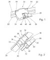
- a hingeless wiper blade 20 has a rubber profile 22 which is secured to a flat support member 24. This usually consists of one or two spring strips, which are embedded in the upper part of the rubber profile 22.
- a joint 30 is provided in the central region of the wiper blade 20. This has as a connecting part a metal claw 32, the back 34 spans the support member 24 and is secured with locking lugs 36 thereto.
- the locking lugs 36 can be pushed over the support element 24 in the longitudinal direction or be formed as a clip connection and be clipped by elastic deformation transverse to the support member 24.
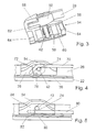
- the locking lugs 36 which are provided laterally at the ends of the sheet metal claw 32, are on the longitudinal sides 66 of the sheet metal claw 32 side walls 38 away from the rubber profile 22 from. They hold a bearing tube 40 which extends transversely to the wiper blade 20 and approximately parallel to a vehicle window, not shown. In the bearing tube 40, a hinge axis 42 is inserted, which protrudes on one side to the wiper rod 28 with a head 44 from the bearing tube 40.
- the wiper rod 28 has a rectangular cross-section, wherein the longer sides extend approximately parallel to the hinge axis 42. In the embodiments according to FIGS. 1 to 3, the wiper rod 28 engages in a slot 46 of the head 44 of the articulation axis 42 and is secured by a transverse pin 48. The wiper rod 28 projects beyond the slot 46 with a finger 52. The finger 52 is narrower than the wiper rod 28 and lies on the wiper blade 20 facing side of the wiper rod 28th
- the sheet metal claw 32 is covered by a cap 54 which connects with connection profiles 64 harmoniously to the parts of the spoiler 26.
- the cap 54 is releasably secured to the sheet metal claw 32.
- it has on the inside of its side walls 60 latching lugs 56 which engage in corresponding openings 104 (FIG. 11) or depressions of the sheet metal claw 32.
- it has in its central region a clip 58 for mounting on the bearing tube 40.
- the hinge axis 42 protrudes with its end facing away from the head 44 (FIG. 2) beyond the side wall 38, said end in a recess of the Side wall 60 of the cap 54 engages (Fig. 3) and thus supports their support on the sheet metal claw 32.
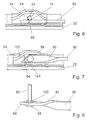
- the cap 54 has on the side of the wiper rod 28 a pocket 62 (FIG. 3) which is open toward the vehicle window and into which the finger 52 of the wiper rod 28 engages in the operating position in which the wiper blade 20 bears against the vehicle window.
- An outer wall 68 of the pocket 62 prevents the wiper rod 28 from moving outwardly with its finger 52, so that the hinge axle 42 is locked in the axial direction.
- the pocket 62 is largely covered by a cover 50 which sits on the hinge axis 42 and harmoniously connects to the contour of the wiper rod 28 and the cap 54.
- the cover 50 is simultaneously an impact protection or
- Damping element It prevents damage to the vehicle window if the wiper arm accidentally strikes the vehicle window when the wiper blade is changed.
- FIGS. 4 to 6 show wiper rods 70, 80, which are connected by welds 74 to one end of the hinge axis 42.
- the wiper rod 70 according to FIG. 4 extends above the articulation axis 42 and projects beyond the articulation axis 42 with an end 72 angled towards the rubber profile 22.
- the angled end 72 engages in the operating position of the wiper blade 20 shown in a pocket 76 of the cap 54, wherein the wiper arm 70 facing edge 78 of the cap 54 extends so that the wiper blade 20 in a direction of arrow rotated by approximately 90 ° position can be easily removed from the hinge axis 42.
- the wiper blade 20 is also mounted by being placed on the hinge axis 42 and then pivoted in the opposite direction.
- the wiper blades 20 according to FIGS. 1, 5 to 7, 10 and 11 are assembled and disassembled.
- the pocket 76 can be made flat, which reduces the wind resistance and improves the visual impression.
- a similar effect is achieved when the wiper rod 80 in the embodiments according to FIGS. 5 and 6 extends below the articulation axis 42 and engages with its straight end 82 extended beyond the articulation axis 42 into a pocket 84 of the cap 54.
- the edge 86 of the pocket 84 is formed so that in the pivoted mounting position assembly or disassembly is easily possible. While in the embodiments of FIGS. 4 and 5, the wiper blade 20 at the assembly must be rotated by about 90 °, the wiper blade 20 can be mounted and dismantled in the embodiment of FIG. 6 already at a smaller tilt angle. This is achieved in that the edge 88 of the pocket 84 extends at a smaller angle to the longitudinal direction of the wiper blade 20.
- the embodiment according to FIG. 7 enables a very narrow joint 30 in that the wiper rod 90 is set at its end 92 in the longitudinal direction by approximately 90 ° so that the longer sides of its rectangular profile run transversely to it in the area of the hinge axis 96.
- the protruding beyond the hinge axis 96 has a bevel end 94 which is inclined towards the rubber profile 22 and engages with the bevel 94 in a pocket 122 of the cap 54.
- the hinge axis 96 (FIG. 9) has a knurled seat 100, onto which the wiper rod 90 is pressed with a receiving opening up to a collar 98 and secured by a disc 102.
- the end of the wiper rods 118 protruding beyond the articulation axis 42 is designed as a fork 112, which in the illustrated operating position comprises a guide pin 116 of the cap 114.
- the fork 112 extends inclined towards the rubber profile 22.
- the wiper rod 118 according to FIG. 16 is inserted in a slot 46 of the head 44 of the articulated axle 42 and secured by a transverse pin 48
- the wiper rod 118 according to FIG. 11 has a hub 120, FIG. which sits on the free end of the hinge axis 42 and is secured by a transverse pin 48.
- the wiper rod 118 can also be welded to the hinge axis 42 like the wiper rods of the previously described embodiments.
- FIGS. 12 to 15 and 18 are similar to the embodiments according to FIGS. 5 and 6.
- the wiper rods 80 and 136 extend underneath the articulation axes 42 and 106 and 138.
- hinge axis 138 of FIGS. 14 and 15 has a flat head 140 with two rivet holes 142 connected by rivets 144 to wiper bar 136 (FIG. 15).
- the hinge axis 106 ( Figure 17) has a flat head 108 on which a square 110 is molded, which is press-fitted into a corresponding opening of the wiper rod 136 and optionally riveted in a tumbling process (Figure 18).
- the caps 54 for the embodiments according to FIGS. 12 to 15 and 18 have on the side to the wiper rod 80, 136 pockets 126, which comprise the wiper rod 80, 136 on their drive side in front of the hinge axis 42, 106, 138, then that the wiper rod 80, 136 does not have to protrude beyond the hinge axis 42, 106, 138.
- very flat wiper blades 20 can be achieved, wherein the cap 54 can be made very flat and closed.
- the hinge axis 178 (Fig. 20, 21) to the wiper rod 28, 90 towards two diametrically arranged wings 180, 182, which extend radially to the hinge axis 28, 90 and in the longitudinal direction of the associated wiper rod 28, 90.
- the hinge axis 178 of Figure 20 like the hinge axis 42 of Figure 1, has a slot 46 in a head 44 into which the wiper rod 28 is inserted and connected by a transverse pin, e.g. a rivet, is secured.
- the propeller shaft 178 according to FIG. 21 has a rivet pin 178 at the end, with which it is fastened to the wiper rod 90, which, like the wiper rod 90 according to FIG. 8, is rotated in the longitudinal direction by 90 °.
- the wings 180, 182 engage in the mounted position of the wiper blade 20 in correspondingly aligned pockets 184, 186 of a pocket 190 (FIG. 19) in the manner of a bayonet closure.
- the bayonet lock for disassembly can be solved or closed during assembly.
- the hinge axis 42, 96, 106, 138 rotatably mounted in the bearing tube 40 of the sheet metal claw 32 and connected to the wiper rod 20, 70, 80, 90, 118, 136
- the hinge axis 146, 164 rotatably with the metal claw 32 and rotatably connected to the wiper rod 150, for example by having a non-circular cross-sectional profile in the form of a polygon or flattened cylinder in corresponding openings of the side walls 38 is held.
- the articulation axis 146 has a semicircular cross-sectional profile with a flattening 148 which points to the rubber profile 22.
- a bearing sleeve 154 which has a cylindrical portion 156 at its outer periphery and the rubber profile 22 through a flattened portion 158 may have.
- a correspondingly bent end 152 of the wiper rod 150 is rotatably mounted (FIG. 23).
- the bent end 152 may also be mounted directly on a round or semi-circular profiled part of the propeller shaft 146, 164.
- the bearing sleeve 154 and the end 152 of the wiper rod 150 are guided in a bearing pocket 162 of a cap 160.
- the cap 160 is fastened by means of latching lugs 56 and a clip 58 on the sheet metal claw 32 and on the hinge axis 146.
- the hinge axis 146 protrudes beyond the bearing sleeve 154 and engages in a recess 176 of the cap 160.
- the wiper blade 20 can be mounted on the wiper rod 150 by turning it with the mounted cap 160 so far that the bent end 152 between the cap 160 and bearing sleeve 154 can be threaded.
- the variant according to FIG. 24 has a hinge axis 164 with a fastening region 166, which has a substantially rectangular cross section and a longitudinal section 168 extending transversely to the longer sides.
- the longer sides of the cross-sectional profile run approximately parallel to the support member 24.
- locking lugs 170 are provided at the ends of the mounting portion, through an opening in the associated side wall 38 protrude and lock with the edge of this opening.
- the hinge axis 164 on a storage area 172 which is bounded by two collars 174 in the axial direction.
- the bent end 152 of the wiper rod 150 is supported and secured by the bearing pocket 152 of the cap 160 in the mounted position.
Landscapes
- Engineering & Computer Science (AREA)
- Mechanical Engineering (AREA)
- Pivots And Pivotal Connections (AREA)
- Cleaning Implements For Floors, Carpets, Furniture, Walls, And The Like (AREA)
Claims (27)
- Balai d'essuie-glace (20) comportant une pièce de liaison (32) prévue sur un élément de support (24) du balai d'essuie-glace (20) et ayant une articulation (30) avec un axe d'articulation (42, 96, 106, 138, 146, 164, 178) dont l'extrémité libre est reliée à une tige d'essuie-glace (28, 70, 80, 90, 118, 136, 150),
caractérisé en ce que
l'articulation (30) comporte un capuchon (54, 114, 128, 160) couvrant la pièce de liaison (32) en étant fixé à celle-ci et retenant la tige d'essuie-glace (28, 70, 80, 90, 118, 136, 150) en position de montage du balai d'essuie-glace (20),
le capuchon (54, 114, 128, 160) ayant une poche (62, 76, 84, 122, 126, 164) en direction de la tige d'essuie-glace (28, 70, 80, 90, 118, 136, 150), cette poche étant ouverte en direction du pare-brise et dans la direction longitudinale de la tige d'essuie-glace (28, 70, 80, 90, 118, 136, 150) pour la couvrir latéralement. - Balai d'essuie-glace (20) selon la revendication 1,
caractérisé en ce qu'
un déflecteur (26) dont les parties rejoignent de façon harmonieuse le capuchon (54, 114, 128, 160, 190) avec une pièce de raccordement (64) est fixé sur l'élément de support (24), dans la direction longitudinale, des deux côtés de la pièce de liaison (32). - Balai d'essuie-glace (20) selon la revendication 2,
caractérisé en ce que
le capuchon (54, 114, 128, 160, 190) forme avec son profil de raccordement (64), un déflecteur (26) pratiquement continu. - Balai d'essuie-glace (20) selon la revendication 3,
caractérisé en ce que
le côté supérieur du capuchon (54, 114, 128, 160, 190) est relevé au niveau de son côté de fuite entre les profils de raccordement (64) (figure 1 et figure 4). - Balai d'essuie-glace (20) selon l'une des revendications 2 à 4,
caractérisé en ce que
le côté d'attaque du déflecteur (26) est tourné vers la tige d'essuie-glace (28). - Balai d'essuie-glace (20) selon l'une des revendications précédentes,
caractérisé en ce que
l'axe d'articulation (42, 96, 106, 138, 178) est monté à rotation dans la pièce de liaison (32) elle-même réalisée sous la forme d'une pince en tôle en étant fixée à l'élément de support (24) par des becs d'accrochage (36) prévus latéralement sur son dos (34). - Balai d'essuie-glace (20) selon la revendication 6,
caractérisé en ce que
la pince en tôle (32) possède des parois latérales (38) en saillie vers le haut sur ses grands côtés (66), ces parois latérales étant reliées par un tube de palier (40) recevant à rotation l'axe d'articulation (42, 96, 106, 138, 178) (figure 2). - Balai d'essuie-glace (20) selon l'une des revendications 6 ou 7,
caractérisé en ce que
le capuchon (54, 114, 128, 160, 190) est tenu par des becs d'encliquetage (56) à la pince en tôle (32), ces becs pénétrant dans des cavités d'encliquetage (104) des parois latérales (38) de la pince en tôle (32) (figure 11). - Balai d'essuie-glace (20) selon l'une des revendications 7 ou 8,
caractérisé en ce que
le capuchon (54, 114, 128, 160, 190) comporte un moyen d'encliquetage (58) au niveau du tube de palier (42), par lequel le capuchon est fixé au tube de palier (40) ou à l'axe d'articulation (164). - Balai d'essuie-glace (20) selon l'une des revendications 7 à 9,
caractérisé en ce qu'
une extrémité de l'axe d'articulation (42, 96, 106, 138, 146, 164, 190) dépasse d'une paroi latérale (38) de la pince en tôle (32) pour être reliée solidairement en rotation à la tige d'essuie-glace (28, 70, 80, 90, 118, 136) alors que son autre extrémité qui dépasse légèrement de la paroi latérale associée (38), pénètre dans une cavité du capuchon (54, 114, 128, 160, 190) (figure 2, figure 3 et figure 24). - Balai d'essuie-glace (20) selon l'une des revendications précédentes,
caractérisé en ce que
la tige d'essuie-glace (28, 70, 80, 90, 118) prolongée au-delà de l'axe d'articulation (42, 96) est guidée par la partie prolongée dans la poche (62, 76, 84, 122) ou par un goujon de guidage (116) du capuchon (54, 114) (figures 1 à 11). - Balai d'essuie-glace (20) selon la revendication 11,
caractérisé en ce que
la partie en saillie de la tige d'essuie-glace (28, 70, 80, 118) est recourbée en direction de la lame en caoutchouc (22). - Balai d'essuie-glace (20) selon l'une des revendications précédentes,
caractérisé en ce que
la tige d'essuie-glace (80, 136, 150) passe sous l'axe d'articulation (42, 106, 138, 146, 164) et au-dessus de la lame en caoutchouc (22). - Balai d'essuie-glace (20) selon l'une des revendications précédentes,
caractérisé en ce que
l'axe d'articulation (42, 96, 106, 138) est relié par un cordon de soudure (74) à la tige d'essuie-glace (28) (figures 4 à 6 et figure 11, figure 12). - Balai d'essuie-glace (20) selon l'une des revendications 1 à 13,
caractérisé en ce que
l'axe d'articulation (42, 178) possède une tête (44) ayant une fente (46) pour recevoir la tige d'essuie-glace (28, 118), fixée par l'intermédiaire d'une broche (48) dans la fente (46) (figure 1, figure 10, figure 20). - Balai d'essuie-glace (20) selon l'une des revendications 1 à 13,
caractérisé en ce que
l'extrémité de la tige d'essuie-glace (90) du côté de l'axe d'articulation (96) est tournée d'environ 90° autour de son axe longitudinal pour que son grand côté soit dirigé transversalement par rapport à l'axe d'articulation (96) (figure 8, figure 21). - Balai d'essuie-glace (20) selon la revendication 16,
caractérisé en ce que
l'axe d'articulation (96) s'appuie par une collerette (98) à son extrémité contre la tige d'essuie-glace (90), pressée sur un siège moleté (100) adjacent à la collerette (98) en étant retenue par une rondelle (102) (figure 8, figure 9). - Balai d'essuie-glace (20) selon l'une des revendications 16 ou 17,
caractérisé en ce que
la tige d'essuie-glace (90) dépasse par une extrémité, l'axe d'articulation (96), en ayant une partie en biais (94) dirigée vers la lame en caoutchouc (22) et qui, dans sa position de fonctionnement, pénètre dans la poche (122) du capuchon (54). - Balai d'essuie-glace (20) selon l'une des revendications 1 à 15,
caractérisé en ce que
le capuchon (114) comporte un goujon de guidage (116) dirigé latéralement vers la tige d'essuie-glace (118) et pénétrant dans l'extrémité en forme de fourche (112) de la tige d'essuie-glace (118) (figure 10, figure 11). - Balai d'essuie-glace (20) selon l'une des revendications précédentes,
caractérisé en ce que
la poche (126) du capuchon (128) se trouve entre l'axe d'articulation (42, 138) et l'extrémité d'entraînement de la tige d'essuie-glace (80, 136) en dépassant celle-ci latéralement (figure 12 à figure 14). - Balai d'essuie-glace (20) selon l'une des revendications précédentes,
caractérisé en ce que
l'axe d'articulation (138) possède du côté de la tige d'essuie-glace, une tête plate (140) avec deux orifices à rivet (142) pour être fixé par des rivets (144) à la tige d'essuie-glace (136) (figure 15). - Balai d'essuie-glace (20) selon l'une des revendications précédentes,
caractérisé en ce que
l'axe d'articulation (106) a une tête plate (108) munie d'une partie en saillie à quatre pans (110) transversale et enfoncée dans une ouverture adaptée de la tige d'essuie-glace (136), la partie en saillie étant rivetée par fluage radial (figure 18). - Balai d'essuie-glace (20) selon l'une des revendications précédentes,
caractérisé en ce que
l'axe d'articulation (178) comporte deux ailes (180, 182) diamétralement opposées, radiales par rapport à l'axe d'articulation (178) et s'étendant dans la direction longitudinale de la tige d'essuie-glace (28, 90) et qui se montent dans des cavités latérales (184, 186) du capuchon (190) alignées de manière correspondante, selon un assemblage de type baïonnette (figures 19 à 21). - Balai d'essuie-glace (20) selon l'une des revendications précédentes,
caractérisé en ce que
l'axe d'articulation (146) est tenu par un profil de section non circulaire dans des ouvertures correspondantes des parois latérales (38) de manière solidaire en rotation dans la pince en tôle (32) et sa partie en saillie reçoit en pivotement une extrémité recourbée (152) correspondante de la tige d'essuie-glace (150), cette extrémité étant guidée dans une poche de palier (162) du capuchon (160). - Balai d'essuie-glace (20) selon la revendication 24,
caractérisé en ce que
l'axe d'articulation (146) a un profil semi-rond avec un méplat (148) tourné vers la lame en caoutchouc (22) et bloqué solidairement en rotation dans des orifices correspondants des parois latérales (38) de la pince en tôle (32), la partie en saillie vers la tige d'essuie-glace (150) recevant une douille de palier (154) ayant une zone cylindrique (156) et une zone aplatie (158) adaptées, cette douille étant installée de manière solidaire en rotation, et portant de manière pivotante l'extrémité recourbée (152) de la tige d'essuie-glace (150) (figure 24). - Balai d'essuie-glace (20) selon la revendication 24,
caractérisé en ce que
l'axe d'articulation (146) pénètre par son extrémité libre dans une cavité (176) d'une paroi latérale de la poche de palier (162). - Balai d'essuie-glace (20) selon l'une des revendications 24 ou 26,
caractérisé en ce que
l'axe d'articulation (164) comporte une zone de palier (172) entre deux collerettes axiales (174) recevant la partie recourbée (152) de la tige d'essuie-glace (150) et une zone de fixation (166) à profil de section rectangulaire et une fente longitudinale (168) dont les extrémités des côtés extérieurs comportent des becs d'encliquetage (170) par lesquels cette zone de fixation est accrochée dans une ouverture correspondante des parois latérales associées (38) (figure 25 et figure 26).
Applications Claiming Priority (5)
| Application Number | Priority Date | Filing Date | Title |
|---|---|---|---|
| DE10229608 | 2002-06-28 | ||
| DE10229608 | 2002-06-28 | ||
| DE10259480 | 2002-12-19 | ||
| DE10259480A DE10259480A1 (de) | 2002-06-28 | 2002-12-19 | Wischblatt |
| PCT/DE2003/001638 WO2004002792A1 (fr) | 2002-06-28 | 2003-05-20 | Balai d'essuie-glace |
Publications (2)
| Publication Number | Publication Date |
|---|---|
| EP1519862A1 EP1519862A1 (fr) | 2005-04-06 |
| EP1519862B1 true EP1519862B1 (fr) | 2007-02-21 |
Family
ID=30001501
Family Applications (1)
| Application Number | Title | Priority Date | Filing Date |
|---|---|---|---|
| EP03761402A Expired - Lifetime EP1519862B1 (fr) | 2002-06-28 | 2003-05-20 | Balai d'essuie-glace |
Country Status (7)
| Country | Link |
|---|---|
| US (1) | US7546660B2 (fr) |
| EP (1) | EP1519862B1 (fr) |
| JP (1) | JP4295212B2 (fr) |
| BR (1) | BR0312013A (fr) |
| DE (1) | DE50306589D1 (fr) |
| ES (1) | ES2280795T3 (fr) |
| WO (1) | WO2004002792A1 (fr) |
Cited By (5)
| Publication number | Priority date | Publication date | Assignee | Title |
|---|---|---|---|---|
| US8806700B2 (en) | 2011-07-29 | 2014-08-19 | Pylon Manufacturing Corporation | Wiper blade connector |
| US9108595B2 (en) | 2011-07-29 | 2015-08-18 | Pylon Manufacturing Corporation | Windshield wiper connector |
| US9457768B2 (en) | 2011-04-21 | 2016-10-04 | Pylon Manufacturing Corp. | Vortex damping wiper blade |
| US9505380B2 (en) | 2014-03-07 | 2016-11-29 | Pylon Manufacturing Corp. | Windshield wiper connector and assembly |
| USD777079S1 (en) | 2014-10-03 | 2017-01-24 | Pylon Manufacturing Corp. | Wiper blade frame |
Families Citing this family (38)
| Publication number | Priority date | Publication date | Assignee | Title |
|---|---|---|---|---|
| DE10259480A1 (de) * | 2002-06-28 | 2004-01-15 | Robert Bosch Gmbh | Wischblatt |
| DE10259856B4 (de) * | 2002-12-20 | 2016-06-30 | Robert Bosch Gmbh | Wischerarm einer Wischvorrichtung für Scheiben von Kraftfahrzeugen |
| DE102004016017A1 (de) * | 2004-04-01 | 2005-10-20 | Bosch Gmbh Robert | Wischblatt |
| DE102004019157A1 (de) * | 2004-04-21 | 2005-11-10 | Robert Bosch Gmbh | Wischblatt |
| DE102004030429A1 (de) * | 2004-06-24 | 2006-01-19 | Valeo Wischersysteme Gmbh | Verbindung zwischen einem Wischarm und einem Wischblatt sowie Scheibenwischeranordnung |
| DE202005005406U1 (de) * | 2005-03-31 | 2006-01-19 | Karl Storz Gmbh & Co. Kg | Medizinisches Instrument mit konturiertem Achszapfen |
| CA2541641C (fr) | 2005-04-04 | 2014-02-11 | Trico Products Corporation | Raccord d'essuie-glace et essuie-glace ainsi equipe |
| US7774892B2 (en) | 2005-04-04 | 2010-08-17 | Trico Products Corporation | Wiper coupler and wiper assembly incorporating same |
| JP4641915B2 (ja) * | 2005-09-29 | 2011-03-02 | 株式会社ミツバ | ワイパブレード |
| DE102005050569A1 (de) * | 2005-10-21 | 2007-04-26 | Robert Bosch Gmbh | Anschlußvorrichtung für einen Wischerarm |
| DE102006004110A1 (de) * | 2006-01-28 | 2007-08-16 | Valeo Systèmes d`Essuyage | Wischarm |
| US20080028564A1 (en) * | 2006-08-04 | 2008-02-07 | Shu-Lan Ku | Wiper blade support structure |
| US8122560B2 (en) * | 2006-08-04 | 2012-02-28 | Dongguan Hongyi Wiper Co., Ltd. | Windshield wiper bridge base assembly |
| US8042218B2 (en) * | 2007-04-05 | 2011-10-25 | Trico Products Corporation | Wiper assembly having side-saddle coupler |
| DE102009001809A1 (de) * | 2009-03-24 | 2010-09-30 | Robert Bosch Gmbh | Anschlussvorrichtung zum gelenkigen Verbinden eines Wischarms mit einem Wischblatt nach einem Sidelockprinzip |
| KR101105340B1 (ko) * | 2009-08-21 | 2012-01-16 | 주식회사 캐프 | 차량용 와이퍼 블레이드의 금속재 클램프와 바디 스프링의 조립방법 |
| WO2011031516A2 (fr) | 2009-08-27 | 2011-03-17 | Trico Products Corporation | Ensemble essuie-glace |
| US8261403B2 (en) | 2010-05-13 | 2012-09-11 | Trico Products Corporation | Beam blade windshield wiper assembly |
| US8397341B2 (en) | 2010-05-13 | 2013-03-19 | Trico Products Corporation | Beam blade windshield wiper assembly |
| US8495787B2 (en) | 2010-08-03 | 2013-07-30 | Rally Manufacturing, Inc. | Windshield wiper |
| US9174609B2 (en) | 2011-04-21 | 2015-11-03 | Pylon Manufacturing Corp. | Wiper blade with cover |
| MX345011B (es) | 2011-07-28 | 2017-01-11 | Pylon Mfg Corp | Adaptador, conector y conjunto de limpiaparabrisas. |
| US20130219649A1 (en) | 2012-02-24 | 2013-08-29 | Pylon Manufacturing Corp. | Wiper blade |
| RU2577981C1 (ru) | 2012-02-24 | 2016-03-20 | Пилон Мануфэкчуринг Корп. | Щетка стеклоочистителя |
| JP6126797B2 (ja) * | 2012-05-24 | 2017-05-10 | アスモ株式会社 | ワイパ |
| US10829092B2 (en) | 2012-09-24 | 2020-11-10 | Pylon Manufacturing Corp. | Wiper blade with modular mounting base |
| USD704618S1 (en) | 2012-11-15 | 2014-05-13 | Trico Products Corporation | Wiper blade |
| USD702618S1 (en) | 2012-11-15 | 2014-04-15 | Trico Products Corporation | Wiper blade coupler |
| US9221429B2 (en) | 2012-11-15 | 2015-12-29 | Trico Products Corporation | Wiper coupler assembly and wiper assembly incorporating same |
| US9533655B2 (en) | 2012-12-04 | 2017-01-03 | Trico Products Corporation | Wiper coupler adapter and wiper assembly incorporating same |
| US9260084B2 (en) | 2013-01-03 | 2016-02-16 | Trico Products Corporation | Wiper coupler adapter and wiper assembly incorporating same |
| US10166951B2 (en) | 2013-03-15 | 2019-01-01 | Pylon Manufacturing Corp. | Windshield wiper connector |
| US9227599B2 (en) | 2013-05-02 | 2016-01-05 | Trico Products Corporation | Mounting assembly for wiper blade and wiper arm |
| US9493140B2 (en) | 2013-12-02 | 2016-11-15 | Trico Products Corporation | Coupler assembly for wiper assembly |
| US9539987B2 (en) | 2014-04-01 | 2017-01-10 | Trico Products Corporation | Wiper adapter and wiper assembly incorporating the same |
| US9434355B2 (en) | 2014-04-01 | 2016-09-06 | Trico Products Corporation | Wiper adapter and wiper assembly incorporating the same |
| US9663071B2 (en) | 2014-05-29 | 2017-05-30 | Trico Products Corporation | Wiper adapter and wiper assembly incorporating same |
| FR3031712B1 (fr) * | 2015-01-16 | 2018-10-12 | Valeo Systemes D'essuyage | Capot d’essuie-glace configure pour recouvrir une partie terminale d’un bras d’essuie-glace |
Family Cites Families (16)
| Publication number | Priority date | Publication date | Assignee | Title |
|---|---|---|---|---|
| GB1443699A (en) | 1972-08-15 | 1976-07-21 | Blackburn J | Production of reinforced grass on root impermeable surfaces |
| CH595230A5 (fr) * | 1976-01-27 | 1978-02-15 | J B Brevets | |
| JPS5361934A (en) | 1976-11-16 | 1978-06-02 | Fujitsu Ltd | Ternary logical circuit using josephson junction device |
| US4118825A (en) * | 1977-03-28 | 1978-10-10 | Monroe Auto Equipment Company | Connector assembly for windshield wipers |
| DE2830508A1 (de) | 1978-07-12 | 1980-01-31 | Bosch Gmbh Robert | Wischvorrichtung fuer scheiben von kraftfahrzeugen |
| IT1144605B (it) | 1981-06-09 | 1986-10-29 | Arman Spa | Dispositivo d attacco per tergicristalli |
| US4416032A (en) * | 1981-10-05 | 1983-11-22 | Mohnach Michael G | Connector adaptor for pin-type blade |
| EP0136218A3 (fr) | 1983-08-29 | 1988-04-20 | FAIRCHILD CAMERA & INSTRUMENT CORPORATION | Processeur pipeline à portes multiples |
| FR2705074B1 (fr) * | 1993-05-11 | 1995-06-23 | Journee Paul Sa | Dispositif d'essuie-glace, notamment pour vehicules automobiles. |
| DE19729865A1 (de) | 1997-07-11 | 1999-01-14 | Bosch Gmbh Robert | Wischvorrichtung für Windschutzscheiben von Kraftfahrzeugen |
| DE19739256A1 (de) | 1997-09-08 | 1999-03-11 | Bosch Gmbh Robert | Wischblatt zum Reinigen von Scheiben von Kraftfahrzeugen |
| DE19856299A1 (de) * | 1998-12-07 | 2000-06-08 | Bosch Gmbh Robert | Vorrichtung zum gelenkigen Verbinden eines Wischblatts für Scheiben von Kraftfahrzeugen mit einem Wischarm |
| DE19924662B4 (de) * | 1999-05-28 | 2007-06-28 | Robert Bosch Gmbh | Wischvorrichtung für Scheiben von Kraftfahrzeugen |
| DE10000374A1 (de) | 2000-01-07 | 2001-07-12 | Valeo Auto Electric Gmbh | Wischblattanordnung sowie Verbindung zwischen einem Wischarm eines Scheibenwischers zum Reinigen von Scheiben an Fahrzeugen, insbesondere Kraftfahrzeugen, und einem Wischblatt |
| DE10036135A1 (de) | 2000-07-25 | 2002-02-28 | Volkswagen Ag | Scheibenwischer für eine Scheibenwischeranlage |
| DE10057253A1 (de) * | 2000-11-18 | 2002-05-23 | Bosch Gmbh Robert | Top-Lock-Verbindung Gelenkfreies WBA |
-
2003
- 2003-05-20 JP JP2004516457A patent/JP4295212B2/ja not_active Expired - Fee Related
- 2003-05-20 EP EP03761402A patent/EP1519862B1/fr not_active Expired - Lifetime
- 2003-05-20 WO PCT/DE2003/001638 patent/WO2004002792A1/fr not_active Ceased
- 2003-05-20 DE DE50306589T patent/DE50306589D1/de not_active Expired - Lifetime
- 2003-05-20 BR BR0312013-9A patent/BR0312013A/pt not_active IP Right Cessation
- 2003-05-20 US US10/519,728 patent/US7546660B2/en not_active Expired - Fee Related
- 2003-05-20 ES ES03761402T patent/ES2280795T3/es not_active Expired - Lifetime
Cited By (5)
| Publication number | Priority date | Publication date | Assignee | Title |
|---|---|---|---|---|
| US9457768B2 (en) | 2011-04-21 | 2016-10-04 | Pylon Manufacturing Corp. | Vortex damping wiper blade |
| US8806700B2 (en) | 2011-07-29 | 2014-08-19 | Pylon Manufacturing Corporation | Wiper blade connector |
| US9108595B2 (en) | 2011-07-29 | 2015-08-18 | Pylon Manufacturing Corporation | Windshield wiper connector |
| US9505380B2 (en) | 2014-03-07 | 2016-11-29 | Pylon Manufacturing Corp. | Windshield wiper connector and assembly |
| USD777079S1 (en) | 2014-10-03 | 2017-01-24 | Pylon Manufacturing Corp. | Wiper blade frame |
Also Published As
| Publication number | Publication date |
|---|---|
| JP2005536385A (ja) | 2005-12-02 |
| ES2280795T3 (es) | 2007-09-16 |
| WO2004002792A1 (fr) | 2004-01-08 |
| US7546660B2 (en) | 2009-06-16 |
| BR0312013A (pt) | 2005-03-22 |
| EP1519862A1 (fr) | 2005-04-06 |
| US20050251946A1 (en) | 2005-11-17 |
| DE50306589D1 (de) | 2007-04-05 |
| JP4295212B2 (ja) | 2009-07-15 |
Similar Documents
| Publication | Publication Date | Title |
|---|---|---|
| EP1519862A1 (fr) | Balai d'essuie-glace | |
| DE10259480A1 (de) | Wischblatt | |
| EP1846274B1 (fr) | Dispositif pour relier de facon articulee un balai d'essuie-glace a un bras d'essuie-glace d'un systeme d'essuie-glace | |
| EP1877290B1 (fr) | Bras d'essuie-glace avec un balai d'essuie-glace | |
| EP1940660B1 (fr) | Bras d'essuie-glace | |
| EP1461235B1 (fr) | Essuie-glace monobras | |
| EP1037779B1 (fr) | Dispositif pour relier une raclette d'essuie-glace de vehicules automobiles a un bras d'essuie-glace | |
| EP0929423B1 (fr) | Raclette d'essuie-glace pour vitres de vehicules automobiles | |
| EP1363816B1 (fr) | Bras d'essuie-glace pourvu d'une raclette reliee de maniere articulee | |
| EP1585657B1 (fr) | Dispositif d'essuie-glace de vehicules automobiles | |
| EP1824714B1 (fr) | Bras d'essuie-glace et couvercle pour un bras d'essuie-glace | |
| EP2321160B1 (fr) | Dispositif de liaison articulée entre un balai d essuie-glace et un bras d essuie-glace | |
| EP1098796A1 (fr) | Systeme d'essuie-glace pour vehicules automobiles | |
| EP1824717B1 (fr) | Raclette d'essuie-glace | |
| DE10349637A1 (de) | Gelenkverbindung | |
| WO2012100896A1 (fr) | Dispositif d'assemblage par articulation d'un balai d'essuie-glace de type plat à un bras d'essuie-glace | |
| DE3724777A1 (de) | Wischarm, insbesondere fuer kraftfahrzeug-scheibenwischeranlagen | |
| DE69705138T2 (de) | Scheibenwischer für Kraftfahrzeuge mit Verkleidung für Endstück | |
| EP3902722B1 (fr) | Dispositif formant balai d'essuie-glace | |
| EP1045780B1 (fr) | Essuie-glace | |
| DE10162397B4 (de) | Wischblatt | |
| DE102004017941A1 (de) | Vorrichtung zum Verbinden eines Wischblatts mit einem Wischerarm | |
| DE10305322B4 (de) | Wischblatt | |
| EP1606150B1 (fr) | Bras articule muni d'une tige de balayage | |
| DE102007024557A1 (de) | Befestigungsvorrichtung sowie Wischarm/Wischblatt-Anordnung und Wischanlage |
Legal Events
| Date | Code | Title | Description |
|---|---|---|---|
| PUAI | Public reference made under article 153(3) epc to a published international application that has entered the european phase |
Free format text: ORIGINAL CODE: 0009012 |
|
| 17P | Request for examination filed |
Effective date: 20050128 |
|
| AK | Designated contracting states |
Kind code of ref document: A1 Designated state(s): AT BE BG CH CY CZ DE DK EE ES FI FR GB GR HU IE IT LI LU MC NL PT RO SE SI SK TR |
|
| RBV | Designated contracting states (corrected) |
Designated state(s): DE ES FR GB HU IT |
|
| GRAP | Despatch of communication of intention to grant a patent |
Free format text: ORIGINAL CODE: EPIDOSNIGR1 |
|
| GRAS | Grant fee paid |
Free format text: ORIGINAL CODE: EPIDOSNIGR3 |
|
| GRAA | (expected) grant |
Free format text: ORIGINAL CODE: 0009210 |
|
| AK | Designated contracting states |
Kind code of ref document: B1 Designated state(s): DE ES FR GB HU IT |
|
| REG | Reference to a national code |
Ref country code: GB Ref legal event code: FG4D Free format text: NOT ENGLISH |
|
| REF | Corresponds to: |
Ref document number: 50306589 Country of ref document: DE Date of ref document: 20070405 Kind code of ref document: P |
|
| GBT | Gb: translation of ep patent filed (gb section 77(6)(a)/1977) |
Effective date: 20070514 |
|
| ET | Fr: translation filed | ||
| REG | Reference to a national code |
Ref country code: ES Ref legal event code: FG2A Ref document number: 2280795 Country of ref document: ES Kind code of ref document: T3 |
|
| PLBE | No opposition filed within time limit |
Free format text: ORIGINAL CODE: 0009261 |
|
| STAA | Information on the status of an ep patent application or granted ep patent |
Free format text: STATUS: NO OPPOSITION FILED WITHIN TIME LIMIT |
|
| 26N | No opposition filed |
Effective date: 20071122 |
|
| PG25 | Lapsed in a contracting state [announced via postgrant information from national office to epo] |
Ref country code: IT Free format text: LAPSE BECAUSE OF FAILURE TO SUBMIT A TRANSLATION OF THE DESCRIPTION OR TO PAY THE FEE WITHIN THE PRESCRIBED TIME-LIMIT Effective date: 20070221 |
|
| PGFP | Annual fee paid to national office [announced via postgrant information from national office to epo] |
Ref country code: ES Payment date: 20090522 Year of fee payment: 7 |
|
| PGFP | Annual fee paid to national office [announced via postgrant information from national office to epo] |
Ref country code: FR Payment date: 20090519 Year of fee payment: 7 |
|
| PG25 | Lapsed in a contracting state [announced via postgrant information from national office to epo] |
Ref country code: HU Free format text: LAPSE BECAUSE OF FAILURE TO SUBMIT A TRANSLATION OF THE DESCRIPTION OR TO PAY THE FEE WITHIN THE PRESCRIBED TIME-LIMIT Effective date: 20070822 |
|
| PGFP | Annual fee paid to national office [announced via postgrant information from national office to epo] |
Ref country code: GB Payment date: 20090528 Year of fee payment: 7 |
|
| GBPC | Gb: european patent ceased through non-payment of renewal fee |
Effective date: 20100520 |
|
| REG | Reference to a national code |
Ref country code: FR Ref legal event code: ST Effective date: 20110131 |
|
| PG25 | Lapsed in a contracting state [announced via postgrant information from national office to epo] |
Ref country code: FR Free format text: LAPSE BECAUSE OF NON-PAYMENT OF DUE FEES Effective date: 20100531 |
|
| REG | Reference to a national code |
Ref country code: ES Ref legal event code: FD2A Effective date: 20110711 |
|
| PG25 | Lapsed in a contracting state [announced via postgrant information from national office to epo] |
Ref country code: ES Free format text: LAPSE BECAUSE OF NON-PAYMENT OF DUE FEES Effective date: 20110629 Ref country code: GB Free format text: LAPSE BECAUSE OF NON-PAYMENT OF DUE FEES Effective date: 20100520 |
|
| PG25 | Lapsed in a contracting state [announced via postgrant information from national office to epo] |
Ref country code: ES Free format text: LAPSE BECAUSE OF NON-PAYMENT OF DUE FEES Effective date: 20100521 |
|
| PGFP | Annual fee paid to national office [announced via postgrant information from national office to epo] |
Ref country code: DE Payment date: 20190716 Year of fee payment: 17 |
|
| REG | Reference to a national code |
Ref country code: DE Ref legal event code: R119 Ref document number: 50306589 Country of ref document: DE |
|
| PG25 | Lapsed in a contracting state [announced via postgrant information from national office to epo] |
Ref country code: DE Free format text: LAPSE BECAUSE OF NON-PAYMENT OF DUE FEES Effective date: 20201201 |