EP1520128B1 - Anordnung für einen sensor und seine drahtverbindungen in einer mehrplatten-zylinderkopfdichtung aus metall - Google Patents
Anordnung für einen sensor und seine drahtverbindungen in einer mehrplatten-zylinderkopfdichtung aus metall Download PDFInfo
- Publication number
- EP1520128B1 EP1520128B1 EP03762555A EP03762555A EP1520128B1 EP 1520128 B1 EP1520128 B1 EP 1520128B1 EP 03762555 A EP03762555 A EP 03762555A EP 03762555 A EP03762555 A EP 03762555A EP 1520128 B1 EP1520128 B1 EP 1520128B1
- Authority
- EP
- European Patent Office
- Prior art keywords
- head gasket
- plate
- arrangement
- cylinder head
- sensor
- Prior art date
- Legal status (The legal status is an assumption and is not a legal conclusion. Google has not performed a legal analysis and makes no representation as to the accuracy of the status listed.)
- Expired - Lifetime
Links
- 239000002184 metal Substances 0.000 title 1
- 230000005540 biological transmission Effects 0.000 claims 1
- 238000002485 combustion reaction Methods 0.000 description 10
- 238000005253 cladding Methods 0.000 description 4
- 239000000835 fiber Substances 0.000 description 4
- 239000004020 conductor Substances 0.000 description 3
- 238000003754 machining Methods 0.000 description 3
- 238000004519 manufacturing process Methods 0.000 description 3
- 238000007789 sealing Methods 0.000 description 3
- 230000004888 barrier function Effects 0.000 description 2
- 238000005266 casting Methods 0.000 description 2
- 230000006835 compression Effects 0.000 description 2
- 238000007906 compression Methods 0.000 description 2
- 238000004880 explosion Methods 0.000 description 2
- 239000000446 fuel Substances 0.000 description 2
- 239000000463 material Substances 0.000 description 2
- 238000005259 measurement Methods 0.000 description 2
- 230000004048 modification Effects 0.000 description 2
- 238000012986 modification Methods 0.000 description 2
- 230000002093 peripheral effect Effects 0.000 description 2
- 230000004308 accommodation Effects 0.000 description 1
- 230000006978 adaptation Effects 0.000 description 1
- 230000006399 behavior Effects 0.000 description 1
- 238000005452 bending Methods 0.000 description 1
- 230000015556 catabolic process Effects 0.000 description 1
- 230000004087 circulation Effects 0.000 description 1
- 230000000295 complement effect Effects 0.000 description 1
- 238000006731 degradation reaction Methods 0.000 description 1
- 229920001971 elastomer Polymers 0.000 description 1
- 239000000806 elastomer Substances 0.000 description 1
- 239000012530 fluid Substances 0.000 description 1
- 238000002513 implantation Methods 0.000 description 1
- 239000011810 insulating material Substances 0.000 description 1
- 239000000203 mixture Substances 0.000 description 1
- 239000013307 optical fiber Substances 0.000 description 1
- 230000010355 oscillation Effects 0.000 description 1
- 239000007800 oxidant agent Substances 0.000 description 1
- 230000001590 oxidative effect Effects 0.000 description 1
- 229920000642 polymer Polymers 0.000 description 1
- 230000000284 resting effect Effects 0.000 description 1
- 125000006850 spacer group Chemical group 0.000 description 1
Images


Classifications
-
- F—MECHANICAL ENGINEERING; LIGHTING; HEATING; WEAPONS; BLASTING
- F16—ENGINEERING ELEMENTS AND UNITS; GENERAL MEASURES FOR PRODUCING AND MAINTAINING EFFECTIVE FUNCTIONING OF MACHINES OR INSTALLATIONS; THERMAL INSULATION IN GENERAL
- F16J—PISTONS; CYLINDERS; SEALINGS
- F16J15/00—Sealings
- F16J15/02—Sealings between relatively-stationary surfaces
- F16J15/06—Sealings between relatively-stationary surfaces with solid packing compressed between sealing surfaces
- F16J15/08—Sealings between relatively-stationary surfaces with solid packing compressed between sealing surfaces with exclusively metal packing
- F16J15/0818—Flat gaskets
- F16J15/0825—Flat gaskets laminated
-
- F—MECHANICAL ENGINEERING; LIGHTING; HEATING; WEAPONS; BLASTING
- F16—ENGINEERING ELEMENTS AND UNITS; GENERAL MEASURES FOR PRODUCING AND MAINTAINING EFFECTIVE FUNCTIONING OF MACHINES OR INSTALLATIONS; THERMAL INSULATION IN GENERAL
- F16J—PISTONS; CYLINDERS; SEALINGS
- F16J15/00—Sealings
- F16J15/02—Sealings between relatively-stationary surfaces
- F16J15/06—Sealings between relatively-stationary surfaces with solid packing compressed between sealing surfaces
- F16J15/064—Sealings between relatively-stationary surfaces with solid packing compressed between sealing surfaces the packing combining the sealing function with other functions
-
- F—MECHANICAL ENGINEERING; LIGHTING; HEATING; WEAPONS; BLASTING
- F16—ENGINEERING ELEMENTS AND UNITS; GENERAL MEASURES FOR PRODUCING AND MAINTAINING EFFECTIVE FUNCTIONING OF MACHINES OR INSTALLATIONS; THERMAL INSULATION IN GENERAL
- F16J—PISTONS; CYLINDERS; SEALINGS
- F16J15/00—Sealings
- F16J15/02—Sealings between relatively-stationary surfaces
- F16J15/06—Sealings between relatively-stationary surfaces with solid packing compressed between sealing surfaces
- F16J15/08—Sealings between relatively-stationary surfaces with solid packing compressed between sealing surfaces with exclusively metal packing
- F16J15/0818—Flat gaskets
- F16J2015/0868—Aspects not related to the edges of the gasket
Definitions
- the present invention relates to an arrangement of a sensor and its connections wired in a metallic cylinder head gasket, multiple sheets.
- sensors are of known type and arranged in different places of the engine, in quilting on the various fluid circuits and in housings in the engine block and in the cylinder head, from the outside.
- the problem is to have one or more sensors nearby immediately of each combustion chamber of an internal combustion engine, that is to say in direct contact with the interior volume of this room knowing that it must remain perfectly closed, that it is necessary that each sensor does not generate modification of the mechanical parameters and in particular does not require any extra thickness.
- the cylinder head gasket is an interface piece perfect by its location in relation to the combustion chamber.
- the arrangement according to the present invention uses the cylinder head gasket as a place of implantation of at least one sensor, regardless of the physical parameter measured and proposes a solution for the passage of fibers or son.
- wire will be used to designate indifferently a conductor-based copper-type electrical wire placed in a thermally and electrically insulating sheath or one or more fibers optics also placed in a thermally insulating sheath and electrically, or printed flat flexible conductor.
- the wire must not be subjected to the tightening pressures of the cylinder head gasket not to be degraded and that the wire does not disturb the primary function of this seal, the seal between the cylinder head and the engine block.
- the cylinder head gasket used is a multifibre seal. It is provided a sensor, disposed in the immediate vicinity of the edge of the cylinder hole. The threads are arranged in a throat formed in the thickness of a first joint plate. Material compressible, attached to a second leaf, is superimposed on this throat to hold the wires in place in the throat.
- US Pat. No. 5,659,132 discloses a sensor system. allowing measurements of the parameters in the combustion chamber with a output of measured signals outside the motor block, using the seal of cylinder head to allow passage of the connecting wires.
- the means used consist of rigid tubes of diameter greater than that conductor (s) are accommodated therein, the empty peripheral space being filled by an insulating material.
- the invention solves the above problems by providing a baffle between a base plate and a plate intermediate for the passage of son following this baffle, as described in claim 1.
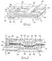
- FIG. 1 shows a portion of a cylinder head gasket 10 of the type Multilayer.
- These sheets comprise two plates 12 and 14 lower and upper, in this case plates each provided with a rib 16 and 18.
- a stopper 22 On the side of the cylinder hole 20, there is provided a stopper 22, peripheral, interposed between the two lower and upper plates.
- This stopper is made in one piece 24, coming from casting or machining.
- This stopper 22 is provided with a housing 28. This accommodation is obtained by any medium, such as casting, stamping, machining, stamping.
- the total height leads to a thickness E.
- a sensor 30 is disposed in this housing, resting or secured to the plate lower.
- the housing 28 is advantageously open on the cylinder hole 20 by one 32 of its sides, opening into the combustion chamber.
- the senor can be in direct contact with the atmosphere prevailing in said room, which allows measurements of different parameters according to the nature of the sensor.
- the housing 28 also has a passage 34 of son 36, vis-à-vis the 32 open side.
- These wires 36 are connected to the sensor 30. They comprise an extension possibly in a flat cladding 38, for example molded having a section in double baffles. This section can also be defined by a U with 40 branches open and 42 flat bottom.
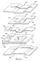
- the minimum configuration cylinder head gasket as described further comprises a base plate 44, plate to which is joined the stopper, mounted floating in this first embodiment.
- This base plate has a window 46 to the right of the son 36 of the sensor 30 and in alignment with the housing 28.
- This window is of suitable dimensions to receive the double baffle of the branches 40 and the bottom 42.
- the thickness e1 of the base plate is greater than the thickness of the wires 36, including in their cladding 38.
- interlay plate comprises a bridge 50 and two windows 52, 54 open, disposed on either side of this bridge.
- Both windows are oriented to come over the sensor wires 36 and more particularly of its cladding 38.
- the bridging is arranged to be positioned above the flat bottom 42, allowing the two branches 40 to pass on both sides.
- the thickness e2 of the intermediate plate is greater than the thickness of the wires 36, including in their cladding 38.
- the sum of the thickness e1 of the base plate and the thickness e2 of the intermediate plate remains less than the thickness E of the stopper.
- the son 36 and their possible sheathing 38 pass through the double baffled channel resulting from the geometries of the different parts constituting the cylinder head gasket.
- the stopper takes up the clamping forces between the motor unit BM and the breech CU .
- the bottom plate 12 and upper 14 seal the right of the stopper in the sensor area.
- a filling material is preferably attached to the sensor 30, in the housing 28 on the one hand to immobilize it and on the other hand to ensure the first sealing barrier in the most efficient manner.
- the second sealing barrier it is also realized in the right ribs.
- the rib 16 of the lower plate 12 comes under pressure on the base plate 44 and the rib 18 comes under pressure on the upper plate 14.
- FIGS. 4, 5 and 6 show a variant in which the elements identical and having the same functions bear the same references increased by 100.
- the base plate 144 is a thick plate with the stopper 122 integrated, that is to say leading to a monolithic assembly.
- This base plate comprises a window 146 substantially identical to the window 46 except that the support edges of the wires 136 with a sheath 138 on the window are chamfered.
- the intermediate plate 154 is of the thin plate type so that all the thicknesses is less than the thickness to the right of the stopper, as previously. Its thickness is substantially that of the threads 136.
- This plate comprises the right of the double chicane, the right of the flat bottom 142, a bridging 150, projecting, which is in profile substantially conjugated with that of the window 146 of the base plate.
- the assembly is identical to the previous one, it is advisable to adapt the profile of ribs 116 and 118 so that the pressure forces exert well on both lower and upper plates.
- Seals are respected and the seal can fulfill its function first between the engine block and the cylinder head.
- the object of the present invention is achieved since the wires emerge from the cylinder head gasket in the thickness of which they are embedded, transmitting the sensor information to a central datalogger and processing, this without ever being subject to compression to generate degradations.
- the radius of curvature at the right of the baffle is compatible with the allowed bending radii, without disturbing the information circulating there.
- the edges of the different windows and housing may be chamfered or radiated as required.
Landscapes
- Engineering & Computer Science (AREA)
- General Engineering & Computer Science (AREA)
- Mechanical Engineering (AREA)
- Gasket Seals (AREA)
- Cylinder Crankcases Of Internal Combustion Engines (AREA)
- Combined Controls Of Internal Combustion Engines (AREA)
- Measuring Fluid Pressure (AREA)
- Investigating Or Analyzing Materials By The Use Of Electric Means (AREA)
Claims (9)
- Anordnung einer mehrlagigen Zylinderkopfdichtung (10) mit mindestens zwei mit Rippen (16, 18; 116, 118) versehenen Platten, einer unteren und einer oberen (12, 14; 112, 114), mit einer Basisplatte (44; 144) und mit einer Zwischenplatte (48; 148), mit einem Sensor (30, 130), der in direkter Nähe des Zylinderlochrands (20, 120) angeordnet ist, und mit Drähten (36, 136) zur Übertragung der von diesem Sensor kommenden Informationen, dadurch gekennzeichnet, dass sie darin besteht, zwischen der Basisplatte und der Zwischenplatte eine Umlenkplatte (46, 52, 54; 146, 152, 154) für den Durchgang der Drähte (36; 136) entlang dieser Umlenkplatte auszubilden.
- Anordnung einer mehrlagigen Zylinderkopfdichtung (10) nach Anspruch 1, dadurch gekennzeichnet, dass die Basisplatte (44; 144) ein Fenster (46; 146) vor den Drähten (36; 136) des Sensors (30; 130) und die Zwischenplatte (48; 148) eine Brücke (50; 150) und zwei offene Fenster (52, 54; 152, 154) aufweist, die zu beiden Seiten dieser Brücke angeordnet sind.
- Anordnung einer mehrlagigen Zylinderkopfdichtung (10) nach Anspruch 2, dadurch gekennzeichnet, dass die Brücke (50; 150) ausgebildet ist, um sich über den Drähten zu positionieren, die umgelenkt. mit einem flachen Boden (42; 142) und zwei Zweigen (40; 140) durchlaufen.
- Anordnung einer mehrlagigen Zylinderkopfdichtung (10) nach Anspruch 3, dadurch gekennzeichnet, dass die Zwischenplatte (48) eine Dicke hat, die größer ist als diejenige der Drähte, und dass die Brücke (50) sich in der Ebene dieser Zwischenplatte befindet (48).
- Anordnung einer mehrlagigen Zylinderkopfdichtung (10) nach Anspruch 3, dadurch gekennzeichnet, dass die Zwischenplatte (148) eine Dicke im Wesentlichen gleich derjenigen der Drähte hat, und dass die Brücke (150) in das Fenster (146) der Basisplatte (144) vorsteht.
- Anordnung einer mehrlagigen Zylinderkopfdichtung (10) nach einem der vorhergehenden Ansprüche, dadurch gekennzeichnet, dass sie einen Stopper (22, 122) aufweist, der zwischen den gerippten Platten (12, 14; 112, 114) und vor der Basisplatte (44; 144) und der Zwischenplatte (48, 148) angeordnet ist, wobei die Höhe E dieses Stoppers größer ist als die Summe der Höhen e1 der Basisplatte und e2 der Zwischenplatte.
- Anordnung einer mehrlagigen Zylinderkopfdichtung (10) nach Anspruch 6, dadurch gekennzeichnet, dass der Stopper (22, 122) einen Sitz (28, 128) zur Aufnahme des Sensors (30, 130) aufweist, wobei der Sitz auf einer Seite (32, 132) zum Zylinderloch (20, 120) hin offen ist und einen Durchgang (34, 134) aufweist.
- Anordnung einer mehrlagigen Zylinderkopfdichtung (10) nach Anspruch 7, dadurch gekennzeichnet, dass die Freiräume im Sitz (28, 128) um den Sensor herum gefüllt sind.
- Anordnung einer mehrlagigen Zylinderkopfdichtung (10) nach einem der Ansprüche 6, 7 oder 8, dadurch gekennzeichnet, dass der Stopper (22, 122) bezüglich der Platten schwimmend angeordnet ist.
Applications Claiming Priority (3)
| Application Number | Priority Date | Filing Date | Title |
|---|---|---|---|
| FR0208527 | 2002-07-08 | ||
| FR0208527A FR2841938B1 (fr) | 2002-07-08 | 2002-07-08 | Agencement d'un capteur et de ses connexions filaires dans un joint de culasse metallique, multifeuilles |
| PCT/EP2003/006922 WO2004005772A1 (fr) | 2002-07-08 | 2003-06-30 | Agencement d'un capteur et de ses connexions filaires dans un joint de culasse metallique, multifeuilles |
Publications (2)
| Publication Number | Publication Date |
|---|---|
| EP1520128A1 EP1520128A1 (de) | 2005-04-06 |
| EP1520128B1 true EP1520128B1 (de) | 2005-12-21 |
Family
ID=29725246
Family Applications (1)
| Application Number | Title | Priority Date | Filing Date |
|---|---|---|---|
| EP03762555A Expired - Lifetime EP1520128B1 (de) | 2002-07-08 | 2003-06-30 | Anordnung für einen sensor und seine drahtverbindungen in einer mehrplatten-zylinderkopfdichtung aus metall |
Country Status (9)
| Country | Link |
|---|---|
| US (1) | US20060055117A1 (de) |
| EP (1) | EP1520128B1 (de) |
| JP (1) | JP4178147B2 (de) |
| CN (1) | CN100383437C (de) |
| AT (1) | ATE313745T1 (de) |
| AU (1) | AU2003252533A1 (de) |
| DE (1) | DE60302899T2 (de) |
| FR (1) | FR2841938B1 (de) |
| WO (1) | WO2004005772A1 (de) |
Families Citing this family (3)
| Publication number | Priority date | Publication date | Assignee | Title |
|---|---|---|---|---|
| US4874802A (en) * | 1988-06-16 | 1989-10-17 | Mobay Corporation | Polycarbonate compositions resistant to gamma radiation |
| JP2005090722A (ja) * | 2003-09-19 | 2005-04-07 | Uchiyama Mfg Corp | 多機能ガスケット |
| EP2438330A2 (de) * | 2009-06-01 | 2012-04-11 | Federal-Mogul Corporation | Kompressionssensordichtungsbaugruppe und konstruktionsverfahren dafür |
Family Cites Families (12)
| Publication number | Priority date | Publication date | Assignee | Title |
|---|---|---|---|---|
| FR2465077A1 (fr) * | 1979-09-14 | 1981-03-20 | Thomson Csf | Dispositif d'insertion d'un senseur dans les conduits d'echappement d'un moteur a combustion interne et systeme regulateur du dosage de carburant mettant en oeuvre un tel dispositif |
| US5195365A (en) * | 1990-08-24 | 1993-03-23 | Toyota Jidosha Kabushiki Kaisha | Device for detecting combustion pressure of an internal combustion engine |
| US5659132A (en) | 1995-03-07 | 1997-08-19 | Fel-Pro Incorporated | Gasket enclosed sensor system |
| JPH09195814A (ja) | 1996-01-18 | 1997-07-29 | Nippon Reinz Co Ltd | センサ付シリンダヘッドガスケット |
| JPH1194676A (ja) * | 1997-09-17 | 1999-04-09 | Hitachi Ltd | 筒内圧センサ |
| CN1147721C (zh) * | 1999-03-19 | 2004-04-28 | 中国船舶工业总公司第七研究院第七一一研究所 | 气体发动机气缸不正常燃烧现象的检测方法及报警装置 |
| CN2485639Y (zh) * | 2000-07-28 | 2002-04-10 | 武汉理工大学 | 发动机气缸套内壁温度测量传感器 |
| JP2002276809A (ja) * | 2001-03-15 | 2002-09-25 | Taiho Kogyo Co Ltd | シリンダヘッドガスケット |
| WO2003071119A2 (en) * | 2002-02-15 | 2003-08-28 | Dana Corporation | Apparatus for measuring pressures in engine cylinders |
| CA2476095A1 (en) * | 2002-02-15 | 2003-08-28 | Dana Corporation | Multiple-layer cylinder head gasket with integral pressure sensor apparatus for measuring pressures within engine cylinders |
| US6701775B1 (en) * | 2002-02-15 | 2004-03-09 | Dana Corporation | Pressure sensor apparatus for measuring pressures including knock conditions in engine cylinders |
| US6739183B1 (en) * | 2002-02-15 | 2004-05-25 | Dana Corporation | Multiple-layer cylinder head gasket with integral pressure sensor apparatus for measuring pressures within engine cylinders |
-
2002
- 2002-07-08 FR FR0208527A patent/FR2841938B1/fr not_active Expired - Fee Related
-
2003
- 2003-06-30 CN CNB038161095A patent/CN100383437C/zh not_active Expired - Fee Related
- 2003-06-30 US US10/520,443 patent/US20060055117A1/en not_active Abandoned
- 2003-06-30 JP JP2004518632A patent/JP4178147B2/ja not_active Expired - Fee Related
- 2003-06-30 WO PCT/EP2003/006922 patent/WO2004005772A1/fr not_active Ceased
- 2003-06-30 DE DE60302899T patent/DE60302899T2/de not_active Expired - Lifetime
- 2003-06-30 AU AU2003252533A patent/AU2003252533A1/en not_active Abandoned
- 2003-06-30 AT AT03762555T patent/ATE313745T1/de not_active IP Right Cessation
- 2003-06-30 EP EP03762555A patent/EP1520128B1/de not_active Expired - Lifetime
Also Published As
| Publication number | Publication date |
|---|---|
| ATE313745T1 (de) | 2006-01-15 |
| AU2003252533A1 (en) | 2004-01-23 |
| DE60302899T2 (de) | 2006-08-03 |
| EP1520128A1 (de) | 2005-04-06 |
| US20060055117A1 (en) | 2006-03-16 |
| DE60302899D1 (de) | 2006-01-26 |
| CN100383437C (zh) | 2008-04-23 |
| JP4178147B2 (ja) | 2008-11-12 |
| CN1666047A (zh) | 2005-09-07 |
| FR2841938B1 (fr) | 2004-08-27 |
| JP2006507438A (ja) | 2006-03-02 |
| WO2004005772A1 (fr) | 2004-01-15 |
| FR2841938A1 (fr) | 2004-01-09 |
Similar Documents
| Publication | Publication Date | Title |
|---|---|---|
| FR2866431A1 (fr) | Detecteur de gaz comportant une entree de gaz concue pour creer un ecoulement de gaz desire | |
| FR2816003A1 (fr) | Collecteur d'echappement isole par une fente d'air pour un moteur a combustion interne | |
| FR2566469A1 (fr) | Pompe a fluide et dispositif de lubrification sous pression pour compresseur de refrigeration | |
| EP1520128B1 (de) | Anordnung für einen sensor und seine drahtverbindungen in einer mehrplatten-zylinderkopfdichtung aus metall | |
| EP3417157A1 (de) | Schmierdüse mit vereinfachter herstellung | |
| EP0095989A1 (de) | Fluidabdichtungssystem für Zylinderkopfdichtung einer Brennkraftmaschine | |
| FR2831210A1 (fr) | Systeme de surveillance et commande de combustion de moteur avec un capteur de combustion de joint de culasse integre | |
| EP0753689A1 (de) | Abdichtung für Verbrennungskraftmaschinen, insbesondere Zylinderkopfdichtung | |
| EP2748457B1 (de) | Piezoelektrische zündvorrichtung und entsprechendes verfahren für eine turbomaschinenbrennkammer | |
| EP0576316B1 (de) | Flexibele Dichtung mit Ummantelung | |
| FR2849198A1 (fr) | Detecteur de gaz possedant une structure amelioree pour l'installation d'un capot de protection | |
| FR2849199A1 (fr) | Detecteur de gaz possedant une struture perfectionnee pour reduire l'endommagement thermique d'un joint d'etancheite hermetique | |
| EP1409898B1 (de) | Zylinderkopfdichtung mit einem kante-zu-kante-anschlagsring | |
| EP0391014B1 (de) | Absorptions-Schalldämpfer für Brennkraftmaschinen, insbesondere für Geländefahrzeuge | |
| EP4211504B1 (de) | Dichtung für eine kabelspleissbox | |
| EP1905971A2 (de) | Vorrichtung zur Trennung bestimmter Stoffe, die von einem Verbrennungsmotor produziert werden | |
| EP1469207A1 (de) | Kupplungsvorrichtung durch Einführen zwischen zwei Elementen | |
| EP0508891B1 (de) | Verfahren zur Herstellung einer Vorrichtung zur Kontrolle der Ansaugluft eines Kraftfahrzeuges mit einem Thermistor zur Messung der Temperatur der Ansaugluft und nach diesem Verfahren hergestellte Vorrichtung | |
| EP3645906B1 (de) | Hydraulikpumpe für eine hydraulische verbindungsstelle eines kupplungsmechanismus | |
| EP0537051A1 (de) | Anlage zum Pumpen von Gasen mit Pumpengeschwindigkeitsregelung | |
| FR2739668A1 (fr) | Dispositif perfectionne d'obturation a guide centreur lubrifie pour tube d'amortisseur hydraulique pressurise | |
| EP3109517B1 (de) | Befestigungsvorrichtung mindestens eines kabelbündels auf einem gehäuse | |
| EP3109518B1 (de) | Montage von dichtungsfuge und gehäuse mit spannvorrichtung für kabelbündel | |
| FR2783915A1 (fr) | Transducteur ultrasonore | |
| EP0092469B1 (de) | Entlüftungsvorrichtung für Zylinder-Kolbenanordnung und Radbremszylinder mit solcher Vorrichtung |
Legal Events
| Date | Code | Title | Description |
|---|---|---|---|
| PUAI | Public reference made under article 153(3) epc to a published international application that has entered the european phase |
Free format text: ORIGINAL CODE: 0009012 |
|
| 17P | Request for examination filed |
Effective date: 20041217 |
|
| AK | Designated contracting states |
Kind code of ref document: A1 Designated state(s): AT BE BG CH CY CZ DE DK EE ES FI FR GB GR HU IE IT LI LU MC NL PT RO SE SI SK TR |
|
| AX | Request for extension of the european patent |
Extension state: AL LT LV MK |
|
| GRAP | Despatch of communication of intention to grant a patent |
Free format text: ORIGINAL CODE: EPIDOSNIGR1 |
|
| GRAS | Grant fee paid |
Free format text: ORIGINAL CODE: EPIDOSNIGR3 |
|
| GRAA | (expected) grant |
Free format text: ORIGINAL CODE: 0009210 |
|
| AK | Designated contracting states |
Kind code of ref document: B1 Designated state(s): AT BE BG CH CY CZ DE DK EE ES FI FR GB GR HU IE IT LI LU MC NL PT RO SE SI SK TR |
|
| PG25 | Lapsed in a contracting state [announced via postgrant information from national office to epo] |
Ref country code: AT Free format text: LAPSE BECAUSE OF FAILURE TO SUBMIT A TRANSLATION OF THE DESCRIPTION OR TO PAY THE FEE WITHIN THE PRESCRIBED TIME-LIMIT Effective date: 20051221 Ref country code: SI Free format text: LAPSE BECAUSE OF FAILURE TO SUBMIT A TRANSLATION OF THE DESCRIPTION OR TO PAY THE FEE WITHIN THE PRESCRIBED TIME-LIMIT Effective date: 20051221 Ref country code: RO Free format text: LAPSE BECAUSE OF FAILURE TO SUBMIT A TRANSLATION OF THE DESCRIPTION OR TO PAY THE FEE WITHIN THE PRESCRIBED TIME-LIMIT Effective date: 20051221 Ref country code: NL Free format text: LAPSE BECAUSE OF FAILURE TO SUBMIT A TRANSLATION OF THE DESCRIPTION OR TO PAY THE FEE WITHIN THE PRESCRIBED TIME-LIMIT Effective date: 20051221 Ref country code: CZ Free format text: LAPSE BECAUSE OF FAILURE TO SUBMIT A TRANSLATION OF THE DESCRIPTION OR TO PAY THE FEE WITHIN THE PRESCRIBED TIME-LIMIT Effective date: 20051221 Ref country code: IE Free format text: LAPSE BECAUSE OF FAILURE TO SUBMIT A TRANSLATION OF THE DESCRIPTION OR TO PAY THE FEE WITHIN THE PRESCRIBED TIME-LIMIT Effective date: 20051221 Ref country code: SK Free format text: LAPSE BECAUSE OF FAILURE TO SUBMIT A TRANSLATION OF THE DESCRIPTION OR TO PAY THE FEE WITHIN THE PRESCRIBED TIME-LIMIT Effective date: 20051221 Ref country code: FI Free format text: LAPSE BECAUSE OF FAILURE TO SUBMIT A TRANSLATION OF THE DESCRIPTION OR TO PAY THE FEE WITHIN THE PRESCRIBED TIME-LIMIT Effective date: 20051221 |
|
| REG | Reference to a national code |
Ref country code: GB Ref legal event code: FG4D Free format text: NOT ENGLISH |
|
| REG | Reference to a national code |
Ref country code: CH Ref legal event code: EP |
|
| REG | Reference to a national code |
Ref country code: IE Ref legal event code: FG4D Free format text: LANGUAGE OF EP DOCUMENT: FRENCH |
|
| REF | Corresponds to: |
Ref document number: 60302899 Country of ref document: DE Date of ref document: 20060126 Kind code of ref document: P |
|
| PG25 | Lapsed in a contracting state [announced via postgrant information from national office to epo] |
Ref country code: GR Free format text: LAPSE BECAUSE OF FAILURE TO SUBMIT A TRANSLATION OF THE DESCRIPTION OR TO PAY THE FEE WITHIN THE PRESCRIBED TIME-LIMIT Effective date: 20060321 Ref country code: DK Free format text: LAPSE BECAUSE OF FAILURE TO SUBMIT A TRANSLATION OF THE DESCRIPTION OR TO PAY THE FEE WITHIN THE PRESCRIBED TIME-LIMIT Effective date: 20060321 Ref country code: BG Free format text: LAPSE BECAUSE OF FAILURE TO SUBMIT A TRANSLATION OF THE DESCRIPTION OR TO PAY THE FEE WITHIN THE PRESCRIBED TIME-LIMIT Effective date: 20060321 Ref country code: SE Free format text: LAPSE BECAUSE OF FAILURE TO SUBMIT A TRANSLATION OF THE DESCRIPTION OR TO PAY THE FEE WITHIN THE PRESCRIBED TIME-LIMIT Effective date: 20060321 |
|
| PG25 | Lapsed in a contracting state [announced via postgrant information from national office to epo] |
Ref country code: ES Free format text: LAPSE BECAUSE OF FAILURE TO SUBMIT A TRANSLATION OF THE DESCRIPTION OR TO PAY THE FEE WITHIN THE PRESCRIBED TIME-LIMIT Effective date: 20060401 |
|
| PG25 | Lapsed in a contracting state [announced via postgrant information from national office to epo] |
Ref country code: PT Free format text: LAPSE BECAUSE OF FAILURE TO SUBMIT A TRANSLATION OF THE DESCRIPTION OR TO PAY THE FEE WITHIN THE PRESCRIBED TIME-LIMIT Effective date: 20060522 |
|
| NLV1 | Nl: lapsed or annulled due to failure to fulfill the requirements of art. 29p and 29m of the patents act | ||
| PG25 | Lapsed in a contracting state [announced via postgrant information from national office to epo] |
Ref country code: HU Free format text: LAPSE BECAUSE OF FAILURE TO SUBMIT A TRANSLATION OF THE DESCRIPTION OR TO PAY THE FEE WITHIN THE PRESCRIBED TIME-LIMIT Effective date: 20060622 |
|
| GBT | Gb: translation of ep patent filed (gb section 77(6)(a)/1977) |
Effective date: 20060601 |
|
| PG25 | Lapsed in a contracting state [announced via postgrant information from national office to epo] |
Ref country code: BE Free format text: LAPSE BECAUSE OF NON-PAYMENT OF DUE FEES Effective date: 20060630 Ref country code: MC Free format text: LAPSE BECAUSE OF NON-PAYMENT OF DUE FEES Effective date: 20060630 |
|
| PGFP | Annual fee paid to national office [announced via postgrant information from national office to epo] |
Ref country code: IT Payment date: 20060630 Year of fee payment: 4 |
|
| REG | Reference to a national code |
Ref country code: IE Ref legal event code: FD4D |
|
| PLBE | No opposition filed within time limit |
Free format text: ORIGINAL CODE: 0009261 |
|
| STAA | Information on the status of an ep patent application or granted ep patent |
Free format text: STATUS: NO OPPOSITION FILED WITHIN TIME LIMIT |
|
| 26N | No opposition filed |
Effective date: 20060922 |
|
| BERE | Be: lapsed |
Owner name: CARL FREUDENBERG Effective date: 20060630 |
|
| REG | Reference to a national code |
Ref country code: CH Ref legal event code: PL |
|
| GBPC | Gb: european patent ceased through non-payment of renewal fee |
Effective date: 20070630 |
|
| PG25 | Lapsed in a contracting state [announced via postgrant information from national office to epo] |
Ref country code: LI Free format text: LAPSE BECAUSE OF NON-PAYMENT OF DUE FEES Effective date: 20070630 Ref country code: CH Free format text: LAPSE BECAUSE OF NON-PAYMENT OF DUE FEES Effective date: 20070630 |
|
| PG25 | Lapsed in a contracting state [announced via postgrant information from national office to epo] |
Ref country code: GB Free format text: LAPSE BECAUSE OF NON-PAYMENT OF DUE FEES Effective date: 20070630 |
|
| PG25 | Lapsed in a contracting state [announced via postgrant information from national office to epo] |
Ref country code: EE Free format text: LAPSE BECAUSE OF FAILURE TO SUBMIT A TRANSLATION OF THE DESCRIPTION OR TO PAY THE FEE WITHIN THE PRESCRIBED TIME-LIMIT Effective date: 20051221 |
|
| PG25 | Lapsed in a contracting state [announced via postgrant information from national office to epo] |
Ref country code: TR Free format text: LAPSE BECAUSE OF FAILURE TO SUBMIT A TRANSLATION OF THE DESCRIPTION OR TO PAY THE FEE WITHIN THE PRESCRIBED TIME-LIMIT Effective date: 20051221 Ref country code: LU Free format text: LAPSE BECAUSE OF NON-PAYMENT OF DUE FEES Effective date: 20060630 |
|
| PG25 | Lapsed in a contracting state [announced via postgrant information from national office to epo] |
Ref country code: CY Free format text: LAPSE BECAUSE OF FAILURE TO SUBMIT A TRANSLATION OF THE DESCRIPTION OR TO PAY THE FEE WITHIN THE PRESCRIBED TIME-LIMIT Effective date: 20051221 |
|
| PG25 | Lapsed in a contracting state [announced via postgrant information from national office to epo] |
Ref country code: IT Free format text: LAPSE BECAUSE OF NON-PAYMENT OF DUE FEES Effective date: 20070630 |
|
| PGFP | Annual fee paid to national office [announced via postgrant information from national office to epo] |
Ref country code: FR Payment date: 20100630 Year of fee payment: 8 |
|
| REG | Reference to a national code |
Ref country code: DE Ref legal event code: R081 Ref document number: 60302899 Country of ref document: DE Owner name: ELRINGKLINGER AG, DE Free format text: FORMER OWNER: CARL FREUDENBERG, 69469 WEINHEIM, DE Effective date: 20110824 |
|
| REG | Reference to a national code |
Ref country code: FR Ref legal event code: ST Effective date: 20120229 |
|
| PG25 | Lapsed in a contracting state [announced via postgrant information from national office to epo] |
Ref country code: FR Free format text: LAPSE BECAUSE OF NON-PAYMENT OF DUE FEES Effective date: 20110630 |
|
| PGFP | Annual fee paid to national office [announced via postgrant information from national office to epo] |
Ref country code: DE Payment date: 20130621 Year of fee payment: 11 |
|
| REG | Reference to a national code |
Ref country code: DE Ref legal event code: R119 Ref document number: 60302899 Country of ref document: DE |
|
| REG | Reference to a national code |
Ref country code: DE Ref legal event code: R119 Ref document number: 60302899 Country of ref document: DE Effective date: 20150101 |
|
| PG25 | Lapsed in a contracting state [announced via postgrant information from national office to epo] |
Ref country code: DE Free format text: LAPSE BECAUSE OF NON-PAYMENT OF DUE FEES Effective date: 20150101 |