EP1520165B1 - Procede et dispositif de spectrometrie d'emission - Google Patents
Procede et dispositif de spectrometrie d'emission Download PDFInfo
- Publication number
- EP1520165B1 EP1520165B1 EP03761506A EP03761506A EP1520165B1 EP 1520165 B1 EP1520165 B1 EP 1520165B1 EP 03761506 A EP03761506 A EP 03761506A EP 03761506 A EP03761506 A EP 03761506A EP 1520165 B1 EP1520165 B1 EP 1520165B1
- Authority
- EP
- European Patent Office
- Prior art keywords
- laser
- pulse
- plasma
- laser beam
- measuring
- Prior art date
- Legal status (The legal status is an assumption and is not a legal conclusion. Google has not performed a legal analysis and makes no representation as to the accuracy of the status listed.)
- Expired - Lifetime
Links
Images


Classifications
-
- G—PHYSICS
- G01—MEASURING; TESTING
- G01J—MEASUREMENT OF INTENSITY, VELOCITY, SPECTRAL CONTENT, POLARISATION, PHASE OR PULSE CHARACTERISTICS OF INFRARED, VISIBLE OR ULTRAVIOLET LIGHT; COLORIMETRY; RADIATION PYROMETRY
- G01J3/00—Spectrometry; Spectrophotometry; Monochromators; Measuring colours
- G01J3/28—Investigating the spectrum
- G01J3/443—Emission spectrometry
-
- G—PHYSICS
- G01—MEASURING; TESTING
- G01N—INVESTIGATING OR ANALYSING MATERIALS BY DETERMINING THEIR CHEMICAL OR PHYSICAL PROPERTIES
- G01N21/00—Investigating or analysing materials by the use of optical means, i.e. using sub-millimetre waves, infrared, visible or ultraviolet light
- G01N21/62—Systems in which the material investigated is excited whereby it emits light or causes a change in wavelength of the incident light
- G01N21/71—Systems in which the material investigated is excited whereby it emits light or causes a change in wavelength of the incident light thermally excited
- G01N21/718—Laser microanalysis, i.e. with formation of sample plasma
Definitions
- the invention relates to a method and a device for the quantitative and qualitative multi-element analysis of moving objects with the emission spectrometry, preferably the laser emission spectrometry.
- the concentration of individual chemical elements in a sample is determined by using a focused laser beam to generate a plasma on the surface of the measurement object and the concentration of the considered element in the sample using the element-specific emissions of the laser-induced plasma is determined.
- Focusing optics 1 focuses a pulsed laser beam 2 with the propagation direction 3 onto a surface element 4 of the measurement object.
- the coordinate system is chosen so that the propagation direction 3 of the laser beam 2 runs antiparallel to the z-axis.
- the normal 5 of the surface element 4 encloses an angle ⁇ with the z-axis or the laser beam axis.
- the piercing point 6 of the propagation direction 3 with the surface element 4 is the center of the projection 7 of the laser beam cross section on the surface element 4.
- the distance of the focal plane 8 of the laser beam 2 from the puncture point 6 is denoted by ⁇ s.
- the focal plane 8 lies behind the puncture point 6, as seen from the focusing optics, this corresponds to positive values for ⁇ s.
- ⁇ s is chosen to be positive.
- the distance of the focusing optics 1 from the puncture point 6 will be denoted by d.
- the emission of the resulting laser-induced plasma at location 6 is collected by the receiving optics of the detector unit 9 and guided into a spectrometer.
- the detector unit of the spectrometer determines the time-integrated emission of the observed spectral lines for a defined time window.
- concentration of the analyte in the sample is then determined with the aid of a calibration function from the temporally integrated emissions of the considered spectral lines in sections.
- the laser emission spectrometry can be operated either with fixed or with variable focal length of the focusing optics.
- the measured object In the case of laser emission spectrometry with focusing optics, the measured object must be precisely positioned to a few millimeters in order to obtain a quantitative statement about analyte concentrations in the material of the test object by means of a previously created calibration.
- the detected solid angle of the plasma emission changes due to the changed distance of the sample surface to the fixed position of the receiving optics of the detector unit 9 or by a partial shading of the laser-induced plasma by the measurement object.
- This change can be compensated in part by evaluating the ratio of the measurement signal of the emission line under consideration to a combination of other line emission signals and a signal proportional to the total emission of the considered plasma. This method is called "referencing" or "internal standardization".
- Another systematic error also results from a changed characteristic of the emission of the laser-induced plasma.
- a quantitative statement about analyte concentrations in the material of the measurement object is made difficult or impossible or the measured analyte concentration is subject to errors.
- the invention is based on the technical problem of providing a method and an apparatus for emission spectrometry, in particular laser emission spectrometry, with improved measuring accuracy, in particular for the emission spectrometric detection of moving objects.
- the proposed solution is based on the knowledge that, according to the state of the art, measuring locations on the measuring object are always detected whose surface is geometrically unsuitable for a quantitative measurement.
- a measurement that is as accurate as possible assumes that the geometric condition of the measuring location is largely identical to that which existed when the calibration curve was recorded. If the calibration curve was measured with geometry parameters P1, P2 .. PN, then it only fulfills its nominal function of the calibration exactly, if - with otherwise fixed parameters, such as the Laser parameters - the same geometry parameters are available when measuring a DUT.
- a tolerance range [T1 .. T2] for the geometry parameters P1, P2 .. PN is given, which in each case the geometry parameters present in the calibration measurement as well as possible represent.
- the given geometry parameters with respect to type and tolerance range should correspond to those geometry parameters at which the calibration curve was recorded.
- the width of the tolerance range of the geometry parameters results from the requirements of the application to the accuracy of the concentration determination and from the restriction by the components used.
- the same geometry parameters P1, P2 .. PN are measured at potential measuring locations of the workpiece.
- the distance d of the autofocusing optics to the workpiece surface is in any case continuously determined as a geometry parameter.
- elemental analysis is therefore carried out only for those potential measuring locations in which at least one of the additional geometry parameters is within a predetermined tolerance range [T1 .. T2].
- one of the geometry parameters is the distance d between the focusing optics and the workpiece surface.
- this distance d should also lie within a tolerance range defined by the calibration measurement, wherein it should be emphasized that the tolerance range for the parameter d is independent of the range within which the autofocus device is still reliable.
- the inclination ⁇ of the workpiece surface present at the potential measuring location is determined with respect to the laser beam axis.
- d and ⁇ should be within a tolerance range: d u ⁇ d ⁇ d O - ⁇ Max ⁇ ⁇ ⁇ ⁇ Max
- these parameters define a process window with regard to the geometry parameters within which emission spectrometry is operated.
- this procedure can also be generalized to more relevant geometry parameters.
- the surface profile is determined by means of a triangulation method before the plasma induction of at least a partial area of the workpiece surface, and the additional geometry parameters are calculated from the surface profile.
- a comparison is made with the predetermined setpoint values or it is checked whether at least one geometry parameter of the measurement location falls within the predetermined tolerance range. The accuracy of the measurement result is increasingly increased, if all geometry parameters are within the tolerance range.
- means are provided for measuring the sample surface which also measure transversely to the direction of movement of the test object.
- the distance d between the surface element 4 and the focusing optics 1 can be determined with the aid of a triangulation unit 17, see Fig. 4a , The arrangement of the surface points 15 of the measurement object detected in this way is shown in FIG Fig. 4b shown schematically.
- a triangulation unit 17 measures the vertical distances s1, s2, s3 etc. from a reference plane to discrete measuring points 15 which are located on the surface of the test object at the same time or in chronological succession.
- the triangulation unit can be realized for example by a laser-based light-section sensor, a multi-point tri-angulation unit or multiple triangulation sensors.
- the distance DT of the lines 14 and 14 'from one another is determined by the measuring rate of the triangulation unit and the speed of the surface of the measuring object 4'.
- the course of the sample surface 4 'between the detected triangulation measurement points 15 is determined by interpolation.
- the method of the invention can profitably be used in the examination of moving objects.
- a measurement of parts can be made on a belt passing the analysis laser, such as aluminum or electronic scrap parts.
- the measuring operation takes place in such a way that an element analysis is carried out only for those potential measuring locations in which at least one of the additional geometry parameters is within a predetermined tolerance range [T1 .. T2] is located.
- a predetermined tolerance range [T1 .. T2]
- either the data from inappropriate measurement locations can be discarded, or else a plasma is induced only at the locations at which the predetermined geometry parameters are within the tolerance range.
- only a pump pulse, but not a laser pulse is favorably triggered in the event that there is no suitable measuring location. The thermal stability of the laser is thereby increased.
- the laser beam is deflected transversely to the direction of movement of the measurement object. In this way not only potential measuring locations in the feed direction of the analysis laser can be selected, but also measuring locations perpendicular to this feed direction. This increases the number of usable measurement points on the surface of the DUT, thus increasing the accuracy and reliability of the analysis and identification.
- the laser beam is applied with variable pulse spacing ⁇ T.
- the pulse spacing can initially be selected such that the pulse spacing is reduced for a larger relative speed between the analysis laser and the measurement object, and increased for a smaller relative speed.
- the pulse interval can be selected smaller in order to increase the probability of being able to carry out a measurement. The greater number of measurements made possible thereby improves the statistical accuracy of the analysis result.
- a pulse interval is selected whose value is within a predetermined tolerance range [ ⁇ T min ... ⁇ T max ]. This increases the reliability and stability of the system.
- the time interval between two laser pulses is designated ⁇ T and is typically constant. However, it can be varied in a laser system in a limited range. Possible restrictions for the pulse interval to be set and thus the instantaneous repetition rate of the analysis laser can be, for example, an increased scattering of the pulse energy, a change in the thermal stability of the analysis laser and consequent changes in the beam profile or the beam direction, or an exceedance of the limits of the pump electronics for the generation of pump pulses be the laser medium.
- the pulse variation is advantageously carried out such that in the event that a suitable detection device such as a light barrier, a triangulation unit or the like detects a measurement object, a smaller pulse distance is selected for the analysis laser than for the case that no measurement object is detected.
- a suitable detection device such as a light barrier, a triangulation unit or the like detects a measurement object
- This procedure means that as many measurements as possible are made in the presence of a measurement object, which increases the statistical measurement accuracy. Captures the
- the analysis laser is not a measurement object so the pulse distance is increased, which allows the laser to thermalize.
- a suitable measuring position is a measuring position whose predetermined geometry parameters lie within the process window selected by the user. It is therefore optimal initially if, in the first case, ⁇ T min is selected as the pulse interval and ⁇ T max is selected in the second case.
- the pulse interval is adjusted to the nominal value ⁇ T soll of the laser system using known control methods.
- the target value .DELTA.T to the pulse interval which is specified for operation at a fixed repetition rate.
- the pulse interval is selected individually for each pulse.
- the pulse interval is always set within a system- and application-specific range [ ⁇ T min, ⁇ T max ], which also depends on the pulse intervals of the previously emitted pulses. For each individual pulse interval ⁇ T, the possible extreme values ⁇ T min and ⁇ T max are newly determined, or the pulse interval ⁇ T is set individually for each pulse.
- the device-dependent extreme values ⁇ T g min and ⁇ T g max for a single pulse interval ⁇ T and the mean pulse interval ⁇ T middle, N enter over the last N generated laser pulses.
- the pulse intervals .DELTA.T of the laser pulses are always selected so that the average pulse interval .DELTA.T means, N over the last N pulses always takes a value within the range [.DELTA.T average, N min , .DELTA.T medium, N max ].
- this can be described by the following expressions: .DELTA.T ⁇ .DELTA.T min . .DELTA.T Max .DELTA.T medium . N ⁇ .DELTA.T medium .
- Fig. 2 shown raster of possible measuring ranges 10 and 10 'on the sample surface 4'.
- Fig. 3 shows by way of example the measuring range 10 'in the yz plane in a rectangular shape.
- the height of the measuring region 10 'in the z-direction is denoted by MZ and is given by the minimum and maximum adjustable distances d u , and d o of the puncture point 6 to the focusing optics 1.
- the width MY of the measuring region 10 ' is determined by the beam deflection angle ⁇ , which is the maximum that can be set with the focusing optics, and the minimum adjustable distance d u , as the boundary of the vertical focusing region MZ.
- the width MY is chosen so that for each y-coordinate within MY within the maximum beam deflection angle ⁇ each vertical position z can be achieved within the focusing range MZ.
- the process window is thus defined as d u ⁇ d ⁇ d O - ⁇ Max ⁇ ⁇ ⁇ Max y u ⁇ y ⁇ y O .DELTA.T min ⁇ .DELTA.T ⁇ .DELTA.T Max
- the time of generation of the laser pulse is determined by the system controller and the beam of the analyzing laser is deflected transversely to the feed direction by a beam deflection unit. in y-direction - positioned.
- the surface 4 'of the measuring object 16 is detected by the triangulation unit 17 at the time t A.
- the distance values s of the triangulation measurement points 15 are transmitted to the autofocus control 18.
- the autofocus control determines in the next valid measuring range 10 'with the aid of the interpolated surface curve the next possible measuring point 12', whose parameters ⁇ T, d and ⁇ . lie in the valid process window.
- a measurement position 12' with a valid process window is preferred from small to large ⁇ T and thereby searched for each ⁇ T from small to large distances to the y-coordinate of the measuring position 12 of the preceding measuring range 10.
- measuring points are preferred which have a minimum spatial distance to the previous pulse within the scope of the possible measuring range 10 '.
- the maximum possible number of measuring points 12, 12 'on the sample surface 4' is always realized in the context of the application.
- a pump pulse of the laser is triggered, but no laser pulse.
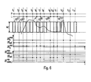
- Fig. 6 shows the described control of the pulse intervals for the measurement on a measurement object by way of example in the xz-plane.
- the x-axis is represented by an equivalent time axis (t-axis).
- the designation P stands for a triggered pump pulse, L for a triggered laser pulse.
- P stands for a triggered pump pulse
- L for a triggered laser pulse.
- Pump pulses P but no laser pulses L are triggered.
- the measurement object is in position, the surface lies in the measurement areas 10 3 ', 10 4 ' and both pulse intervals are selected to ⁇ T g min . This should allow as many successive measurements as possible.
- a suitable measuring position is found and a pump pulse and a laser pulse are triggered with a pulse interval of ⁇ T g max .
- no position can be found in the measuring range 10 12 'whose parameters lie in the process window.
- the angle ⁇ of the surface normal is too large or the surface elements are outside the vertical measuring range MZ.
- the mean pulse duration ⁇ T is medium, 3 ⁇ T set , the pulse interval is set to ⁇ T g max .
- the measurement object is no longer at the measurement position and the pulse intervals are again adjusted to ⁇ T soll .
- the parameters ⁇ T, y and d are used at time t B of the arrival of the measuring object 16 at the measuring position x B for focusing the laser beam 2 by the focusing optical system 1 onto the surface 4' of the measuring object 16.
- the focusing optics consisting from the autofocus optics 1a and the beam deflection unit 1b, focuses the laser beam 2 of the analysis laser 19 at the measurement position x B on the sample surface 4 ', see Fig. 5 ,
- the vertical distance d is adjusted by the autofocus optics 1a.
- the adjustable vertical measuring range is MZ.
- the manipulated variable of the autofocus optics is chosen so that ⁇ s is constant over all measurements.
- the y-coordinate of the next measurement position 12 ' is adjusted by the beam deflection unit 1b.
- the adjustable range for this horizontal offset is MY.
- the x-coordinate of the next measurement position 12 ' is set by the time of the measurement.
- the length of the adjustable measuring range 10 ' is MX.
- the autofocus optics 1a can be realized, for example, with a double lens system consisting of a concave and a convex lens, wherein the distance of the focus position to the focusing optics 1 can be varied by moving the concave lens parallel to the optical axis.
- the deflection unit 1b can be realized for example by means of an X / Y scanner system in conjunction with an F-theta objective.
- the emission of the laser-induced plasma 6 produced at the measuring position x B is collected by the receiving optics of the detector unit 9 and fed into a spectrometer 20.
- the receiving optics of the detector unit 9 is designed so that plasma emissions can be detected in the entire measuring range MX ⁇ MY, cf. Fig. 3 , This can be achieved for example by a fiber bundle which has a line-shaped cross-section arranged parallel to the y-axis at the measuring location, the plasma emission of each possible measuring location and whose spectrometer-side end is adapted to the entrance slit of the spectrometer via the cross-sectional conversion and is mounted in front of it.
- the dispersion unit 20a of the spectrometer 20 spectrally dissects the detected plasma emission and the detector unit 20b of the spectrometer determines the time-integrated emission of the observed spectral lines for a defined time window.
- the concentration of each analyzed analyte in the sample is determined by means of a calibration function.
- the detector unit 20b calculates the referenced individual pulse signals belonging to an analyte line for each laser-induced plasma emission. These are calculated from the ratio of the corrected time-integrated emission of the analyzed analyte line to a combination of the other corrected line emissions or a measurement signal representative of the total emission of the plasma and the vertical distances s1, s2, s3 determined by the triangulation unit 17 whose time-integrated plasma emission sections occupy a value outside the respective measuring range are discarded. For each analyte line, the mean value of all the referenced single pulse signals belonging to the measurement object 16 is then formed.
- the concentration of the analyzed analyte in the sample is determined via a calibration function, in which all averaged referenced single pulse signals of the corresponding analyte lines are received.
- the weighting of the averaged referenced single pulse signals The different analyte lines in the calibration function depend on the values of the averaged referenced single pulse signals themselves.
- the analyte concentrations thus determined for each measurement object are transmitted by the detector unit 20b of the spectrometer to a system controller 21, which uses these for example for sorting the measurement objects, for the confusion check or for documentation for quality assurance.
Landscapes
- Physics & Mathematics (AREA)
- Spectroscopy & Molecular Physics (AREA)
- Health & Medical Sciences (AREA)
- General Physics & Mathematics (AREA)
- Analytical Chemistry (AREA)
- Optics & Photonics (AREA)
- Life Sciences & Earth Sciences (AREA)
- Chemical & Material Sciences (AREA)
- Plasma & Fusion (AREA)
- Biochemistry (AREA)
- General Health & Medical Sciences (AREA)
- Nuclear Medicine, Radiotherapy & Molecular Imaging (AREA)
- Immunology (AREA)
- Pathology (AREA)
- Engineering & Computer Science (AREA)
- Investigating, Analyzing Materials By Fluorescence Or Luminescence (AREA)
- Length Measuring Devices By Optical Means (AREA)
- Electrical Discharge Machining, Electrochemical Machining, And Combined Machining (AREA)
- Spinning Or Twisting Of Yarns (AREA)
Claims (15)
- Procédé de réalisation de la spectrométrie d'émission, notamment de la spectrométrie d'émission laser,
dans lequel un rayon laser pulsé est focalisé automatiquement sur une pièce à usiner, pour la génération d'un plasma induit par laser,
dans lequel le rayonnement émis par le plasma est détecté et une analyse d'élément est réalisée avec le spectre de rayonnement détecté,
caractérisé en ce que,
avant la génération du plasma, hormis l'écart d entre l'optique d'auto focalisation et la surface de la pièce à usiner, des paramètres de géométrie supplémentaires P1, P2 .. PN d'un lieu de mesure potentiel sont déterminés sur la surface de la pièce à usiner,
et une analyse des éléments n'est réalisée que pour les lieux de mesure potentiels sur lesquels au moins l'un des paramètres de géométrie supplémentaire [T1 .. T2] se trouve dans une plage de tolérances prédéfinie [T1 .. T2]. - Procédé selon la revendication 1, caractérisé en ce que
l'angle d'inclinaison α de la surface de la pièce à usiner par rapport à l'axe du rayon laser, présent sur le lieu de mesure potentiel est déterminé en tant que paramètre de géométrie. - Procédé selon la revendication 2, caractérisé en ce que
pour le cas d'une différence entre un angle d'inclinaison mesuré α et une valeur prédéfinie αk, il est procédé à une correction du spectre d'émission. - Procédé selon l'une quelconque des revendications 1 à 3, caractérisé en ce que, avant l'induction de plasma d'au moins une zone partielle de la surface de la pièce à usiner, le profil superficiel est déterminé au moyen d'un procédé de triangulation, et les paramètres de géométrie supplémentaires sont calculés à partir du profil superficiel.
- Procédé selon l'une quelconque des revendications 1 à 4, caractérisé en ce que, un plasma n'est induit que sur les lieux, sur lesquels tous les paramètres de géométrie prédéfinis se situent dans la plage de tolérances.
- Procédé selon l'une quelconque des revendications 1 à 5, caractérisé en ce que les paramètres de géométrie prédéfinis correspondent au niveau de leur type et de leur plage de tolérances aux paramètres de géométrie sur lesquels une courbe de calibrage a été précédemment relevée.
- Procédé selon l'une quelconque des revendications 1 à 6, caractérisé en ce que le rayon laser est dévié à la transversale du sens de déplacement de l'objet à mesurer.
- Procédé selon l'une quelconque des revendications 1 à 7, caractérisé en ce que des pièces déplacées sont mesurées sur une bande.
- Procédé selon l'une quelconque des revendications 1 à 8, caractérisé en ce qu'on mesure des ferrailles d'aluminium ou des déchets électriques.
- Procédé selon l'une quelconque des revendications 1 à 9, caractérisé en ce que,
l'application du rayon laser est assurée avec un intervalle d'impulsions ΔT variable, les valeurs de ΔT se situant dans une plage de tolérances prédéfinie [ΔT min... ΔTmax] et l'intervalle d'impulsions ΔTmoyen présent dans une moyenne temporaire variant d'une valeur de consigne ΔTsoll. - Procédé selon la revendication 10,
caractérisé en ce que,
dans le cas où un dispositif de détection détecte un objet à mesurer, il est choisi un intervalle d'impulsions plus petit que dans le cas où aucun objet à mesurer n'est détecté. - Procédé selon l'une quelconque des revendications 10 à 11, caractérisé en ce que,
dans le cas où un dispositif de détection ne détecte aucun objet à mesurer, c'est une impulsion de pompage, mais non pas une impulsion laser qui est déclenchée. - Procédé selon l'une quelconque des revendications 10 à 12, caractérisé en ce que,
on règle l'intervalle d'impulsions ΔT individuellement pour chaque impulsion. - Procédé selon l'une quelconque des revendications 10 à 13, caractérisé en ce que,
pour chaque impulsion, les limites de la plage de tolérances ΔTmin, respectivement ΔTmax sont individuellement déterminées. - Dispositif pour la spectrométrie d'émission, notamment pour la spectrométrie d'émission laser, avec un laser à impulsions, pour la génération d'un plasma induit au laser, sur une pièce à usiner déplacée par rapport au rayon laser, un dispositif d'auto focalisation pour le rayon laser, un détecteur pour détecter le rayonnement émis par le laser et avec un système pour la réalisation de l'analyse d'éléments,
caractérisé en ce que,
il est prévu un moyen pour mesurer le profil superficiel de l'échantillon, à la transversale du sens de déplacement de l'objet à mesurer.
Applications Claiming Priority (3)
| Application Number | Priority Date | Filing Date | Title |
|---|---|---|---|
| DE10229498 | 2002-07-01 | ||
| DE10229498A DE10229498A1 (de) | 2002-07-01 | 2002-07-01 | Verfahren und Vorrichtung zur Durchführung der Plasmaemissionsspektrometrie |
| PCT/EP2003/006705 WO2004003528A2 (fr) | 2002-07-01 | 2003-06-25 | Procede et dispositif de spectrometrie d'emission |
Publications (2)
| Publication Number | Publication Date |
|---|---|
| EP1520165A2 EP1520165A2 (fr) | 2005-04-06 |
| EP1520165B1 true EP1520165B1 (fr) | 2008-03-19 |
Family
ID=29761558
Family Applications (1)
| Application Number | Title | Priority Date | Filing Date |
|---|---|---|---|
| EP03761506A Expired - Lifetime EP1520165B1 (fr) | 2002-07-01 | 2003-06-25 | Procede et dispositif de spectrometrie d'emission |
Country Status (9)
| Country | Link |
|---|---|
| US (1) | US7372563B2 (fr) |
| EP (1) | EP1520165B1 (fr) |
| JP (1) | JP4142644B2 (fr) |
| AT (1) | ATE389874T1 (fr) |
| AU (1) | AU2003249876B2 (fr) |
| DE (2) | DE10229498A1 (fr) |
| ES (1) | ES2304145T3 (fr) |
| WO (1) | WO2004003528A2 (fr) |
| ZA (1) | ZA200410314B (fr) |
Families Citing this family (9)
| Publication number | Priority date | Publication date | Assignee | Title |
|---|---|---|---|---|
| DE102004051310B4 (de) * | 2004-10-21 | 2010-06-02 | Fraunhofer-Gesellschaft zur Förderung der angewandten Forschung e.V. | Vorrichtung und Verfahren zur Durchführung der Emissionsspektrometrie |
| DE502005001790D1 (de) | 2005-06-23 | 2007-12-06 | Trumpf Werkzeugmaschinen Gmbh | Verfahren zur bestimmung der fokuslage eines laserstrahls |
| DE102010004774A1 (de) * | 2010-01-14 | 2011-07-28 | IMM Photonics GmbH, 85716 | Verfahren und Einrichtung zum sicheren Emittieren einer Anregungsstrahlung |
| DE102010034438A1 (de) | 2010-08-16 | 2012-02-16 | AVE Österrreich GmbH | Verfahren zur Durchführung einer Laserspektroskopie, Vorrichtung zum Durchführen des Verfahrens und Sortieranlage aufweisend die Vorrichtung |
| FR2995403B1 (fr) * | 2012-09-13 | 2014-09-12 | Commissariat Energie Atomique | Procede et dispositif de mesure quantitative par libs de cibles biomoleculaires sur bio-puce |
| US11248961B2 (en) * | 2013-03-15 | 2022-02-15 | Mat International Holdings, Llc | Methods and systems for analyzing samples |
| CN105115944B (zh) * | 2015-09-07 | 2017-12-29 | 北京科技大学 | 一种用于libs物质成分检测的自动聚焦方法及系统 |
| CN109794426A (zh) * | 2017-11-16 | 2019-05-24 | 钢铁研究总院 | 基于libs技术的全自动在线航空铝分类回收系统 |
| WO2020239239A1 (fr) * | 2019-05-31 | 2020-12-03 | Dt Equipment Ehf. | Procédé non immersif et appareil pour l'analyse quantitative de métaux et d'alliages liquides |
Family Cites Families (7)
| Publication number | Priority date | Publication date | Assignee | Title |
|---|---|---|---|---|
| DE3718672A1 (de) * | 1987-06-04 | 1988-12-15 | Metallgesellschaft Ag | Verfahren zur analyse von metallteilchen |
| DE4004627C2 (de) | 1990-02-15 | 1994-03-31 | Krupp Ag Hoesch Krupp | Verfahren zur Bestimmung von Materialeigenschaften polymerer Werkstoffe und Vorrichtung zur Durchführung des Verfahrens |
| DE4128176A1 (de) | 1991-08-24 | 1993-02-25 | Blohm & Voss Int | Vorrichtung zur automatisierten sortierung von gegenstaenden |
| DE4426475C2 (de) | 1993-07-27 | 1996-01-11 | Hohla Kristian | Vorrichtung zur laserinduzierten Plasmaspektroskopie für die Materialanalyse von auf einer Transporteinheit geführten Teilen |
| DE4426490C2 (de) | 1993-07-27 | 1996-10-24 | Hohla Kristian | Verfahren zur Analyse von metallischen Teilen, die von einer Transporteinheit bewegt werden, und Vorrichtung zur Durchführung des Verfahrens |
| EP0652430B1 (fr) * | 1993-08-13 | 1999-12-29 | PIRELLI PNEUMATICI S.p.A. | Procédé et appareil de détermination de la teneur en noir de carbone des mélanges à base de caoutchouc |
| DE4415381A1 (de) * | 1994-05-02 | 1995-11-09 | Nis Ingenieurgesellschaft Mbh | Lasergestütztes Verfahren zur Bestimmung von Edelmetallkonzentrationen in Metallen |
-
2002
- 2002-07-01 DE DE10229498A patent/DE10229498A1/de not_active Ceased
-
2003
- 2003-06-25 AT AT03761506T patent/ATE389874T1/de not_active IP Right Cessation
- 2003-06-25 JP JP2004516674A patent/JP4142644B2/ja not_active Expired - Lifetime
- 2003-06-25 EP EP03761506A patent/EP1520165B1/fr not_active Expired - Lifetime
- 2003-06-25 DE DE50309421T patent/DE50309421D1/de not_active Expired - Lifetime
- 2003-06-25 ES ES03761506T patent/ES2304145T3/es not_active Expired - Lifetime
- 2003-06-25 US US10/520,123 patent/US7372563B2/en not_active Expired - Lifetime
- 2003-06-25 AU AU2003249876A patent/AU2003249876B2/en not_active Expired
- 2003-06-25 WO PCT/EP2003/006705 patent/WO2004003528A2/fr not_active Ceased
-
2004
- 2004-12-22 ZA ZA200410314A patent/ZA200410314B/xx unknown
Also Published As
| Publication number | Publication date |
|---|---|
| JP4142644B2 (ja) | 2008-09-03 |
| ATE389874T1 (de) | 2008-04-15 |
| US20060092415A1 (en) | 2006-05-04 |
| DE10229498A1 (de) | 2004-01-22 |
| AU2003249876A1 (en) | 2004-01-19 |
| US7372563B2 (en) | 2008-05-13 |
| WO2004003528A2 (fr) | 2004-01-08 |
| DE50309421D1 (de) | 2008-04-30 |
| WO2004003528A3 (fr) | 2004-12-23 |
| AU2003249876B2 (en) | 2006-10-26 |
| ZA200410314B (en) | 2006-05-31 |
| EP1520165A2 (fr) | 2005-04-06 |
| ES2304145T3 (es) | 2008-09-16 |
| JP2005531761A (ja) | 2005-10-20 |
Similar Documents
| Publication | Publication Date | Title |
|---|---|---|
| DE102011006553B4 (de) | Verfahren zum Ermitteln der Fokuslage eines Laserstrahls in seinem Arbeitsfeld oder Arbeitsraum | |
| EP3901570B1 (fr) | Procédé de mesure optique de la profondeur de soudage | |
| EP0367924B1 (fr) | Procédé et dispositif pour déterminer la position d'un joint d'une soudure pour le soudage à laser | |
| DE102010034666B4 (de) | Röntgenanalysevorrichtung und Röntgenanalyseverfahren | |
| EP3310519B1 (fr) | Système d'ajustement pour ajustement hors ligne avec une tête de scanner munie d'un capteur de position du faisceau intégré, et procede correspondant d'ajustement utilisant un tel systeme d'ajustement | |
| DE102013215362B4 (de) | Verfahren, Computerprogrammprodukt und Vorrichtung zum Bestimmen einer Einschweißtiefe beim Laserschweißen | |
| DE102018129407B4 (de) | Verfahren zum Schneiden eines Werkstücks mittels eines Laserstrahls und Laserbearbeitungssystem zum Durchführen des Verfahrens | |
| DE102018105877B3 (de) | Vorrichtung für die Bestimmung einer Ausrichtung einer optischen Vorrichtung eines Kohärenztomographen, Kohärenztomograph und Laserbearbeitungssystem | |
| DE102019209213A1 (de) | Sensoranordnung zur Charakterisierung von Partikeln | |
| DE102012212278B4 (de) | Anordnung zum Erzeugen von Bohrungen oder Schweißnähten | |
| EP3837084B1 (fr) | Système de traitement au laser et procédé d'usinage d'une pièce avec un faisceau laser | |
| DE2164397A1 (de) | Optische Spurvorrichtung | |
| DE102021128707A1 (de) | Verfahren zum Kalibrieren eines oder mehrerer optischer Sensoren eines Laserbearbeitungskopfes, Laserbearbeitungskopf und Laserbearbeitungssystem | |
| EP1520165A2 (fr) | Procede et dispositif de spectrometrie d'emission | |
| DE102020104484A1 (de) | Verfahren zur optischen Abstandsmessung für einen Laserbearbeitungsprozess, Messsystem zur optischen Abstandsmessung für eine Laserbearbeitungsvorrichtung und Laserbearbeitungsvorrichtung mit demselben | |
| EP1825234B1 (fr) | Procede pour la transmission entierement automatique d'etalonnages entre des spectrometres | |
| DE102018211166A1 (de) | Verfahren und Vorrichtung zum Überprüfen einer Fokuslage eines Laserstrahls relativ zu einem Werkstück | |
| DE102004051310B4 (de) | Vorrichtung und Verfahren zur Durchführung der Emissionsspektrometrie | |
| DE3843302C2 (de) | Passive Entfernungsmeßeinrichtung | |
| DE102022123349A1 (de) | Partikelsensor und Verfahren zum Detektieren von Partikeln | |
| DE4025682C2 (fr) | ||
| DE102005000840B4 (de) | Verfahren und Vorrichtung zur Elementanalyse mittels Laser-Emissionsspektrometrie | |
| DE102014004809B4 (de) | Verfahren zum Betreiben eines Massendurchflusssensors und Massendurchflusssensor | |
| EP2580577A1 (fr) | Dispositif pour mettre en uvre une spectroscopie au laser, installation de tri présentant le dispositif et procédé pour la mise en uvre d'une spectroscopie au laser | |
| WO2025176802A1 (fr) | Procédé et appareil de détermination d'une réflectivité optique d'une surface incurvée d'un objet d'essai optique |
Legal Events
| Date | Code | Title | Description |
|---|---|---|---|
| PUAI | Public reference made under article 153(3) epc to a published international application that has entered the european phase |
Free format text: ORIGINAL CODE: 0009012 |
|
| 17P | Request for examination filed |
Effective date: 20050128 |
|
| AK | Designated contracting states |
Kind code of ref document: A2 Designated state(s): AT BE BG CH CY CZ DE DK EE ES FI FR GB GR HU IE IT LI LU MC NL PT RO SE SI SK TR |
|
| AX | Request for extension of the european patent |
Extension state: AL LT LV MK |
|
| 17Q | First examination report despatched |
Effective date: 20050405 |
|
| DAX | Request for extension of the european patent (deleted) | ||
| GRAP | Despatch of communication of intention to grant a patent |
Free format text: ORIGINAL CODE: EPIDOSNIGR1 |
|
| GRAS | Grant fee paid |
Free format text: ORIGINAL CODE: EPIDOSNIGR3 |
|
| GRAA | (expected) grant |
Free format text: ORIGINAL CODE: 0009210 |
|
| AK | Designated contracting states |
Kind code of ref document: B1 Designated state(s): AT BE BG CH CY CZ DE DK EE ES FI FR GB GR HU IE IT LI LU MC NL PT RO SE SI SK TR |
|
| REG | Reference to a national code |
Ref country code: GB Ref legal event code: FG4D Free format text: NOT ENGLISH |
|
| REG | Reference to a national code |
Ref country code: CH Ref legal event code: EP |
|
| REF | Corresponds to: |
Ref document number: 50309421 Country of ref document: DE Date of ref document: 20080430 Kind code of ref document: P |
|
| REG | Reference to a national code |
Ref country code: IE Ref legal event code: FG4D Free format text: LANGUAGE OF EP DOCUMENT: GERMAN |
|
| PG25 | Lapsed in a contracting state [announced via postgrant information from national office to epo] |
Ref country code: FI Free format text: LAPSE BECAUSE OF FAILURE TO SUBMIT A TRANSLATION OF THE DESCRIPTION OR TO PAY THE FEE WITHIN THE PRESCRIBED TIME-LIMIT Effective date: 20080319 |
|
| NLV1 | Nl: lapsed or annulled due to failure to fulfill the requirements of art. 29p and 29m of the patents act | ||
| REG | Reference to a national code |
Ref country code: ES Ref legal event code: FG2A Ref document number: 2304145 Country of ref document: ES Kind code of ref document: T3 |
|
| PG25 | Lapsed in a contracting state [announced via postgrant information from national office to epo] |
Ref country code: SI Free format text: LAPSE BECAUSE OF FAILURE TO SUBMIT A TRANSLATION OF THE DESCRIPTION OR TO PAY THE FEE WITHIN THE PRESCRIBED TIME-LIMIT Effective date: 20080319 |
|
| REG | Reference to a national code |
Ref country code: IE Ref legal event code: FD4D |
|
| PG25 | Lapsed in a contracting state [announced via postgrant information from national office to epo] |
Ref country code: SK Free format text: LAPSE BECAUSE OF FAILURE TO SUBMIT A TRANSLATION OF THE DESCRIPTION OR TO PAY THE FEE WITHIN THE PRESCRIBED TIME-LIMIT Effective date: 20080319 Ref country code: SE Free format text: LAPSE BECAUSE OF FAILURE TO SUBMIT A TRANSLATION OF THE DESCRIPTION OR TO PAY THE FEE WITHIN THE PRESCRIBED TIME-LIMIT Effective date: 20080619 Ref country code: PT Free format text: LAPSE BECAUSE OF FAILURE TO SUBMIT A TRANSLATION OF THE DESCRIPTION OR TO PAY THE FEE WITHIN THE PRESCRIBED TIME-LIMIT Effective date: 20080826 Ref country code: CZ Free format text: LAPSE BECAUSE OF FAILURE TO SUBMIT A TRANSLATION OF THE DESCRIPTION OR TO PAY THE FEE WITHIN THE PRESCRIBED TIME-LIMIT Effective date: 20080319 |
|
| PG25 | Lapsed in a contracting state [announced via postgrant information from national office to epo] |
Ref country code: RO Free format text: LAPSE BECAUSE OF FAILURE TO SUBMIT A TRANSLATION OF THE DESCRIPTION OR TO PAY THE FEE WITHIN THE PRESCRIBED TIME-LIMIT Effective date: 20080319 Ref country code: NL Free format text: LAPSE BECAUSE OF FAILURE TO SUBMIT A TRANSLATION OF THE DESCRIPTION OR TO PAY THE FEE WITHIN THE PRESCRIBED TIME-LIMIT Effective date: 20080319 |
|
| ET | Fr: translation filed | ||
| BERE | Be: lapsed |
Owner name: FRAUNHOFER-GESELLSCHAFT ZUR FORDERUNG DER ANGEWAN Effective date: 20080630 |
|
| PLBE | No opposition filed within time limit |
Free format text: ORIGINAL CODE: 0009261 |
|
| STAA | Information on the status of an ep patent application or granted ep patent |
Free format text: STATUS: NO OPPOSITION FILED WITHIN TIME LIMIT |
|
| PG25 | Lapsed in a contracting state [announced via postgrant information from national office to epo] |
Ref country code: MC Free format text: LAPSE BECAUSE OF NON-PAYMENT OF DUE FEES Effective date: 20080630 Ref country code: DK Free format text: LAPSE BECAUSE OF FAILURE TO SUBMIT A TRANSLATION OF THE DESCRIPTION OR TO PAY THE FEE WITHIN THE PRESCRIBED TIME-LIMIT Effective date: 20080319 Ref country code: IE Free format text: LAPSE BECAUSE OF FAILURE TO SUBMIT A TRANSLATION OF THE DESCRIPTION OR TO PAY THE FEE WITHIN THE PRESCRIBED TIME-LIMIT Effective date: 20080319 |
|
| REG | Reference to a national code |
Ref country code: CH Ref legal event code: PL |
|
| 26N | No opposition filed |
Effective date: 20081222 |
|
| PG25 | Lapsed in a contracting state [announced via postgrant information from national office to epo] |
Ref country code: BE Free format text: LAPSE BECAUSE OF NON-PAYMENT OF DUE FEES Effective date: 20080630 |
|
| PG25 | Lapsed in a contracting state [announced via postgrant information from national office to epo] |
Ref country code: EE Free format text: LAPSE BECAUSE OF FAILURE TO SUBMIT A TRANSLATION OF THE DESCRIPTION OR TO PAY THE FEE WITHIN THE PRESCRIBED TIME-LIMIT Effective date: 20080319 Ref country code: BG Free format text: LAPSE BECAUSE OF FAILURE TO SUBMIT A TRANSLATION OF THE DESCRIPTION OR TO PAY THE FEE WITHIN THE PRESCRIBED TIME-LIMIT Effective date: 20080619 |
|
| PG25 | Lapsed in a contracting state [announced via postgrant information from national office to epo] |
Ref country code: CH Free format text: LAPSE BECAUSE OF NON-PAYMENT OF DUE FEES Effective date: 20080630 Ref country code: LI Free format text: LAPSE BECAUSE OF NON-PAYMENT OF DUE FEES Effective date: 20080630 |
|
| PG25 | Lapsed in a contracting state [announced via postgrant information from national office to epo] |
Ref country code: IT Free format text: LAPSE BECAUSE OF FAILURE TO SUBMIT A TRANSLATION OF THE DESCRIPTION OR TO PAY THE FEE WITHIN THE PRESCRIBED TIME-LIMIT Effective date: 20080319 Ref country code: AT Free format text: LAPSE BECAUSE OF NON-PAYMENT OF DUE FEES Effective date: 20080625 |
|
| PG25 | Lapsed in a contracting state [announced via postgrant information from national office to epo] |
Ref country code: CY Free format text: LAPSE BECAUSE OF FAILURE TO SUBMIT A TRANSLATION OF THE DESCRIPTION OR TO PAY THE FEE WITHIN THE PRESCRIBED TIME-LIMIT Effective date: 20080319 |
|
| PG25 | Lapsed in a contracting state [announced via postgrant information from national office to epo] |
Ref country code: LU Free format text: LAPSE BECAUSE OF NON-PAYMENT OF DUE FEES Effective date: 20080625 Ref country code: HU Free format text: LAPSE BECAUSE OF FAILURE TO SUBMIT A TRANSLATION OF THE DESCRIPTION OR TO PAY THE FEE WITHIN THE PRESCRIBED TIME-LIMIT Effective date: 20080920 |
|
| PG25 | Lapsed in a contracting state [announced via postgrant information from national office to epo] |
Ref country code: TR Free format text: LAPSE BECAUSE OF FAILURE TO SUBMIT A TRANSLATION OF THE DESCRIPTION OR TO PAY THE FEE WITHIN THE PRESCRIBED TIME-LIMIT Effective date: 20080319 |
|
| PG25 | Lapsed in a contracting state [announced via postgrant information from national office to epo] |
Ref country code: GR Free format text: LAPSE BECAUSE OF FAILURE TO SUBMIT A TRANSLATION OF THE DESCRIPTION OR TO PAY THE FEE WITHIN THE PRESCRIBED TIME-LIMIT Effective date: 20080620 |
|
| REG | Reference to a national code |
Ref country code: FR Ref legal event code: PLFP Year of fee payment: 13 |
|
| REG | Reference to a national code |
Ref country code: FR Ref legal event code: PLFP Year of fee payment: 14 |
|
| REG | Reference to a national code |
Ref country code: FR Ref legal event code: PLFP Year of fee payment: 15 |
|
| REG | Reference to a national code |
Ref country code: FR Ref legal event code: PLFP Year of fee payment: 16 |
|
| REG | Reference to a national code |
Ref country code: DE Ref legal event code: R039 Ref document number: 50309421 Country of ref document: DE Ref country code: DE Ref legal event code: R008 Ref document number: 50309421 Country of ref document: DE |
|
| PGFP | Annual fee paid to national office [announced via postgrant information from national office to epo] |
Ref country code: GB Payment date: 20220623 Year of fee payment: 20 Ref country code: DE Payment date: 20220621 Year of fee payment: 20 |
|
| PGFP | Annual fee paid to national office [announced via postgrant information from national office to epo] |
Ref country code: FR Payment date: 20220622 Year of fee payment: 20 |
|
| PGFP | Annual fee paid to national office [announced via postgrant information from national office to epo] |
Ref country code: ES Payment date: 20220719 Year of fee payment: 20 |
|
| REG | Reference to a national code |
Ref country code: DE Ref legal event code: R071 Ref document number: 50309421 Country of ref document: DE |
|
| P01 | Opt-out of the competence of the unified patent court (upc) registered |
Effective date: 20230524 |
|
| REG | Reference to a national code |
Ref country code: ES Ref legal event code: FD2A Effective date: 20230630 |
|
| REG | Reference to a national code |
Ref country code: GB Ref legal event code: PE20 Expiry date: 20230624 |
|
| PG25 | Lapsed in a contracting state [announced via postgrant information from national office to epo] |
Ref country code: ES Free format text: LAPSE BECAUSE OF EXPIRATION OF PROTECTION Effective date: 20230626 |
|
| PG25 | Lapsed in a contracting state [announced via postgrant information from national office to epo] |
Ref country code: GB Free format text: LAPSE BECAUSE OF EXPIRATION OF PROTECTION Effective date: 20230624 |
|
| REG | Reference to a national code |
Ref country code: DE Ref legal event code: R040 Ref document number: 50309421 Country of ref document: DE |