EP1520672A1 - Container-Betonmischanlage - Google Patents
Container-Betonmischanlage Download PDFInfo
- Publication number
- EP1520672A1 EP1520672A1 EP04014956A EP04014956A EP1520672A1 EP 1520672 A1 EP1520672 A1 EP 1520672A1 EP 04014956 A EP04014956 A EP 04014956A EP 04014956 A EP04014956 A EP 04014956A EP 1520672 A1 EP1520672 A1 EP 1520672A1
- Authority
- EP
- European Patent Office
- Prior art keywords
- container
- mixing plant
- mixer
- concrete mixing
- binder
- Prior art date
- Legal status (The legal status is an assumption and is not a legal conclusion. Google has not performed a legal analysis and makes no representation as to the accuracy of the status listed.)
- Granted
Links
- 238000002156 mixing Methods 0.000 title claims abstract description 192
- 239000011230 binding agent Substances 0.000 claims description 238
- 241000196324 Embryophyta Species 0.000 claims description 189
- 239000000654 additive Substances 0.000 claims description 92
- 230000000996 additive effect Effects 0.000 claims description 62
- XLYOFNOQVPJJNP-UHFFFAOYSA-N water Substances O XLYOFNOQVPJJNP-UHFFFAOYSA-N 0.000 claims description 16
- 238000005303 weighing Methods 0.000 claims description 16
- 238000004519 manufacturing process Methods 0.000 claims description 7
- 230000006641 stabilisation Effects 0.000 claims description 7
- 238000011105 stabilization Methods 0.000 claims description 7
- 238000003860 storage Methods 0.000 claims description 7
- 238000010438 heat treatment Methods 0.000 claims description 6
- 241000380131 Ammophila arenaria Species 0.000 claims description 4
- 239000002994 raw material Substances 0.000 claims description 4
- 239000004568 cement Substances 0.000 claims description 3
- 238000009413 insulation Methods 0.000 claims description 2
- 239000007787 solid Substances 0.000 claims description 2
- 239000004020 conductor Substances 0.000 claims 1
- 230000001419 dependent effect Effects 0.000 claims 1
- 230000000284 resting effect Effects 0.000 claims 1
- 239000007858 starting material Substances 0.000 claims 1
- 238000010276 construction Methods 0.000 abstract description 26
- 239000013589 supplement Substances 0.000 description 13
- 238000011161 development Methods 0.000 description 9
- 230000008901 benefit Effects 0.000 description 6
- 239000000126 substance Substances 0.000 description 6
- 238000009434 installation Methods 0.000 description 5
- 239000000463 material Substances 0.000 description 5
- 238000013461 design Methods 0.000 description 3
- 239000004744 fabric Substances 0.000 description 3
- 238000000034 method Methods 0.000 description 3
- 239000000203 mixture Substances 0.000 description 3
- 230000002441 reversible effect Effects 0.000 description 3
- 239000003795 chemical substances by application Substances 0.000 description 2
- 238000005516 engineering process Methods 0.000 description 2
- 102200158768 rs121908410 Human genes 0.000 description 2
- 238000012546 transfer Methods 0.000 description 2
- 229910000831 Steel Inorganic materials 0.000 description 1
- 230000008859 change Effects 0.000 description 1
- 238000012937 correction Methods 0.000 description 1
- 230000001934 delay Effects 0.000 description 1
- 238000009826 distribution Methods 0.000 description 1
- 238000003780 insertion Methods 0.000 description 1
- 230000037431 insertion Effects 0.000 description 1
- 238000012432 intermediate storage Methods 0.000 description 1
- 238000012544 monitoring process Methods 0.000 description 1
- 238000004806 packaging method and process Methods 0.000 description 1
- 230000008569 process Effects 0.000 description 1
- 230000009467 reduction Effects 0.000 description 1
- 230000003716 rejuvenation Effects 0.000 description 1
- 230000035939 shock Effects 0.000 description 1
- 239000002689 soil Substances 0.000 description 1
- 239000010959 steel Substances 0.000 description 1
- 230000000153 supplemental effect Effects 0.000 description 1
- 230000007704 transition Effects 0.000 description 1
Images









Classifications
-
- B—PERFORMING OPERATIONS; TRANSPORTING
- B28—WORKING CEMENT, CLAY, OR STONE
- B28C—PREPARING CLAY; PRODUCING MIXTURES CONTAINING CLAY OR CEMENTITIOUS MATERIAL, e.g. PLASTER
- B28C9/00—General arrangement or layout of plant
-
- B—PERFORMING OPERATIONS; TRANSPORTING
- B28—WORKING CEMENT, CLAY, OR STONE
- B28C—PREPARING CLAY; PRODUCING MIXTURES CONTAINING CLAY OR CEMENTITIOUS MATERIAL, e.g. PLASTER
- B28C9/00—General arrangement or layout of plant
- B28C9/04—General arrangement or layout of plant the plant being mobile, e.g. mounted on a carriage or a set of carriages
- B28C9/0409—General arrangement or layout of plant the plant being mobile, e.g. mounted on a carriage or a set of carriages and broken-down for transport
-
- B—PERFORMING OPERATIONS; TRANSPORTING
- B28—WORKING CEMENT, CLAY, OR STONE
- B28C—PREPARING CLAY; PRODUCING MIXTURES CONTAINING CLAY OR CEMENTITIOUS MATERIAL, e.g. PLASTER
- B28C9/00—General arrangement or layout of plant
- B28C9/04—General arrangement or layout of plant the plant being mobile, e.g. mounted on a carriage or a set of carriages
- B28C9/0454—Self-contained units, i.e. mobile plants having storage containers for the ingredients
-
- B—PERFORMING OPERATIONS; TRANSPORTING
- B28—WORKING CEMENT, CLAY, OR STONE
- B28C—PREPARING CLAY; PRODUCING MIXTURES CONTAINING CLAY OR CEMENTITIOUS MATERIAL, e.g. PLASTER
- B28C9/00—General arrangement or layout of plant
- B28C9/04—General arrangement or layout of plant the plant being mobile, e.g. mounted on a carriage or a set of carriages
- B28C9/0481—General arrangement or layout of plant the plant being mobile, e.g. mounted on a carriage or a set of carriages with means for loading the material from ground level to the mixing device, e.g. with an endless conveyor or a charging skip
-
- Y—GENERAL TAGGING OF NEW TECHNOLOGICAL DEVELOPMENTS; GENERAL TAGGING OF CROSS-SECTIONAL TECHNOLOGIES SPANNING OVER SEVERAL SECTIONS OF THE IPC; TECHNICAL SUBJECTS COVERED BY FORMER USPC CROSS-REFERENCE ART COLLECTIONS [XRACs] AND DIGESTS
- Y10—TECHNICAL SUBJECTS COVERED BY FORMER USPC
- Y10S—TECHNICAL SUBJECTS COVERED BY FORMER USPC CROSS-REFERENCE ART COLLECTIONS [XRACs] AND DIGESTS
- Y10S366/00—Agitating
- Y10S366/606—Tractor-mounted mortar mixing chamber
Definitions
- the present invention relates to a transportable concrete mixing plant, in the case of preferably all components in standard shipping containers can be transported.
- Transportable concrete mixing plants are used by construction companies Construction sites whose concrete needs are not in a meaningful way Transporting mixed concrete elsewhere (e.g. stationary ready mixed concrete mixing plants), for example with the aid of known concrete mixer vehicles, can be covered. This case can Major construction sites, z. B. in the context of transport projects occur the concrete requirements are extremely high. A transporting But concrete can also be used at very much by concrete mixing vehicles remote construction sites do not make sense, so that in this case, too Concrete mixing plant is needed on site.
- a transportable concrete mixing plant provide whose components transported faster and cheaper can be without this means, such.
- B. packaging devices or wrapping materials, to be used for the actual Operation of the concrete mixing plant are not required and therefore cause unnecessary costs and increased space at the construction site would.
- this object is achieved by a transportable concrete mixing plant solved, comprising a plurality of detachable with each other connectable mixing equipment components that are transported in one Are received a plurality of containers, wherein at least a part this container, preferably all of these containers in the operating state the mixing plant as a supporting structure for mixing plant components and / or container for concrete raw materials serve.
- the invention offers the advantage that the mixing plant components containers at ports of loading at ports worldwide, Stations, etc., with the help of cranes available for that purpose and the like can be loaded quickly.
- the prepares Transport of containers by means of cargo ships, freight trains, Trucks and the like no difficulties, so that a relatively rapid and inexpensive transport of the mixing plant components even over long distances is possible.
- the invention also offers the advantage that the containers are the mixing plant components protect during transport and also transport volume for the sending of additionally required when using the concrete mixing plant Equipment.
- the container can here both as an open support structure similar to a scaffold as also used as a closed support structure similar to a housing become. This means a reduction of the transportation effort and also ensures the completeness of all to operate the Concrete mixing plant required components.
- the containers are standard shipping containers or can be assembled into standard shipping containers, which are in accordance with international standards, in particular by ship, rail and truck, can be transported uniformly.
- the transport of the concrete mixing plant Can then with any container cargo ship, container freight train etc., which is a particularly fast and inexpensive Transportation allowed.
- At least some containers can be opened Have hatches through which in the operating condition of the mixing plant In some containers at least partially recorded mixing plant components can interact.
- the containers are initially given to the construction site Relative positions next to each other or on top of each other, then the hatches in the walls of the containers are opened and those in the If necessary, mixing plant components contained in respective containers pulled out through the open hatches that they are in the operating state of Facility can interact.
- This offers the advantage that it is in the Usually not required, mixing equipment components from their to highlight each container.
- a transportable concrete mixing plant For the realization of a transportable concrete mixing plant according to the invention It is suggested that they have at least one mixer-container comprising at least one concrete mixer for mixing Supplements, preferably cementitious binder, water and of additives and additives for the production of concrete and be expanded by adding appropriate components can that the performance according to the requirements of the construction site is increased, for.
- a concrete mixer can hereby to achieve high concrete production speeds in construction engineering e.g. per se known double-shaft mixer can be used from the top with Aggregates and binders are filled and the bottom one optionally closable bottom emptying opening for the removal of concrete exhibit.
- the number of mixers per container is essentially through their space requirement and the permissible total weight of the container limited.
- the operating state above each mixer wall of the mixer container over Each mixer has an openable hatch. Through this in the operating state open hatch become the supplements and the concrete mixer Binder and optionally added additives.
- Such a transportable Concrete mixing plant is proposed to have at least one in the Operating state of the mixing plant arranged on the mixer container Mixer attachment container includes the feed for insertion binder, preferably cement, and aggregates, and optionally Add in any mixer through the in the top wall of the mixer container located openable hatches and through these hatches opposite openable hatches in the bottom wall of the mixer top container through.
- feeds could be in the simplest case consist of a tube, which through the open Hatches through from above into the concrete mixer.
- the feed means for each mixer a Vorsilo for surcharges and a bag for binders and optionally for additives, which approximate each may be funnel-shaped.
- the bag contains a scale.
- the bag gives its contents to the Concrete mixer off.
- This Conveyor is in this case arranged such that to be in the conveying direction downstream end is located above the bag so that binder or the additive falls into the bag at this end.
- the subsidy usually at least partially outdoor runs, must promote the promoted by him binder or additive before Rain, wind, etc. are protected. That's why advantageously provided that in the mixer attachment container leading conveyor is a screw conveyor. In such a Auger screw turns a worm drive in a tube, which protects the material from the mentioned influences. Will this protection guaranteed by other measures, the funding may be be designed as a conveyor belt.
- An effective addition of supplements can be used in a further education Invention be ensured by the fact that when using at least two mixers a supplement conveyor with optional Reversible running direction for feeding the surcharges to each a mixer associated feed is provided.
- the Surcharge funding is in this case arranged so that each of his both ends above a feed. Become the Surcharge funding the surcharges between its two ends fed, so can by selectively switching the direction of the Aggregate conveyor each a feed with surcharges be supplied.
- the aggregate conveyor is a conveyor belt.
- Concrete mixing plant at least one wall of the mixer attachment container through an open hatch passing through the steep conveyor for Introducing the surcharges provided in the mixer attachment container.
- This steep conveyor receives the surcharges substantially equal to the Stand surface of the transportable concrete mixing plant according to the invention and promote them to the above-mentioned supplemental funding in the the mixer container standing mixer attachment container.
- this aggregate conveying process is a length of the steep conveyor which may require the length of a standard shipping container exceeds, is in an advantageous embodiment of the invention provided that the steep conveyor is a conveyor belt, which in the Transport in the folded state in a steep conveyor belt container is included.
- Such a collapse of the Steilacibands can be through a plurality of joints in a Reach steep conveyor belt supporting steep conveyor belt frame.
- bottom-emptying mixers are used used.
- bottom wall of the mixer container under each mixer one to Removal of concrete from the mixer container has openable hatch.
- concrete from the mixer through the open hatch in the bottom Wall of the mixer container can be removed.
- This design is particularly advantageous when the mixer container up a standing surface of a mixer stand is placed, which is such dimensioned that concrete through the openable hatches for removal of Concrete from the mixer container into a space provided below the stand Lorries or the like. Can be drained.
- more than one mixer for example, the later shown embodiment of the concrete mixing plant according to the invention four mixers, it is also possible that two trucks "back to Back "be provided under the footprint of the mixer stand and be loaded with concrete at the same time or in immediate succession.
- the mixer container in the operating condition of the plant on a loading container stands, in the ceiling wall the openable Hatches of the bottom wall of the mixer container opposite openable hatches are provided. In this case it falls from the mixer delivered concrete in the loading container and must from there be transported further.
- This onward transport can be guaranteed by the fact that at one Front wall of the loading container is provided an openable hatch, the from a fully taken in the shipping container during transport Concrete conveying device for conveying the concrete, for example to a next to the loading container provided trucks or like, interspersed.
- This concrete conveyor could be similar the above presented steep conveyor folded during transport Be conveyor belt, which is stretched out for operation.
- the concrete conveyor in the operating state completely in the loading container received upper concrete collection tape and one openable Hatch in the front wall of the loading container enforcing in operation state includes lower concrete conveyor belt.
- the from the mixer container delivered concrete falls so first on the top Concrete collection tape and at the end of the lower running below Concrete conveyor, which conveys it out of the loading container.
- a binder silo container as Storage means for binders or the like, and optionally a corresponding silo container for concrete additive.
- a container as a binder silo means a big one Simplification during transportation of a transportable concrete mixing plant, because conventional binder silos due to their size and their in the Usually characterized by a round cross-section shape Difficulties in loading and transport.
- each binder silo or Additive silo container stands upright on its face. This construction reduces the space required on the construction site and facilitates the removal of binder from the binder silo container.
- binder silo or additive silo containers next to each other or are placed on top of each other.
- Two binder silo containers on top of each other can be erected from them by opening hatches in the superimposed end walls a continuous binder silo be formed.
- This type of attachment causes a much greater stabilization of each binder silo container than which is usually used in conventional binder silos Attachment to the ground.
- This bottom plate can be in the simplest case an arrangement of supports, for example steel double T-beams, consist.
- Area contains a funnel whose upper cross-section substantially corresponds to the cross section of the silo container and the downwards rejuvenated.
- the walls of this funnel can be sloped from the side walls of the funnel Silo containers away and when operating down to each other be formed extending sheets, which in this arrangement rigid in the Silo containers are attached or they can be transported to walls abut the silo container and in the operating state in the described Work position be unfolded.
- a concrete slab for Stabilization has.
- Such a concrete slab is expediently rigidly attached to the corresponding end face.
- Binder or additive conveying means is arranged, which is a Sidewall of the silo container interspersed by an open hatch. This binder conveyor is conveniently transported during transport Silo container stored and at the construction site through the open hatch pulled out.
- the binder or Additive conveyor is a screw conveyor. That's how it works Binders also in this area of the concrete mixing plant according to the invention protected against weather conditions.
- the binder or additive conveying means with a on an outer wall of the silo container substantially perpendicular or obliquely upwardly extending vertical conveyor such cooperates, that it is this binder or additive for Pass on can convey, which advantageously also the Vertical or inclined conveyor is a screw conveyor.
- the vertical or inclined conveyor with partially in the mixer attachment container extending binder or Additive conveying agent cooperates in such a way that it is this binder or additive for forwarding transfers.
- Such a transfer of Binder from one screw conveyor to another screw conveyor can be ensured by the fact that the two augers have surrounding tubes close to each other adjacent openings, between which a designed as a pipe or a chute slide runs.
- a screw conveyor can be used for the transport of the binder or the additive from the silo to Mixer.
- Binder silo containers are provided, which during transport in a, preferably this container, are included.
- Concrete mixing plant is provided that a concrete paver and / or a Work platform or the like in a container, preferably one Silo container is picked up during transport.
- a concrete paver and / or a Work platform or the like in a container preferably one Silo container is picked up during transport.
- empty binder silo containers can be carried during transport, such Devices can be transported easily. This also reduces the Transport costs for these machines, especially for sea transport, there otherwise these machines are not transported on container ships can be.
- the transportable concrete mixing plant it is envisaged that it will have at least one dosing unit container comprising a metering device for metering the additives.
- the metering of the surcharges takes place here in the dosing unit container in Tuning with the above-described metering of the binder or Additive in the binder bag.
- a check and if necessary correction of the Such metered quantity can be added via an additional balance in the Pre-silo for surcharges in the mixer attachment container.
- the metering device for surcharges at least one cradle conveyor belt for weighing and transporting the surcharges and at least a feeding means associated with the weighing conveyor belt.
- Such weighing conveyor belts for simultaneous weighing and Transporting a material is known per se and will not be here further described.
- each feed through a formed above the cradle conveyor belt arranged funnel the tapers down and up to an openable hatch in the Operating state of the upper side wall of the dosing unit container far opens.
- surcharges can for example by a Wheel loader can be inserted into the upper opening of the funnel without attention must be paid to particular precision in this filling.
- each hopper only surcharges of a certain grain size fill. These various surcharges can then be successively
- the cradle conveyor belt can be drained, which the supplements each Grain group weighs and their dosage in a predetermined ratio ensures.
- the desired mixture of Aggregates with different grain groups outside of the dosing unit container Make this mixture in each funnel of the To fill in the dosing unit container.
- the baffle plate device fixedly arranged in the dosing attachment container sloping Baffles comprising, in operation, the walls of each hopper in the Dosing unit container up into the halves of the dosing attachment container extend into it.
- the upper can be Filling cross-section of each funnel in the dosing unit container opposite Approximately doubling a version without dosing attachment container.
- a further enlargement of the upper filling cross section of each funnel can be achieved if the baffle device further baffles substantially at corners of the halves of the dosing attachment container are rotatably mounted and in the operating state such from the Dosing attachment containers are folded, that they the funnel opening after zoom in. Overall, this allows an upper filling cross section reach the simultaneous filling of the metering device for Surcharges with several wheel loaders allowed.
- the invention provides that in Dosing unit container also under the cradle conveyor belt parallel to this running, in the longitudinal direction through an openable hatch in one End face of the dosing unit container partly from the dosing unit container displaceable task funding is provided.
- This Feed conveyor is completely in the dosing unit container during transport is taken up and operated by the open hatch in the end face of the dosing unit container pulled out.
- Task conveyor to be a conveyor belt.
- an additive container for receiving concrete additives include.
- the choice of such additives depends, as in the Construction technology known, according to the intended use of the produced Concrete.
- the concrete mixing plant according to the invention can additionally one Water container for receiving the concrete needed for the production Water include or a container containing water and / or concrete admixtures receives.
- the transportable concrete mixing plant according to the invention can by Cover, insulation, foreclosure, heating or heating (with Warm air, superheated steam, heating coils, etc.) of the individual mixing plant components (in particular of the mixer container including mixer attachment container, Conveyor belts, dosing unit containers, additives and Wassercontainer including delivery lines) a mixed operation also at Allow ambient temperatures below zero degrees Celsius.
- a pressure conveying device preferably compressed air conveying device, for pressure promotion has at least one silo container.
- Such Pressure conveying device is particularly advantageous if others Conveying devices, such as augers, due to respective operating circumstances, for example due to the selected Binder or additive, high wear and / or high Danger of clogging are exposed.
- the principle of pressure boosting Such substances is known per se and can also be used for filling Binders or additives are used in a silo container.
- a collecting vessel with a compressor and a comprises delivery hose connected to the collection vessel.
- these components of the pressure conveyor be included in a container during transport.
- the concrete mixing plant according to the invention at least one binder intermediate container for temporary storage of binder, the preferably placed on at least one mixer attachment container is, expediently the delivery hose in the at least one Binder intermediate container opens.
- binder intermediate container also hatches on, through which the delivery hose in Operating state of the transportable according to the invention Concrete mixing plant opens into it, or through the through conveyed fabric of a mixer bag associated binder can be supplied.
- this supply is such that the at least one Binder intermediate container contains a funnel, which enters a rotary valve which flows over a binder bag in a mixer attachment container is arranged.
- a rotary valve works similar to a revolving door provided in buildings and allows the supply of Binder or additive in the binder bag without pressurization through the pressure conveying device.
- Such rotary valves are known per se in the art and are therefore not explained in detail become.
- the collecting vessel and the compressor in the lower area of the silo container are arranged.
- the collection vessel can be fixed in be installed in each silo container, while the compressor and the Transport hose in the transport state of the concrete mixing plant in the same or be transported in another container. It is, however possible to arrange the collection vessel outside the silo container to this container as effective as possible for temporary storage of binder or additive to use.
- the transportable according to the invention Concrete mixing plant Binder silo or / and additive silo container have, in the operating state with substantially horizontal Orientation are stacked parallel to each other.
- Such a "lying" Orientation of silo containers with substantially horizontally extending Container longitudinal axis means contrary to the above explained upright orientation of silo containers an increased Space requirement, however, allows a more stable and before a possible Tipping better protected installation of silo containers.
- Such lying arrangement of silo containers can therefore, for example, to Construction sites to be provided where increased because of strong winds Stability requirements are to be placed on the silos.
- a continuous binder or silo containers can in turn with be equipped openable hatches.
- openable hatches As with parallel stacking a silo container with its relatively large bottom surface on one aligned parallel, substantially equal ceiling area of a underneath the silo container is placed, and the size conventional openable hatches in container areas usually is limited, is to ensure a good binder or Additive flow from upper to lower silo containers advantageously provided that the with substantially horizontal Orientation parallel stacked binder silo and / or Additive silo containers each removable floor and ceiling surfaces exhibit.
- the transportable concrete mixing plant one in two halves divisible Siloabschluß container has, the halves in the operating state the lowest or the highest container of a group in parallel forming stacked silo containers.
- divisible Silo close-up containers may be attached to those components lowest and the highest container in the operating condition of the plant should contain.
- the topmost container of the silo can be a filter which binder or / and additives from the Filling the silo displaced air filters out.
- the lowest container can contain the components already described above, the are required to remove from the silo binder or / and additivesMitzu electionn, for example by means of a screw conveyor or a Pressure-feed device.
- the transportable concrete mixing plant according to the invention be that preferably in a mixer attachment container at least one Binder intermediate container for intermediate storage of binder is arranged, wherein advantageously a binder-conveying member, preferably a binder screw conveyor, for the promotion of Binder from at least one binder intermediate container in a Binder bag is arranged in the mixer attachment container. hereby it is ensured that the transportable concrete mixing plant according to the invention can continue working even if the supply of binder from one or more silo containers or binder intermediate containers temporarily interrupted, for example at their filling.
- the binder bag in the mixer attachment container namely on the binder conveyor with binder be supplied from the binder intermediate container.
- the binder conveying member for example also by a chute, a simple hose, a Pressure conveyor device u. Like. Can be formed.
- the Transportable concrete mixing plant according to the invention for conveying Binders and / or additives from a silo container and / or a transport vehicle in a binder intermediate container and / or a binder intermediate container is formed, preferably one Screw conveyor assembly and / or a pressure conveying device.
- the screw conveyor assembly and / or the pressure conveyor can, as described above, stationary at or in one or more Silo containers may be appropriate to make binders or additives the silo in an intermediate container in a mixer attachment container or to promote in an intermediate container on a mixer attachment container is set up.
- pressure conveying device can also in the operating condition of the system be provided separately from silo containers to bind or To promote additives directly from trucks, which are the appropriate To deliver substances.
- Concrete mixing plant can be provided that a mixer container in Operating state of the system at its ends on at least one other container is placed so that concrete through the openable Hatches for removing concrete from the mixer container into a lower the truck container provided trucks o. The like. Discharged can be.
- a listing on a Mixer framework can also be in such a list of mixer container the concrete made in the mixer directly into the provided Trucks are drained.
- the at least two others Container on which such a mixer container is placed through almost any other container of the concrete mixing plant according to the invention may be formed, for example by SteuerstandContainer and / or water containers and / or concrete admixture containers.
- the invention further relates to the use of a container, preferably Standard ship containers, in particular in the above-described transportable concrete mixing plant, as binder silo.
- a container preferably Standard ship containers, in particular in the above-described transportable concrete mixing plant
- binder silo in the form of a container can easily handle large Distances with cargo ships, freight trains, trucks etc. be transported.
- the use of provides Containers as binder silos the possibility of several, as a rule stacked together to assemble containers into larger silos.
- the invention relates to a method for securing a binder or additive silos, preferably one used as a binder silo Containers, a concrete mixing plant against falling over, in which the Binder silo by means of transverse struts on components of the concrete mixing plant is attached.
- This type of attachment leads to greater stability than the conventional fixings on the ground and thus reduces the risk a falling over of a largely emptied binder silo in strong Wind or other shocks.
- the invention relates to a conveyor, preferably Conveyor belt, with either switchable conveying direction, which additionally in the longitudinal direction between different operating positions can be moved.
- a conveyor preferably Conveyor belt
- switchable conveying direction which additionally in the longitudinal direction between different operating positions can be moved.
- the invention relates to a dosing attachment for enlarging the effective cross-section of a hopper of a dosing unit, preferably the dosing unit container of the one described above Transportable concrete mixing plant, which is characterized that the dosing attachment by a divisible into two halves dosing attachment container is formed, whose side by side on the dosing unit attached halves by means of solid baffles inside the halves and fold-out baffles deflect the oblique walls of the funnel Continue at the top.
- the resulting increase in the effective The cross section of the funnel reduces the risk of "falling off" of the material to be filled and thus allows a faster Filling the funnel and simultaneously filling with the help of several Feeder, z. B. in the form of wheel loaders.
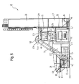
- Fig. 1 shows a side view of a first embodiment of the concrete mixing plant according to the invention, in which a mixer 12 is used becomes. It can be seen in Fig. 1 right one on a bottom plate 14 upright parked on a face lower binder silo or Additive silo container C7, on which an upper silo container C8 is also oriented upright. By opening hatches in the superimposed end faces of the container C7 and C8 can from this a continuous larger silo are formed. It is with these as well as the openable hatches provided in other containers not important, whether this by folding away, a lateral Moving or a complete removal of a hatch door open become. For this reason, the construction of openable hatches will be further History will not be described in detail.
- the lower silo container C7 has in the region of its lower in Fig. 1 End of a funnel 16, which on a lower screw conveyor 18th empties. This passes through the left in Fig. 1 side wall of the lower silo container C7 through a hatch L7 and promotes binder or additive out of it to a vertical screw conveyor 20, which at the in Fig. 1 left side wall of the lower silo container C7 and the upper silo container C8 is fixed and runs there substantially upwards.
- the Vertical screw conveyor 20 with an upper screw conveyor 22nd together and give her binder or additive to Further transport.
- the upper screw conveyor 22 passes through the right in Fig. 1 side wall of the mixer top container C3 by one in this side wall provided openable hatch L3a and ends above one in the mixer attachment container C3 provided binder bag 24, in which the of the Upper conveyor screw 22 brought about binder or additive falls.
- the binder bag 24 passes through the mixer container C2 arranged mixer 12 dosed binder or additive, including in the binder bag 24, if necessary, a scale is installed.
- Fig. 1 In the embodiment shown various means for increasing the stability of the binder silo provided: On the one hand is at the lower end face on which the lower Silo container C7 is attached, a concrete slab 26. To the other are the lower silo container C7 and the upper silo container C8 in Fig. 1 with a plurality of cross struts 28 on the mixer attachment container C3 and on Attached mixer container C2.
- the metered supply of surcharges to the mixer 12 begins in the operation of Transportable concrete mixing plant 10 according to the invention at a Dosing unit container C5, the metering device 34 for dosing the surcharges.
- the metering device comprises 34 for surcharges a weighing conveyor 34a for weighing and Transporting the aggregates and a plurality of feeds 34b for feeding the supplements to the weighing conveyor 34a.
- each feed means 34b is formed as a funnel, the tapers down and up to an openable hatch in the in FIGS. 1 and 8 show the upper side wall of the dosing unit container C5 wide open.
- each grain group can have a particular funnel 34b, so that in this case in the embodiment shown in Fig. 8 the dosing unit container C5 total surcharges with four different grain groups can be mixed.
- Dosing unit container C5 a dosing attachment container C6 with substantially assigned the same length.
- This dosing attachment container C6 is in Operating state disassembled or unfolded in two halves, which side by side and mounted parallel to the dosing unit container C5 on this are.
- In the dosing attachment container C6 are inclined baffles 36th fastened, which walls of the funnels 34 b through opened hatches L5 or L6 in the upper side wall of the dosing unit container C5 and in the lower sidewall of each half of the dosing attachment container C6 extend.
- the side view of Fig. 1 is thereby the effective filling width of the arrangement of funnels 34b in substantially doubled, a doubling of the effective upper Filling cross section of each funnel 34b corresponds.
- additional Baffles 38 which substantially at corners of the halves of the dosing attachment container C6 are rotatably mounted, upwards from the dosing attachment container C6 unfolded.
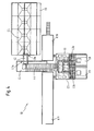
- the shape of this fold-out Baffles 38 is suitably adapted to the direction from the supply of surcharges should be made mainly. So extend the in the embodiment of Figs. 1 and 2 used foldout Baffles 38, the opening of the hopper 34 b substantially to the right above, because the supply of surcharges by one or more wheel loader 40th essentially, as shown in Fig. 2, from the left.
- This task conveyor belt 42 is in the transport state of the dosing unit container shown in Fig. 8 C5 under the cradle conveyor 34a and parallel to it added.
- the Task conveyor 42 through an open hatch L5a in the in the Top view of Fig. 2 lower end face of the dosing unit container C5 pulled out.
- the task conveyor 42 protrudes in this Operating state so far under the cradle conveyor belt 34a that it at its in Fig. 8 right end falling drops reliably can take over.
- this is outside the metering unit container C5 located end of the task conveyor belt 42 via a Steep conveyor 44 for the supply of aggregates to the mixer attachment container C3 arranged.
- this can its lower end advantageously with a baffle plate, chute or the like designed aggregate collecting device 46 provided be.
- this is Steep conveyor belt 44 during transport of the concrete mixing plant according to the invention in the folded state in a steep conveyor belt container C4 completely absorbed.
- a baffle 50th be attached to the mixer attachment container C3 so that it from the Steep conveyor 44 fed promoted surcharges in the Vorsilo 48.
- the mixer container 12 contained the mixer C2 placed on a base of a mixer frame 52, which next to the lower binder silo container C7 on the bottom plate 14 stands.
- This mixer frame 52 is dimensioned such that from Mixer 12 produced concrete through a lower bottom emptying opening 12a of the mixer 12 and opened hatches L2a in the bottom surface of the mixer container C2 in a provided under the stand truck 54 can be drained. With the help of one or more such Truck 54 may be the freshly prepared concrete to the respective Site to be transported on the site.
- Transportable concrete mixing plant also includes a single erected water and / or additive container C11.
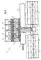
- FIG. 3 and 4 A second embodiment of the transportable invention Concrete mixing plant is shown in Figs. 3 and 4. Compared to the in Figs. 1 and 2 shown embodiment allows this Embodiment a larger concrete production, since they are two mixers used. Components of this second embodiment, the Components of the first embodiment identical or functionally identical are in Figs. 3 and 4 with the same reference numerals as in Fig. 1st and 2 provided.
- Figs. 3 and 4 includes the Mixer container C2 two preferably identical mixer 12. Zur Supply of these two mixers 12 with binder are all this Purpose serving components of the first embodiment in the second Embodiment provided twice. It can thus be seen in FIG. 3 and 4 two lower silo containers C7, on each of which upper silo containers Stand C8. As in the first embodiment, each form a lower silo container C7 and an upper silo container C8 a larger one Silo, from each of which a mixer 12 via a respective hopper 16, a lower binder screw conveyor 18, a binder vertical screw conveyor 20, an upper binder screw conveyor 22nd and a possibly provided with a balance binder bag 24 in one Mixing attachment container C3 is supplied with binder.
- the supply of surcharges to two Vorsilos 48 for surcharges, respectively associated with a mixer 12, also takes place in the second embodiment the concrete mixing plant 10 according to the invention first again via a baffle plates 36, 38 provided with dosing attachment container C6, and a recorded in a dosing unit container C5
- concrete mixing plant is the two mixers 12th containing mixer container C2 on a standing surface of a mixer stand 52.
- FIGS. 5 to 7 A third embodiment of the transportable according to the invention Concrete mixing plant is shown in FIGS. 5 to 7. These Embodiment is intended for large construction sites, where particularly a lot of concrete is needed. For this reason, the in Figs. 5 to 7 shown embodiment of the concrete mixing plant 10 according to the invention two mixer containers C2, each containing two mixers 12. in the Operation, the two mixer container C2 as shown in Fig. 6 can be seen is so juxtaposed, and hatches in the adjacent end faces of the two mixer container C2 opened, that the four mixers 12 substantially in a row stand. On each mixer container C2 is a mixer attachment container C3 set up with the shown in FIGS. 3 and 4 mixer attachment container C3 is substantially identical and thus for each mixer 12th a Vorsilo 48 for surcharges and a binder bag 24 contains.
- each mixer 12 is a complete set of binder supply components or additive assigned, d. H. the silo containers C7 and C8 as well as the Augers 18, 20 and 22.
- This Concrete collecting belt 60 conveyed in the direction of running falls at the end of the upper concrete collecting belt 60 onto a lower concrete conveyor belt 62.
- This Lower concrete conveyor belt 62 is also completely in transit
- Loading container C1 is added and will operate the system 10 so far through an open hatch L1 a in the right in Fig. 7 end wall pulled out of the loading container C1 that it is at his in-loading container C1 remaining end of the upper concrete collection belt 60th to safely collect falling concrete and to one beside the loading container C1 provided truck 54 can transport.
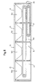
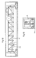
- Fig. 10 shows a side view of the lower silo container C7 of Transportable concrete mixing plant 10 according to the invention, in which the Simplifying the appearance of the front side wall is removed. you recognizes the funnel 16 fixed firmly in the lower silo container C7 and the fixed on its in Fig. 10 right end face Stabilization purposes fortified concrete slab 26. It also recognizes a for transport in the container C7 recorded lower auger 18th and a disassembled mixer frame 52. It is understood that these components during transport by in Fig. 10, not shown Securing means, such. As belts, be secured against slipping can.
- Fig. 11 shows a side view of an upper silo container C8 of Concrete mixing plant according to the invention 10.
- this container C8 are during transport, the bottom plate 14, the vertical screw conveyor 20, the upper auger 22, a replacement auger 22e, which is in operation at the upper silo container C8 fixed ladder 30 and the railing device 32 recorded.
- Figs. 12 and 13 show a side and front view of another, respectively upper silo-container C8, wherein the front side or end wall of the Containers in turn removed for clarity.
- the Container C8 is received during transport a concrete paver 64, the the construction site for concreting roads, runways and the like can be used. It is understood that in the transport entrained containers, in particular the often empty entrained upper Binder silo containers C8 optionally also others, at the construction site needed items can be carried.
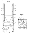
- Figs. 14, 15 and 16 illustrate another embodiment of the Transportable concrete mixing plant according to the invention 10.
- a pressure conveying device 66 provided to contain the substances contained in a silo container C7, C8, So for example, binders and / or additives, from this To carry out container C7, C8.
- This is at the bottom of the lower silo container C7 a collection vessel 68 installed.
- a motorized pressure-tight Closure flap 68a provided so that they just below the bottom End of the mounted in the silo container C7 funnel 16 is located.
- the filling of the collecting vessel 68 is done as follows: First the silo containers C7, C8 filled with binder or additive. In the in Figs. 14 to 16 illustrated embodiment, this is done in the lower area of the silo container C7 attached and outward openable binder feed connection elements 78, to which in itself a known manner, a connecting hose to a with a pressure conveying device equipped with binder or additives Trucks can be connected. The of this truck conveyed with pressure to the binder feed connection elements 78 Fabrics are pressed into binder feed conduits 80 which are incorporated in the Corners of the silo containers C7, C8 in Figs.
- the promoted in the silo containers C7, C8 substances fill the Funnel 16 and the overlying areas of the silo containers C7, C8 and are at a certain pressure on the pressure-tight Closure flap 68a of the receptacle 68 on.
- motorized Opening the shutter 68a falls through the opening period certain amount of the binder or additive in the collection vessel 68, which by the subsequent closing of the flap 68a at the top again pressure-tight is completed.
- Binder or additive falls into one in the lower part of the Binder intermediate container C12 installed hopper 74, which over a corresponding hatch in the bottom of the binder intermediate container C12 over a rotary valve 76 opens, which above a Binder bag 24 is disposed in a mixer attachment container C3.
- the rotary valve 76 not only ensures the pressure decoupling between the pressure in the binder intermediate container C12 promoted binder or additive and in the binder bag 24 to be weighed binder or additive, but allowed by Adjustment of their running speed in addition a predosing of in the binder bag 24 precisely metered binder or Additive.
- the rotary valve 76 and the binder pocket 24 are integrally formed.
- the delivery hose 72 does not necessarily have in the in Fig. 14 shown approximately perpendicular to the outer wall of the silo container C7, C8 go up. Rather, the use offers Such a delivery hose 72 just the advantage of binder or Additive in a flexible way from silo containers C7, C8 to an optionally distant binder intermediate container C12 on a mixer attachment container To promote C3.
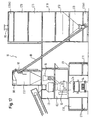
- FIGS. 17, 18 and 19 illustrate another embodiment of the invention Transportable concrete mixing plant according to the invention 10.
- binder oil container C13 are used with stacked in a substantially horizontal orientation parallel to each other are.
- Fig. 17 right five such silo containers C13 with in the Plane lying horizontally horizontal longitudinal axis shown.
- the ground and Ceiling surfaces of these silo containers C13 are after transport in the construction of the transportable concrete mixing plant according to the invention 10 has been removed, so that in the region of the transition between two silo containers C13 almost no niches, corners u. Like. occur in which binders could undesirably accumulate.
- These five silo containers C13 are placed on a lowest silo container C13A1 and completed at the top by a top silo container C13A2. As can be seen in Fig. 17, have the lowest silo container C13A1 and the top silo container C13A2 half the height of the five other silo containers C13 on.
- These two containers are C13A1, C13A2 namely around the halves of a divisible silo closure container C13A, the transport of the concrete mixing plant 10 of the invention is carried as a closed container and the construction of the Concrete mixing plant 10 is divided into the two halves shown.
- This Silo End Container C13A can be used during transport components which are required in the operating condition of the system 10 on the silo, for example, in Fig. 17 at the top of the uppermost container C13A2 shown filter 90, which displaced from the filling of the silo Air binder filters out.
- the concrete mixing plant 10 according to the invention is also in the in Figs. 17-19 illustrated binder from the lower part of a Binder silos, which here through the five silo containers C13 den lowest silo container C13A1 and the top silo container C13A2 is formed, conveyed out by a screw conveyor assembly.
- this promotion takes place in the embodiment of FIGS. 17-19 not directly to a arranged in a mixer attachment container C3 Binder pocket 24, but similar to that shown in Fig. 14 Embodiment in a binder intermediate container C12, the on a mixer attachment container C3 is set up.
- binder inclined screw conveyor 88 which as can be seen in Fig. 17, directly from the lowest silo container C13A1 extends to the binder intermediate container C12. Because of this oblique course, the binder slant conveyor screw 88 can be shorter be designed as the sum of the lengths of the three, for example, in Fig. 1 shown screw conveyors 18, 20, 22, each horizontal or vertical which leads to cost savings and facilitates assembly, since the alignment of several augers to each other deleted.
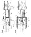
- FIG. 18 installation with a mixer
- FIG. 19 plant with two mixers
- two juxtaposed "towers" of Silo containers C13 provided, with the horizontal orientation parallel stacked on top of each other.
- each Tower becomes binder in each case by a binder inclined screw conveyor 88 promoted.
- the two Binder screw conveyors 88 each at a corresponding Chute, which leads to two binder intermediate containers C12, which each above a binder pocket 24 for supplying a mixer 12 are arranged.
- the binder intermediate container C12 is further provided with a in Fig. 17 Dashed line binder supply line 92 equipped, the similar to the illustrated in Figs. 14-16 silo containers C7, C8 a filling of the binder intermediate container C12 from a binder supplying trucks o. The like. Enables, for example by means of a above-described pressure conveying device.
- the binder intermediate container C12 can be filled in two different ways, namely on the one hand from the silo containers C13 on the binder-inclined screw conveyor 88 and on the other hand from a delivery vehicle via the binder supply line 92, may be a continuous supply of Mixer 12 can be ensured with binder with high security.
- a Mixer container C2 arranged two more containers, namely one Mixer attachment container C3 and on this turn a binder intermediate container C12.
- the resulting total weight concludes a list of the mixer container C2 on a mixer stand 52, As shown for example in Fig. 1, usually off. Nevertheless the opportunity to offer concrete directly from the mixer container C2 in a truck 54 provided under the mixer container C2 o. The like.
- the mixer container C2 in the in Figs. 17-19 shown at its ends on each other Containers placed so that a lower middle area of the mixer container C2, in which at least one openable hatch L2a to Removal of concrete is located, freely accessible.
- Transportable concrete mixing plant 10 can be used, which is the have the same height as the container C9, C10, so that in this case the mixer container C2 would be higher.
- Important regarding the Choice of containers to support the mixer container C2 his left and right ends are used is that of Mixer container C2 is sufficiently high to be a hassle-free Retracting the truck 54 to ensure, but not so high is that discharged concrete could fall next to the truck 54 or could fall on its cargo area at too high a speed.
- FIGS. 20-22 of the invention transportable concrete mixing plant 10 is in Figs. 17 - 19 presented similarly. In the following, therefore, only the differences become the embodiment described above.
- Binder intermediate container C12 on a mixer attachment container C3 placed above the binder bag 24 provided in it.
- the Binder screw conveyor screw 88 conveys binders from the silo containers C13 in this embodiment, however, not in the binder intermediate container C12, but rather in a binder intermediate container 84, the top right in Fig. 20 in the mixer attachment container C3 is provided. From this binder intermediate container In turn, binder is by means of a screw conveyor 86 in the Binder bag 24 promoted. It is understood that depending on the size and relative arrangement of the binder bag 24 and the Binder intermediate container 84 instead of a screw conveyor 86 also a simple chute or slide or a small one Pressure conveying device may be provided.
- the binder intermediate container C12 is in this embodiment also equipped with a binder feed line 92 and can therefore, as already explained above, from a binder supplying Truck o. The like. Be filled.
- the two “Towers" from silo containers C13 which are essentially horizontal Longitudinal axis are stacked parallel to each other, spaced from each other placed and connected by cross struts 94 together. hereby can be a greater stability of the silo container C13 against falling over achieve what is particularly important when the Transportable concrete mixing plant 10 according to the invention at construction sites is used, which are exposed to strong wind.
- the transportable concrete mixing plant according to the invention 10 basically have any number of mixers 12 can. Furthermore, it is possible to have multiple mixers by a single Binder silo with binder to provide a conveyor belt for Binder similar to that presented in the third embodiment, shiftable aggregate conveyor between different operating positions 56 with optional reversible direction for use can come. Furthermore, the number of dosing unit containers used C5 with associated dispensing container C6 depending on the number of used mixer 12 and the speed of their concrete production optionally also varied with respect to the presented embodiments become. It is also possible to add surcharges to the Vorsilos 48 more than a steep conveyor belt 44 use. Furthermore, the Relative arrangement of the container while fully maintaining the function of Transportable concrete mixing plant 10 according to the invention of course compared to the presented embodiments be changed without departing from the scope of the invention.
Landscapes
- Preparation Of Clay, And Manufacture Of Mixtures Containing Clay Or Cement (AREA)
- On-Site Construction Work That Accompanies The Preparation And Application Of Concrete (AREA)
- Cultivation Receptacles Or Flower-Pots, Or Pots For Seedlings (AREA)
- Packging For Living Organisms, Food Or Medicinal Products That Are Sensitive To Environmental Conditiond (AREA)
- Lubricants (AREA)
- Curing Cements, Concrete, And Artificial Stone (AREA)
- Mixers With Rotating Receptacles And Mixers With Vibration Mechanisms (AREA)
- Fertilizers (AREA)
Abstract
Description
- Fig. 1
- eine Seitenansicht einer ersten Ausführungsform der erfindungsgemäßen transportierbaren Betonmischanlage mit einem Mischer im Betriebszustand;
- Fig. 2
- eine Draufsicht auf die Betonmischanlage gemäß Fig. 1;
- Fig. 3
- eine Seitenansicht einer zweiten Ausführungsform der erfindungsgemäßen transportierbaren Betonmischanlage mit zwei Mischern im Betriebszustand;
- Fig. 4
- eine Draufsicht auf die Betonmischanlage gemäß Fig. 3;
- Fig. 5
- eine Seitenansicht einer dritten Ausführungsform der erfindungsgemäßen transportierbaren Betonmischanlage mit vier Mischern im Betriebszustand;
- Fig. 6
- eine Draufsicht auf die Betonmischanlage gemäß Fig. 5;
- Fig. 7
- eine Teil-Vorderansicht der Betonmischanlage gemäß Fig. 5;
- Fig. 8
- eine Seitenansicht des Dosiereinheit-Containers der erfindungsgemäßen transportierbaren Betonmischanlage im Transportzustand;
- Fig. 9
- eine Vorderansicht des Dosieraufsatz-Containers der erfindungsgemäßen transportierbaren Betonmsichanlage im Transportzustand;
- Fig. 10
- eine Seitenansicht eines unteren Bindemittelsilo-Containers der erfindungsgemäßen transportierbaren Betonmischanlage im Transportzustand;
- Fig. 11
- eine Seitenansicht eines oberen Bindemittelsilo-Containers der erfindungsgemäßen transportierbaren Betonmischanlage im Transportzustand;
- Fig. 12
- eine Seitenansicht eines weiteren oberen BindemittelsiloContainers mit einem Betonfertiger im Transportzustand;
- Fig. 13
- eine Vorderansicht des Bindemittelsilo-Containers gemäß Fig. 12;
- Fig. 14
- eine Seitenansicht einer weiteren Ausführungsform der erfindungsgemäßen transportierbaren Betonmischanlage mit einer Druckluftfördervorrichtung;
- Fig. 15
- eine vergrößerte Teil-Seitenansicht des Silo-Containers der Ausführungsform von Fig. 14; und
- Fig. 16
- eine Draufsicht auf den entlang der Linie A-A in Fig. 15 geschnittenen Silo-Container;
- Fig. 17
- eine Seitenansicht einer weiteren Ausführungsform der erfindungsgemäßen transportierbaren Betonmischanlage mit einem Bindemittel-Zwischencontainer und einer Förderschneckenanordnung;
- Fig. 18
- eine Draufsicht auf die Betonmischanlage von Fig. 17 bei Verwendung eines Mischers;
- Fig. 19
- eine Draufsicht auf die Betonmischanlage von Fig. 17 bei Verwendung von zwei Mischern;
- Fig. 20
- eine Seitenansicht einer weiteren Ausführungsform der erfindungsgemäßen transportierbaren Betonmischanlage mit einem Bindemittel-Zwischenbehälter in einem MischeraufsatzContainer;
- Fig. 21
- eine Draufsicht auf die Betonmischanlage von Fig. 20 bei Verwendung eines Mischers;
- Fig. 22
- eine Draufsicht auf die Betonmischanlage von Fig. 20 bei Verwendung von zwei Mischern.
Claims (62)
- Transportierbare Betonmischanlage (10), umfassend eine Mehrzahl von lösbar miteinander verbindbaren Mischanlagen-Komponenten, die beim Transport in einer Mehrzahl von Containern (C1, C2, C3, C4, C5, C6, C7, C8, C9, C10, C11, C12, C13) aufgenommen sind, wobei wenigstens ein Teil dieser Container (C1, C2, C3, C4, C5, C6, C7, C8, C9, C10, C11, C12, C13), vorzugsweise sämtliche dieser Container, im Betriebszustand der Mischanlage (10) als Tragestruktur für Mischanlagen-Komponenten oder/und Behälter für Beton-Ausgangsstoffe dienen, wobei in wenigstens einem Mischer-Container (C2) wenigstens ein Mischer (12) vorgesehen ist, dadurch gekennzeichnet, dass der wenigstens eine Mischer-Container (C2) in seinen Endbereichen auf Containern getragen ist, wobei einer dieser Container ein Steuerstand-Container (C10) ist.
- Transportierbare Betonmischanlage (10) nach Anspruch 1, dadurch gekennzeichnet, daß die Container (C1, C2, C3, C4, C5, C6, C7, C8, C9, C10, C11, C12, C13) Norm-Schiffscontainer sind oder zu Norm-Schiffscontainern zusammensetzbar sind, die nach den internationalen Vorgaben, insbesondere per Schiff, Bahn und Lkw, einheitlich transportiert werden können.
- Transportierbare Betonmischanlage (10) nach Anspruch 1 oder 2, dadurch gekennzeichnet, daß wenigstens einige Container (C1, C2, C3, C4, C5, C6, C7, C8, C9, C10, C11, C12, C13) öffenbare Luken (L1, L1a, L2, L2a, L3, L3a, L3b, L4, L4a, L5, L 5a, L6, L7) aufweisen, durch die hindurch im Betriebszustand der Mischanlage (10) in verschiedenen Containern (C1, C2, C3, C4, C5, C6, C7, C8, C9, C10, C11, C12, C 13) wenigstens teilweise aufgenommene Mischanlagen-Komponenten zusammenwirken können.
- Transportierbare Betonmischanlage (10) nach einem der vorhergehenden Ansprüche, dadurch gekennzeichnet, daß sie wenigstens einen Mischer-Container (C2) aufweist, der wenigstens einen Betonmischer (12) zum Mischen von Zuschlägen, von bevorzugt zementhaltigem Bindemittel, von Wasser und von Zusatzmitteln sowie Zusatzstoffen zur Herstellung von Beton enthält.
- Transportierbare Betonmischanlage (10) nach Anspruch 4, dadurch gekennzeichnet, daß die im Betriebszustand oberhalb jedes Mischers (12) befindliche Wand des Mischercontainers (C2) über jedem Mischer (12) eine öffenbare Luke (L2) aufweist.
- Transportierbare Betonmischanlage (10) nach Anspruch 5, dadurch gekennzeichnet, daß sie wenigstens einen im Betriebszustand der Mischanlage (10) auf dem Mischer-Container (C2) angeordneten Mischeraufsatz-Container (C3) umfaßt, der Beschickungsmittel zum Einführen von Bindemittel, vorzugsweise Zement, und von Zuschlägen sowie ggf. Zusatzstoffen in jeden Mischer (12) durch die in der oberen Wand des Mischer-Containers (C2) befindlichen öffenbaren Luken (L2) und durch diesen Luken (L2) gegenüberliegende öffenbare Luken (L3) in der Bodenwand des Mischeraufsatz-Containers (C3) hindurch enthält.
- Transportierbare Betonmischanlage (10) nach Anspruch 6, dadurch gekennzeichnet, daß die Beschickungsmittel für jeden Mischer (12) ein Vorsilo (48) für Zuschläge und eine Bindemitteltasche (24) für Bindemittel sowie ggf. für Zusatzstoffe umfassen.
- Transportierbare Betonmischanlage (10) nach Anspruch 7, dadurch gekennzeichnet, daß die Bindemitteltasche (24) sowie ggf. die Zusatzstofftasche eine Waage enthält.
- Transportierbare Betonmischanlage (10) nach einem der Ansprüche 6 bis 8, dadurch gekennzeichnet, daß ein durch eine geöffnete Luke (L3a) in einer Wand des Mischeraufsatz-Containers (C3) in diesen hinein führendes Bindemittel-Fördermittel (22) zum Einbringen von Bindemittel sowie ggf. Zusatzstoff in den Mischeraufsatz-Container (C3) vorgesehen ist.
- Transportierbare Betonmischanlage (10) nach Anspruch 9, dadurch gekennzeichnet, daß das in den Mischeraufsatz-Container (C3) führende Bindemittel-Fördermittel (22) eine Förderschnecke ist.
- Transportierbare Betonmischanlage (10) nach einem der Ansprüche 6 bis 10, dadurch gekennzeichnet, daß bei Verwendung von wenigstens zwei Mischern (12) ein Zuschlag-Fördermittel (56) mit wahlweise umschaltbarer Laufrichtung zum Zuführen der Zuschläge zu den jeweils einem Mischer (12) zugeordneten Beschickungsmitteln (48) vorgesehen ist.
- Transportierbare Betonmischanlage (10) nach Anspruch 11, dadurch gekennzeichnet, daß bei Verwendung von wenigstens drei Mischern (12) das Zuschlag-Fördermittel (56) über den Beschickungsmitteln (48) für die Zuschläge zwischen mehreren Betriebsstellungen hinund herfahrbar ist, in denen jedes Ende des Zuschlag-Fördermittels (56) einem Beschickungsmittel (48) für Zuschläge zugeordnet ist.
- Transportierbare Betonmischanlage (10) nach Anspruch 11 oder 12, dadurch gekennzeichnet, daß das Zuschlag-Fördermittel (56) ein Förderband ist.
- Transportierbare Betonmischanlage (10) nach einem der Ansprüche 6 bis 13, dadurch gekennzeichnet, daß ein wenigstens eine Wand des Mischeraufsatz-Containers (C3) durch eine geöffnete Luke (L3b) durchlaufendes Steilfördermittel (44) zum Einbringen der Zuschläge in den Mischeraufsatz-Container (C3) vorgesehen ist.
- Transportierbare Betonmischanlage (10) nach Anspruch 14, dadurch gekennzeichnet, daß das Steilfördermittel (44) ein Förderband ist, welches beim Transport in zusammengeklapptem Zustand in einem Steilförderband-Container (C4) aufgenommen ist.
- Transportierbare Betonmischanlage (10) nach einem der Ansprüche 4 bis 15, dadurch gekennzeichnet, daß die im Betriebszustand untere Wand des Mischer-Containers (C2) unter jedem Mischer (12) eine zur Entnahme von Beton aus dem Mischer-Container (C2) öffenbare Luke (L2a) aufweist.
- Transportierbare Betonmischanlage (10) nach Anspruch 16, dadurch gekennzeichnet, daß der Mischer-Container (C2) auf einer Standfläche eines Mischergerüsts (52) aufgestellt ist, welches derart dimensioniert ist, daß Beton durch die öffenbaren Luken (L2a) zur Entnahme von Beton aus dem Mischer-Container (C2) in einen unter der Standfläche bereitgestellten Lastkraftwagen (54) oder dgl. abgelassen werden kann.
- Transportierbare Betonmischanlage (10) nach Anspruch 16, dadurch gekennzeichnet, daß der Mischer-Container (C2) im Betriebszustand der Anlage auf einem Verlade-Container (C1) steht, in dessen Deckenwand den öffenbaren Luken (L2a) der Bodenwand des Mischer-Containers (C2) gegenüberliegende öffenbare Luken (L1) vorgesehen sind.
- Transportierbare Betonmischanlage (10) nach Anspruch 18, dadurch gekennzeichnet, daß an einer Stirnwand des Verlade-Containers (C1) eine öffenbare Luke (L1a) vorgesehen ist, die von einer beim Transport vollständig im Verlade-Container (C1) aufgenommenen Betonfördervorrichtung zum Fördern des Betons, beispielsweise zu einem neben dem Verlade-Container bereitgestellten Lastkraftwagen oder dergleichen, durchsetzt wird.
- Transportierbare Betonmischanlage (10) nach Anspruch 19, dadurch gekennzeichnet, daß die Betonfördervorrichtung ein im Betriebszustand vollständig im Verlade-Container (C1) aufgenommenes oberes Betonsammelband (60) und ein die öffenbare Luke (L1 a) in der Stirnwand des Verlade-Containers (C1) im Betriebszustand durchsetzendes unteres Betonförderband (62) umfaßt.
- Transportierbare Betonmischanlage (10) nach einem der vorhergehenden Ansprüche, dadurch gekennzeichnet, daß sie wenigstes einen Bindemittel-Silo-Container (C7, C8) als Aufbewahrungsmittel für Bindemittel oder dergleichen umfaßt sowie ggf. einen entsprechenden Silo-Container für Betonzusatzstoff.
- Transportierbare Betonmischanlage (10) nach Anspruch 21, dadurch gekennzeichnet, daß jeder Bindemittelsilo- bzw. Zusatzstoffsilo-Container (C7, C8) hochkant orientiert auf seiner Stirnfläche steht.
- Transportierbare Betonmischanlage (10) nach Anspruch 21 oder 22, dadurch gekennzeichnet, daß wenigstens zwei Bindemittelsilo- bzw. Zusatzstoffsilo-Container (C7, C8) nebeneinander oder aufeinander aufgestellt sind.
- Transportierbare Betonmischanlage (10) nach Anspruch 22 oder 23, dadurch gekennzeichnet, daß jeder hochkant aufgestellte Bindemittelsilo- bzw. Zusatzstoffsilo-Container (C7, C8) zur Stabilisierung mittels Querstreben (28) am Mischeraufsatz-Container (C3) und/oder am Mischer-Container (C2) und/oder am Verlade-Container (C1) bzw. am Mischergerüst (52) befestigt ist.
- Transportierbare Betonmischanlage (10) nach einem der Ansprüche 21 bis 24, dadurch gekennzeichnet, daß jeder nicht auf einem weiteren Silo-Container (C7, C8) stehende Silo-Container (C7) und der Verlade-Container (C1) bzw. das Mischergerüst (52) auf einer gemeinsamen Bodenplatte (14) befestigt sind.
- Transportierbare Betonmischanlage (10) nach einem der Ansprüche 21 bis 25, dadurch gekennzeichnet, daß jeder nicht auf einem weiteren Silo-Container (C7, C8) stehende Silo-Container (C7) in seinem im Betriebszustand unteren Bereich einen Trichter (16) enthält, dessen oberer Querschnitt im wesentlichen dem Querschnitt des Silo-Containers (C7) entspricht und der sich nach unten hin verjüngt.
- Transportierbare Betonmischanlage (10) nach einem der Ansprüche 21 bis 26, dadurch gekennzeichnet, daß jeder nicht auf einem weiteren Silo-Container (C7, C8) stehende Silo-Container (C7) an seiner im Betriebszustand unten befindlichen Stirnfläche eine Betonplatte (26) zur Stabilisierung aufweist.
- Transportierbare Betonmischanlage (10) nach Anspruch 26 oder 27, dadurch gekennzeichnet, daß im Betriebszustand unter der Trichteröffnung ein Bindemittel- bzw. Zusatzstoff-Fördermittel (18) angeordnet ist, welches eine Seitenwand des Silo-Containers (C7) durch eine geöffnete Luke (L7) durchsetzt.
- Transportierbare Betonmischanlage (10) nach Anspruch 28, dadurch gekennzeichnet, daß das Bindemittel- bzw. Zusatzstoff-Fördermittel (18) eine Förderschnecke ist.
- Transportierbare Betonmischanlage (10) nach Anspruch 28 oder 29, dadurch gekennzeichnet, daß das Bindemittel- bzw. Zusatzstoff-Fördermittel (18) mit einem an einer Außenwand des Silo-Containers (C7) im wesentlichen senkrecht oder schräg nach oben verlaufenden Senkrechtfördermittel (20) derart zusammenwirkt, daß es diesem Bindemittel bzw. Zusatzstoff zum Weiterfördern übergeben kann.
- Transportierbare Betonmischanlage (10) nach Anspruch 30, dadurch gekennzeichnet, daß das Senkrecht- bzw. Schrägfördermittel (20) eine Förderschnecke ist.
- Transportierbare Betonmischanlage (10) nach Anspruch 30 oder 31, dadurch gekennzeichnet, daß das Senkrecht- bzw. Schrägfördermittel (20) mit dem teilweise im Mischeraufsatz-Container (C3) verlaufenden Bindemittel- bzw. Zusatzstoff-Fördermittel (22) derart zusammenwirkt, daß es diesem Bindemittel bzw. Zusatzstoff zum Weiterfördern übergibt.
- Transportierbare Betonmischanlage (10) nach einem der Ansprüche 21 bis 32, dadurch gekennzeichnet, daß ferner Leitern (30), Sicherheitsgeländer (32) und dergleichen außen am Silo-Container (C7, C8) vorgesehen sind, welche beim Transport in einem, vorzugsweise diesem Container (C7, C8) aufgenommen sind.
- Transportierbare Betonmischanlage (10) nach einem der Ansprüche 21 bis 33, dadurch gekennzeichnet, daß ein Betonfertiger (64) und/oder eine Arbeitsbühne oder dergleichen in einem Container, vorzugsweise einem Silo-Container (C7, C8) beim Transport aufgenommen ist.
- Transportierbare Betonmischanlage (10) nach einem der vorhergehenden Ansprüche, dadurch gekennzeichnet, daß sie wenigstens einen Dosiereinheit-Container (C5) umfaßt, der eine Dosiervorrichtung (34) zum Dosieren der Zuschläge enthält.
- Transportierbare Betonmischanlage (10) nach Anspruch 35, dadurch gekennzeichnet, daß die Dosiervorrichtung (34) für Zuschläge wenigstens ein Wiege-Förderband (34a) zum Wiegen und Transportieren der Zuschläge und wenigstens ein dem Wiege-Förderband (34a) zugeordnetes Beschickungsmittel (34b) aufweist.
- Transportierbare Betonmischanlage (10) nach Anspruch 36, dadurch gekennzeichnet, daß jedes Beschickungsmittel (34b) durch einen oberhalb des Wiege-Förderbands (34a) angeordneten Trichter gebildet ist, der sich nach unten verjüngt und nach oben zu einer öffenbaren Luke (L5) in der im Betriebszustand oberen Seitenwand des Dosiereinheit-Containers (C5) hin weit öffnet.
- Transportierbare Betonmischanlage (10) nach Anspruch 37, dadurch gekennzeichnet, daß jedem Dosiereinheit-Container (C5) ein Dosieraufsatz-Container (C6) mit im wesentlichen gleicher Länge zugeordnet ist, dessen Hälften im Betriebszustand nebeneinander parallel zum Dosiereinheit-Container (C5) orientiert auf diesem aufgesetzt sind und die mit Hilfe einer Prallblecheinrichtung sowie öffenbarer Luken (L5, L6) in der oberen Seitenwand des Dosiereinheit-Containers (C5) und in der unteren Seitenwand jeder Hälfte des Dosieraufsatz-Containers (C6) den effektiven oberen Einfüllquerschnitt jedes Trichters (34b) im Dosiereinheit-Container (C5) vergrößern.
- Transportierbare Betonmischanlage (10) nach Anspruch 38, dadurch gekennzeichnet, daß die Prallblecheinrichtung fest im Dosieraufsatz-Container (C6) angeordnete, schräg verlaufende Prallbleche (36) umfaßt, die im Betriebszustand die Wände jedes Trichters (34b) im Dosiereinheit-Container (C5) nach oben in die Hälften des Dosieraufsatz-Containers (C6) hinein verlängern.
- Transportierbare Betonmischanlage (10) nach Anspruch 38 oder 39, dadurch gekennzeichnet, daß die Prallblecheinrichtung ferner Prallbleche (38) umfaßt, die im wesentlichen an Ecken der Hälften des Dosieraufsatz-Containers (C6) drehbar gelagert sind und im Betriebszustand derart aus dem Dosieraufsatz-Container (C6) geklappt sind, daß sie die Trichteröffnung nach oben vergrößern.
- Transportierbare Betonmischanlage (10) nach einem der Ansprüche 36 bis 40, dadurch gekennzeichnet, daß im Dosiereinheit-Container (C5) ferner ein unter dem Wiege-Förderband (34a) parallel zu diesem verlaufendes, in Längsrichtung durch eine öffenbare Luke (L5a) in einer Stirnfläche des Dosiereinheit-Containers (C5) teilweise aus dem Dosiereinheit-Container (C5) verlagerbares Aufgabe-Fördermittel (42) vorgesehen ist.
- Transportierbare Betonmischanlage (10) nach Anspruch 41, dadurch gekennzeichnet, daß das Aufgabe-Fördermittel (42) ein Förderband ist.
- Transportierbare Betonmischanlage (10) nach Anspruch 41 oder 42, dadurch gekennzeichnet, daß das im Betriebszustand außerhalb des Dosiereinheit-Containers (C5) befindliche Ende des Aufgabe-Fördermittels (42) über dem Steilfördermittel (44) für die Zufuhr von Zuschlägen zum Mischeraufsatz-Container (C3) angeordnet ist.
- Transportierbare Betonmischanlage (10) nach einem der vorhergehenden Ansprüche, dadurch gekennzeichnet, daß sie zusätzlich einen Zusatzmittel-Container (C9) zur Aufnahme von Beton-Zusatzmitteln umfaßt.
- Transportierbare Betonmischanlage (10) nach einem der vorhergehenden Ansprüche, dadurch gekennzeichnet, daß sie zusätzlich einen Steuerstand-Container (C10) umfaßt, in dem ein Steuerstand zum Steuern der Komponenten der Betonmischanlage (10) untergebracht ist.
- Transportierbare Betonmischanlage (10) nach einem der vorhergehenden Ansprüche, dadurch gekennzeichnet, daß sie zusätzlich einen Wasser-Container (C11) umfaßt bzw. einen Container, der Wasser und/oder Betonzusatzmittel aufnimmt.
- Transportierbare Betonmischanlage (10) nach einem der vorhergehenden Ansprüche, die durch Abdeckung, Isolierung, Abschottung, Erwärmen bzw. Heizen (mit Warmluft, Heißdampf, Heizspirale usw.) der einzelnen Mischanlagen-Komponenten (insbesondere Mischer-Container (C2) samt Mischeraufsatz-Container (C3), Förderbänder (34a, 44, 56, 62), Dosiereinheit-Container (C5), Zusatzmittel- (C9) und Wasser-Container (C11) samt Förderleitungen) einen Mischbetrieb auch bei Umgebungstemperaturen unter 0 °C ermöglicht.
- Transportierbare Betonmischanlage (10) nach einem der Ansprüche 1 bis 47, dadurch gekennzeichnet, daß sie eine Druckfördervorrichtung (66), bevorzugt Druckluftfördervorrichtung, zur Druckförderung aus wenigstens einem Silo-Container (C7) aufweist.
- Transportierbare Betonmischanlage (10) nach Anspruch 48, dadurch gekennzeichnet, daß die Druckfördervorrichtung (66) ein Sammelgefäß (68) mit einem Kompressor (70) und einen an das Sammelgefäß (68) angeschlossenen Förderschlauch (72) umfaßt.
- Transportierbare Betonmischanlage (10) nach einem der Ansprüche 6 bis 49, dadurch gekennzeichnet, daß sie wenigstens einen Bindemittel-Zwischencontainer (C12) zur Zwischenlagerung von Bindemittel aufweist, der vorzugsweise auf wenigstens einem Mischeraufsatz-Container (C3) aufgestellt ist.
- Transportierbare Betonmischanlage (10) nach Anspruch 49 und Anspruch 50, dadurch gekennzeichnet, daß der Förderschlauch (72) in den wenigstens einen Bindemittel-Zwischencontainer (C12) mündet.
- Transportierbare Betonmischanlage (10) nach Anspruch 50 oder 51, dadurch gekennzeichnet, daß der wenigstens eine Bindemittel-Zwischencontainer (C12) einen Trichter (74) enthält, der in eine Zellradschleuse (76) mündet, welche über einer Bindemitteltasche (24) in einem Mischeraufsatz-Container (C3) angeordnet ist.
- Transportierbare Betonmischanlage (10) nach Anspruch 49 oder einem der Ansprüche 50 bis 52, sofern auf Anspruch 49 rückbezogen, dadurch gekennzeichnet, daß das Sammelgefäß (68) und der Kompressor (70) im unteren Bereich des Silo-Containers (C7) angeordnet sind.
- Transportierbare Betonmischanlage (10) nach einem der vorhergehenden Ansprüche, dadurch gekennzeichnet, daß sie Bindemittelsilo- oder/und Zusatzstoffsilo-Container (C13) aufweist, die im Betriebszustand mit im Wesentlichen horizontaler Orientierung parallel aufeinander gestapelt sind.
- Transportierbare Betonmischanlage (10) nach Anspruch 54, dadurch gekennzeichnet, daß die mit im Wesentlichen horizontaler Orientierung parallel aufeinander gestapelten Bindemittelsilo- oder/und Zusatzstoffsilo-Container (C13) jeweils entfernbare Boden- und Deckenflächen aufweisen.
- Transportierbare Betonmischanlage (10) nach Anspruch 54 oder 55, dadurch gekennzeichnet, daß sie einen im Wesentlichen in zwei Hälften teilbaren Siloabschluß-Container (C13A) aufweist, dessen Hälften (C13A1, C 13A2) im Betriebszustand den untersten (C13A1) beziehungsweise den obersten (C13A2) Container einer Gruppe parallel aufeinander gestapelter Silo-Container (C13) bilden.
- Transportierbare Betonmischanlage (10) nach einem der Ansprüche 6 bis 56, dadurch gekennzeichnet, daß vorzugsweise in einem Mischeraufsatz-Container (C3) wenigstens ein Bindemittel-Zwischenbehälter (84) zur Zwischenlagerung von Bindemittel angeordnet ist.
- Transportierbare Betonmischanlage (10) nach Anspruch 57, dadurch gekennzeichnet, daß ein Bindemittel-Förderorgan (86), vorzugsweise eine Bindemittel-Förderschnecke, zur Förderung von Bindemittel vom wenigstens einen Bindemittel-Zwischenbehälter (84) in eine Bindemitteltasche (24) im Mischeraufsatz-Container (C3) angeordnet ist.
- Transportierbare Betonmischanlage (10) nach Anspruch 57 oder 58, dadurch gekennzeichnet, daß sie zur Förderung von Bindemittel und/oder Zusatzstoffen aus einem Silo-Container (C7, C8, C13) und/oder einem Transportfahrzeug in einen Bindemittel-Zwischenbehälter (84) und/oder einen Bindemittel-Zwischencontainer (C12) ausgebildet ist, vorzugsweise eine Förderschneckenanordnung (18, 20, 22; 88) und/oder eine Druckfördervorrichtung (66) aufweist.
- Transportierbare Betonmischanlage (10) nach einem der Ansprüche 4 bis 59, dadurch gekennzeichnet, daß ein Mischer-Container (C2) im Betriebszustand der Anlage an seinen Enden auf jeweils wenigstens einem anderen Container (C1, C2, C3, C4, C5, C6, C7, C8, C9, C10, C11, C12, C13) derart aufgestellt ist, dass Beton durch die öffenbaren Luken (L2a) zur Entnahme von Beton aus dem Mischer-Container (C2) in einen unter dem Mischer-Container (C2) bereitgestellten Lastkraftwagen (54) oder dergleichen abgelassen werden kann.
- Dosieraufsatz zum Vergrößern des effektiven Auffangquerschnitts eines Trichters einer Dosiereinheit, vorzugsweise eines Dosiereinheit-Containers einer transportierbaren Betonmischanlage (10) nach einem der Ansprüche 35 bis 43, dadurch gekennzeichnet, daß der Dosieraufsatz durch einen in zwei Hälften teilbaren Dosieraufsatz-Container gebildet ist, dessen nebeneinander auf die Dosiereinheit aufgesetzte Hälften mittels fester Prallbleche im Inneren der Hälften und nach außen ausklappbarer Prallbleche die Schrägwände des Trichters nach oben hin fortsetzen.
- Transportierbare Betonmischanlage (10), umfassend eine Mehrzahl von lösbar miteinander verbindbaren Mischanlagen-Komponenten, die beim Transport in einer Mehrzahl von Containern (C1, C2, C3, C4, C5, C6, C7, C8, C9, C10, C11, C12, C13) aufgenommen sind, wobei wenigstens ein Teil dieser Container (C1, C2, C3, C4, C5, C6, C7, C8, C9, C10, C11, C12, C13), vorzugsweise sämtliche dieser Container, im Betriebszustand der Mischanlage (10) als Tragestruktur für Mischanlagen-Komponenten oder/und Behälter für Beton-Ausgangsstoffe dienen,
gekennzeichnet durch zwei hochkant orientierte und an Stirnflächen aufeinander aufgesetzte Silo-Container (C7, C8) für Bindemittel oder Betonzusatzstoff, wobei der untere der beiden Silo-Container (C7, C8) in seinem unteren Bereich einen Trichter (16) aufweist, dessen oberer Querschnitt im Wesentlichen dem Querschnitt des Silo-Containers (C7) entspricht, und in einem über dem Trichter (16) liegenden Bereich einen Innenraum zum Speichern von Bindemittel oder Betonzusatzstoff aufweist, optional in Verbindung mit einem oder mehreren der vorangehenden Ansprüche.
Applications Claiming Priority (3)
| Application Number | Priority Date | Filing Date | Title |
|---|---|---|---|
| DE19901904A DE19901904A1 (de) | 1999-01-19 | 1999-01-19 | Container-Betonmischanlage |
| DE19901904 | 1999-01-19 | ||
| EP00902619A EP1144168B1 (de) | 1999-01-19 | 2000-01-19 | Container-betonmischanlage |
Related Parent Applications (2)
| Application Number | Title | Priority Date | Filing Date |
|---|---|---|---|
| EP00902619A Division EP1144168B1 (de) | 1999-01-19 | 2000-01-19 | Container-betonmischanlage |
| EP00902619.6 Division | 2000-01-19 |
Publications (2)
| Publication Number | Publication Date |
|---|---|
| EP1520672A1 true EP1520672A1 (de) | 2005-04-06 |
| EP1520672B1 EP1520672B1 (de) | 2006-12-13 |
Family
ID=7894705
Family Applications (2)
| Application Number | Title | Priority Date | Filing Date |
|---|---|---|---|
| EP04014956A Revoked EP1520672B1 (de) | 1999-01-19 | 2000-01-19 | Container-Betonmischanlage |
| EP00902619A Revoked EP1144168B1 (de) | 1999-01-19 | 2000-01-19 | Container-betonmischanlage |
Family Applications After (1)
| Application Number | Title | Priority Date | Filing Date |
|---|---|---|---|
| EP00902619A Revoked EP1144168B1 (de) | 1999-01-19 | 2000-01-19 | Container-betonmischanlage |
Country Status (11)
| Country | Link |
|---|---|
| US (1) | US6832851B1 (de) |
| EP (2) | EP1520672B1 (de) |
| KR (1) | KR100570264B1 (de) |
| AT (2) | ATE293527T1 (de) |
| AU (1) | AU757880B2 (de) |
| DE (4) | DE19901904A1 (de) |
| DK (1) | DK1520672T3 (de) |
| MY (1) | MY127676A (de) |
| PL (1) | PL193467B1 (de) |
| TW (1) | TW446612B (de) |
| WO (1) | WO2000043178A2 (de) |
Cited By (3)
| Publication number | Priority date | Publication date | Assignee | Title |
|---|---|---|---|---|
| GB2459928A (en) * | 2008-05-14 | 2009-11-18 | Campbell Brown | Mixing chamber and screw conveyor for preparing mortar |
| ITMI20111814A1 (it) * | 2011-10-06 | 2012-01-05 | Setten Genesio S P A | Impianto mobile per la produzione di calcestruzzo. |
| CN108958188A (zh) * | 2018-07-03 | 2018-12-07 | 中联重科股份有限公司 | 一种混凝土信息传输及管理设备、系统、方法 |
Families Citing this family (32)
| Publication number | Priority date | Publication date | Assignee | Title |
|---|---|---|---|---|
| FI20011563L (fi) * | 2001-07-20 | 2003-01-21 | Scansev Ab Oy | Järjestely tuotantolaitosta varten |
| US20040202514A1 (en) * | 2003-03-31 | 2004-10-14 | Youichi Endo | Method of making mixutres such as concrete |
| AT503853B1 (de) * | 2003-05-12 | 2008-01-15 | Steinwald Kurt | Vorrichtung zum dosieren pulverförmiger materialien |
| US20070226089A1 (en) * | 2006-03-23 | 2007-09-27 | Degaray Stephen | System and method for distributing building materials in a controlled manner |
| WO2011008716A2 (en) | 2009-07-11 | 2011-01-20 | Stephen Degaray | System and process for delivering building materials |
| US11203879B2 (en) * | 2006-03-23 | 2021-12-21 | Pump Truck Industrial, LLC | System and process for delivering building materials |
| US9738461B2 (en) | 2007-03-20 | 2017-08-22 | Pump Truck Industrial LLC | System and process for delivering building materials |
| BR112012003587A2 (pt) * | 2009-08-21 | 2016-04-19 | Simem S R L | equipamento móvel de misturar concreto adequado para o transporte sobre veículos |
| ITPG20090061A1 (it) | 2009-11-27 | 2011-05-28 | Andrea Marcantonini | Impianto mobile per la produzione di calcestruzzo |
| FR2953423B1 (fr) * | 2009-12-09 | 2013-10-18 | Actial | Ensemble de malaxage a froid susceptible de realiser des produits differents, et son procede de mise en oeuvre |
| CN102785293A (zh) * | 2012-07-25 | 2012-11-21 | 南京倍立达实业有限公司 | 免基础可移动型混凝土搅拌站设备 |
| WO2014023360A1 (en) * | 2012-08-10 | 2014-02-13 | Cemex Research Group Ag | A temporary concrete batching plant |
| US9752389B2 (en) * | 2012-08-13 | 2017-09-05 | Schlumberger Technology Corporation | System and method for delivery of oilfield materials |
| US10232332B2 (en) * | 2012-11-16 | 2019-03-19 | U.S. Well Services, Inc. | Independent control of auger and hopper assembly in electric blender system |
| CN103252843B (zh) * | 2013-04-18 | 2015-06-10 | 三一汽车制造有限公司 | 一种砂浆供给系统和砂浆供给方法 |
| US10633174B2 (en) | 2013-08-08 | 2020-04-28 | Schlumberger Technology Corporation | Mobile oilfield materialtransfer unit |
| US10150612B2 (en) | 2013-08-09 | 2018-12-11 | Schlumberger Technology Corporation | System and method for delivery of oilfield materials |
| CN103449201B (zh) * | 2013-09-11 | 2015-11-25 | 徐州徐工施维英机械有限公司 | 一种散装系统及干混砂浆搅拌站 |
| US12102970B2 (en) | 2014-02-27 | 2024-10-01 | Schlumberger Technology Corporation | Integrated process delivery at wellsite |
| US12576556B2 (en) | 2014-02-27 | 2026-03-17 | Schlumberger Technology Corporation | Hydration systems and methods |
| US11453146B2 (en) | 2014-02-27 | 2022-09-27 | Schlumberger Technology Corporation | Hydration systems and methods |
| US11819810B2 (en) | 2014-02-27 | 2023-11-21 | Schlumberger Technology Corporation | Mixing apparatus with flush line and method |
| GB2566430B (en) * | 2017-04-19 | 2019-12-25 | Rigid Mixers Ltd | Mixing apparatus and method for preparing mortar |
| CN107053484B (zh) * | 2017-04-21 | 2023-06-20 | 山推建友机械股份有限公司 | 一种集成式混凝土试验室搅拌站 |
| EP3552999B1 (de) | 2018-04-13 | 2022-03-23 | Imertech Sas | Ladevorrichtung für partikuläres material |
| CN108908738B (zh) * | 2018-09-07 | 2024-05-03 | 河南省予卓信息科技有限公司 | 一种下沉式混凝土搅拌站 |
| DE202019101523U1 (de) | 2019-03-18 | 2019-03-22 | Zippe Gmbh U. Co. Kg | Gemengeanlage zur Herstellung eines Glasgemenges |
| CN110029556A (zh) * | 2019-05-15 | 2019-07-19 | 成都广维重工科技有限公司 | 一种砂石自制间歇式沥青混凝土搅拌站 |
| DE102020134669A1 (de) * | 2020-12-22 | 2022-06-23 | Liebherr-Mischtechnik Gmbh | Beschickungseinrichtung für eine Betonmischanlage |
| GR1010334B (el) * | 2022-01-12 | 2022-11-09 | Spanos Group Ικε, | Μεθοδος παραγωγης σκυροδεματος με εξοικονομηση ενεργειας |
| CN119704405B (zh) * | 2024-12-30 | 2025-11-07 | 中交二航局第四工程有限公司 | 一种混凝土搅拌站系统 |
| CN120347160B (zh) * | 2025-06-24 | 2025-09-12 | 靖江市增光压铸有限公司 | 一种铸造用型砂的混砂机器 |
Citations (4)
| Publication number | Priority date | Publication date | Assignee | Title |
|---|---|---|---|---|
| EP0004695A2 (de) * | 1978-04-11 | 1979-10-17 | N.V. Mulder's Fabriek van Rollend Materieel | Transportabele Betonbereitungsanlage |
| SE440879B (sv) * | 1982-02-23 | 1985-08-26 | Gert Nordstrom | Mobil betongberedningsstation |
| WO1991008882A1 (en) * | 1989-12-08 | 1991-06-27 | Premix A/S | Device for use in connection with the production of concrete |
| WO2001014115A2 (de) * | 1999-08-23 | 2001-03-01 | Lintec Gmbh & Co. Kg | Betonmischanlage |
Family Cites Families (9)
| Publication number | Priority date | Publication date | Assignee | Title |
|---|---|---|---|---|
| US3741440A (en) * | 1971-11-05 | 1973-06-26 | Met Eng Co De | Modular blending system |
| US3998436A (en) * | 1974-02-28 | 1976-12-21 | Koehring Company | Mobile concrete batch plant |
| GB2133303B (en) * | 1982-11-26 | 1986-06-04 | Mecelect | Cement mixing tower |
| DE3608103C1 (de) * | 1986-03-12 | 1987-05-27 | Ladwein Rosemarie | Anlage zum Mischen und Abfuellen von fliessfaehigen Stoffen |
| US5171121A (en) * | 1992-01-07 | 1992-12-15 | Concrete Equipment Company | Portable concrete batch plant |
| US5667298A (en) * | 1996-01-16 | 1997-09-16 | Cedarapids, Inc. | Portable concrete mixer with weigh/surge systems |
| US5785421A (en) * | 1996-10-22 | 1998-07-28 | Milek; Robert C. | Mobile modular concrete batch plant |
| FR2756813A1 (fr) * | 1996-12-09 | 1998-06-12 | Giroud Gerard | Installation de tapis roulants superposes permettant une translation longitudinale de chaque tapis |
| US6186654B1 (en) * | 1999-02-23 | 2001-02-13 | Guntert & Zimmerman Construction Division, Inc. | Portable and modular batching and mixing plant for concrete and the like |
-
1999
- 1999-01-19 DE DE19901904A patent/DE19901904A1/de not_active Withdrawn
-
2000
- 2000-01-18 TW TW089100715A patent/TW446612B/zh not_active IP Right Cessation
- 2000-01-19 AT AT00902619T patent/ATE293527T1/de not_active IP Right Cessation
- 2000-01-19 AU AU24389/00A patent/AU757880B2/en not_active Ceased
- 2000-01-19 EP EP04014956A patent/EP1520672B1/de not_active Revoked
- 2000-01-19 PL PL00349764A patent/PL193467B1/pl not_active IP Right Cessation
- 2000-01-19 MY MYPI20000171A patent/MY127676A/en unknown
- 2000-01-19 KR KR1020017009062A patent/KR100570264B1/ko not_active Expired - Fee Related
- 2000-01-19 EP EP00902619A patent/EP1144168B1/de not_active Revoked
- 2000-01-19 WO PCT/EP2000/000402 patent/WO2000043178A2/de not_active Ceased
- 2000-01-19 DE DE50013871T patent/DE50013871D1/de not_active Expired - Fee Related
- 2000-01-19 DK DK04014956T patent/DK1520672T3/da active
- 2000-01-19 DE DE50010103T patent/DE50010103D1/de not_active Revoked
- 2000-01-19 US US09/889,731 patent/US6832851B1/en not_active Expired - Fee Related
- 2000-01-19 AT AT04014956T patent/ATE347984T1/de not_active IP Right Cessation
- 2000-01-19 DE DE20023531U patent/DE20023531U1/de not_active Expired - Lifetime
Patent Citations (4)
| Publication number | Priority date | Publication date | Assignee | Title |
|---|---|---|---|---|
| EP0004695A2 (de) * | 1978-04-11 | 1979-10-17 | N.V. Mulder's Fabriek van Rollend Materieel | Transportabele Betonbereitungsanlage |
| SE440879B (sv) * | 1982-02-23 | 1985-08-26 | Gert Nordstrom | Mobil betongberedningsstation |
| WO1991008882A1 (en) * | 1989-12-08 | 1991-06-27 | Premix A/S | Device for use in connection with the production of concrete |
| WO2001014115A2 (de) * | 1999-08-23 | 2001-03-01 | Lintec Gmbh & Co. Kg | Betonmischanlage |
Cited By (4)
| Publication number | Priority date | Publication date | Assignee | Title |
|---|---|---|---|---|
| GB2459928A (en) * | 2008-05-14 | 2009-11-18 | Campbell Brown | Mixing chamber and screw conveyor for preparing mortar |
| ITMI20111814A1 (it) * | 2011-10-06 | 2012-01-05 | Setten Genesio S P A | Impianto mobile per la produzione di calcestruzzo. |
| EP2578371A1 (de) * | 2011-10-06 | 2013-04-10 | Setten Genesio S.p.A. | Demontierbare Anlage zur Betonfertigung |
| CN108958188A (zh) * | 2018-07-03 | 2018-12-07 | 中联重科股份有限公司 | 一种混凝土信息传输及管理设备、系统、方法 |
Also Published As
| Publication number | Publication date |
|---|---|
| DE50013871D1 (de) | 2007-01-25 |
| WO2000043178A3 (de) | 2000-11-30 |
| PL193467B1 (pl) | 2007-02-28 |
| KR20010089607A (ko) | 2001-10-06 |
| ATE293527T1 (de) | 2005-05-15 |
| EP1144168A2 (de) | 2001-10-17 |
| EP1144168B1 (de) | 2005-04-20 |
| DK1520672T3 (da) | 2007-04-23 |
| EP1520672B1 (de) | 2006-12-13 |
| MY127676A (en) | 2006-12-29 |
| US6832851B1 (en) | 2004-12-21 |
| AU2438900A (en) | 2000-08-07 |
| DE20023531U1 (de) | 2004-09-02 |
| DE50010103D1 (en) | 2005-05-25 |
| TW446612B (en) | 2001-07-21 |
| ATE347984T1 (de) | 2007-01-15 |
| PL349764A1 (en) | 2002-09-09 |
| WO2000043178A2 (de) | 2000-07-27 |
| DE19901904A1 (de) | 2000-07-20 |
| KR100570264B1 (ko) | 2006-04-11 |
| AU757880B2 (en) | 2003-03-13 |
Similar Documents
| Publication | Publication Date | Title |
|---|---|---|
| EP1144168B1 (de) | Container-betonmischanlage | |
| DE3640916C2 (de) | Verfahren und Einrichtung zur Betonherstellung in einem Tunnel | |
| EP0105107A2 (de) | Mischvorrichtung zur Herstellung von Mischungen | |
| DE69719611T2 (de) | Vorrichtung zum Herstellen und gleichzeitigem Verteilen von Zementmischungen oder dergleichen | |
| DE2608770A1 (de) | Mobile betonproportionieranlage | |
| EP2141098B1 (de) | Vorrichtung zum Beladen von Transportmitteln, insbesondere Großraumtransportmitteln, mit Schüttgut sowie Belademodul | |
| DE4141068C2 (de) | Mobile Betonmischanlage | |
| EP0554550A1 (de) | Transportbehälter | |
| DE602005000557T2 (de) | Anlage zum Trennen und Mischen von Viehfutter | |
| DE2123129A1 (de) | Vorrichtung zur Aufnahme und Lagerung fertig gemischten Betons | |
| EP0240594A1 (de) | Vorrichtung zur Bereitstellung von Betonchargen im Untertagebetrieb | |
| DE19631312A1 (de) | Fahrbare Anlage zur Herstellung von Fließestrich | |
| DE20119451U1 (de) | Betonmischanlage mit Containern | |
| DE4244282C2 (de) | Anlage zur Betonherstellung | |
| EP0761402A2 (de) | Mörtelmischmaschine | |
| DE202016003241U1 (de) | Anlage zum Mischen von Beton | |
| DE3342465C2 (de) | ||
| DE3104730C2 (de) | ||
| DE29711500U1 (de) | Mobile Mischanlage | |
| DE3704327A1 (de) | Vorrichtung zum bunkern, abziehen und foerdern eines schuettgutes | |
| AT243149B (de) | Vorrichtung zum Beschicken von Automischern od. dgl. mit Baustoffen | |
| DE4305733A1 (de) | Mischanlage für körniges Gut wie Beton mit Zumischung von faserigen Zuschlagkomponenten | |
| DE10153671A1 (de) | Vorrichtung zum Zwischenlagern fließfähiger Materialien, insbesondere Asphalt | |
| DE2360240A1 (de) | Vorrichtung zum herstellen von beton | |
| DE3233292C2 (de) | Fahrbare Betonbereitungsanlage aus zusammenklappbaren Funktionseinheiten |
Legal Events
| Date | Code | Title | Description |
|---|---|---|---|
| PUAI | Public reference made under article 153(3) epc to a published international application that has entered the european phase |
Free format text: ORIGINAL CODE: 0009012 |
|
| 17P | Request for examination filed |
Effective date: 20040625 |
|
| AC | Divisional application: reference to earlier application |
Ref document number: 1144168 Country of ref document: EP Kind code of ref document: P |
|
| AK | Designated contracting states |
Kind code of ref document: A1 Designated state(s): AT BE CH CY DE DK ES FI FR GB GR IE IT LI LU MC NL PT SE |
|
| AKX | Designation fees paid |
Designated state(s): AT BE CH CY DE DK ES FI FR GB GR IE IT LI LU MC NL PT SE |
|
| RAP1 | Party data changed (applicant data changed or rights of an application transferred) |
Owner name: HEILIT+WOERNER BAU GMBH |
|
| GRAP | Despatch of communication of intention to grant a patent |
Free format text: ORIGINAL CODE: EPIDOSNIGR1 |
|
| GRAS | Grant fee paid |
Free format text: ORIGINAL CODE: EPIDOSNIGR3 |
|
| GRAA | (expected) grant |
Free format text: ORIGINAL CODE: 0009210 |
|
| AC | Divisional application: reference to earlier application |
Ref document number: 1144168 Country of ref document: EP Kind code of ref document: P |
|
| AK | Designated contracting states |
Kind code of ref document: B1 Designated state(s): AT BE CH CY DE DK ES FI FR GB GR IE IT LI LU MC NL PT SE |
|
| PG25 | Lapsed in a contracting state [announced via postgrant information from national office to epo] |
Ref country code: NL Free format text: LAPSE BECAUSE OF FAILURE TO SUBMIT A TRANSLATION OF THE DESCRIPTION OR TO PAY THE FEE WITHIN THE PRESCRIBED TIME-LIMIT Effective date: 20061213 Ref country code: FI Free format text: LAPSE BECAUSE OF FAILURE TO SUBMIT A TRANSLATION OF THE DESCRIPTION OR TO PAY THE FEE WITHIN THE PRESCRIBED TIME-LIMIT Effective date: 20061213 |
|
| REG | Reference to a national code |
Ref country code: GB Ref legal event code: FG4D Free format text: NOT ENGLISH |
|
| REG | Reference to a national code |
Ref country code: CH Ref legal event code: EP |
|
| REG | Reference to a national code |
Ref country code: IE Ref legal event code: FG4D Free format text: LANGUAGE OF EP DOCUMENT: GERMAN |
|
| REG | Reference to a national code |
Ref country code: CH Ref legal event code: NV Representative=s name: A. BRAUN, BRAUN, HERITIER, ESCHMANN AG PATENTANWAE |
|
| REF | Corresponds to: |
Ref document number: 50013871 Country of ref document: DE Date of ref document: 20070125 Kind code of ref document: P |
|
| PG25 | Lapsed in a contracting state [announced via postgrant information from national office to epo] |
Ref country code: MC Free format text: LAPSE BECAUSE OF NON-PAYMENT OF DUE FEES Effective date: 20070131 |
|
| GBT | Gb: translation of ep patent filed (gb section 77(6)(a)/1977) |
Effective date: 20070207 |
|
| PG25 | Lapsed in a contracting state [announced via postgrant information from national office to epo] |
Ref country code: ES Free format text: LAPSE BECAUSE OF FAILURE TO SUBMIT A TRANSLATION OF THE DESCRIPTION OR TO PAY THE FEE WITHIN THE PRESCRIBED TIME-LIMIT Effective date: 20070324 |
|
| REG | Reference to a national code |
Ref country code: SE Ref legal event code: TRGR |
|
| PG25 | Lapsed in a contracting state [announced via postgrant information from national office to epo] |
Ref country code: PT Free format text: LAPSE BECAUSE OF FAILURE TO SUBMIT A TRANSLATION OF THE DESCRIPTION OR TO PAY THE FEE WITHIN THE PRESCRIBED TIME-LIMIT Effective date: 20070514 |
|
| NLV1 | Nl: lapsed or annulled due to failure to fulfill the requirements of art. 29p and 29m of the patents act | ||
| ET | Fr: translation filed | ||
| PLBI | Opposition filed |
Free format text: ORIGINAL CODE: 0009260 |
|
| PLAX | Notice of opposition and request to file observation + time limit sent |
Free format text: ORIGINAL CODE: EPIDOSNOBS2 |
|
| 26 | Opposition filed |
Opponent name: LINTEC GMBH & CO. KG Effective date: 20070913 |
|
| BERE | Be: lapsed |
Owner name: HEILIT+WOERNER BAU G.M.B.H. Effective date: 20070131 |
|
| PG25 | Lapsed in a contracting state [announced via postgrant information from national office to epo] |
Ref country code: BE Free format text: LAPSE BECAUSE OF NON-PAYMENT OF DUE FEES Effective date: 20070131 |
|
| PLBB | Reply of patent proprietor to notice(s) of opposition received |
Free format text: ORIGINAL CODE: EPIDOSNOBS3 |
|
| PG25 | Lapsed in a contracting state [announced via postgrant information from national office to epo] |
Ref country code: GR Free format text: LAPSE BECAUSE OF FAILURE TO SUBMIT A TRANSLATION OF THE DESCRIPTION OR TO PAY THE FEE WITHIN THE PRESCRIBED TIME-LIMIT Effective date: 20070314 |
|
| REG | Reference to a national code |
Ref country code: CH Ref legal event code: PFA Owner name: HEILIT+WOERNER BAU GMBH Free format text: HEILIT+WOERNER BAU GMBH#KLAUSENBURGER STRASSE 9#81677 MUENCHEN (DE) -TRANSFER TO- HEILIT+WOERNER BAU GMBH#KLAUSENBURGER STRASSE 9#81677 MUENCHEN (DE) |
|
| PGFP | Annual fee paid to national office [announced via postgrant information from national office to epo] |
Ref country code: IE Payment date: 20090122 Year of fee payment: 10 Ref country code: AT Payment date: 20090122 Year of fee payment: 10 Ref country code: DK Payment date: 20090122 Year of fee payment: 10 |
|
| PGFP | Annual fee paid to national office [announced via postgrant information from national office to epo] |
Ref country code: GB Payment date: 20090123 Year of fee payment: 10 Ref country code: CH Payment date: 20090126 Year of fee payment: 10 |
|
| PG25 | Lapsed in a contracting state [announced via postgrant information from national office to epo] |
Ref country code: LU Free format text: LAPSE BECAUSE OF NON-PAYMENT OF DUE FEES Effective date: 20070119 Ref country code: CY Free format text: LAPSE BECAUSE OF FAILURE TO SUBMIT A TRANSLATION OF THE DESCRIPTION OR TO PAY THE FEE WITHIN THE PRESCRIBED TIME-LIMIT Effective date: 20061213 |
|
| PGFP | Annual fee paid to national office [announced via postgrant information from national office to epo] |
Ref country code: SE Payment date: 20090126 Year of fee payment: 10 Ref country code: IT Payment date: 20090126 Year of fee payment: 10 Ref country code: DE Payment date: 20090325 Year of fee payment: 10 |
|
| PGFP | Annual fee paid to national office [announced via postgrant information from national office to epo] |
Ref country code: FR Payment date: 20090120 Year of fee payment: 10 |
|
| REG | Reference to a national code |
Ref country code: CH Ref legal event code: PL |
|
| REG | Reference to a national code |
Ref country code: DK Ref legal event code: EBP |
|
| GBPC | Gb: european patent ceased through non-payment of renewal fee |
Effective date: 20100119 |
|
| EUG | Se: european patent has lapsed | ||
| REG | Reference to a national code |
Ref country code: FR Ref legal event code: ST Effective date: 20100930 |
|
| PG25 | Lapsed in a contracting state [announced via postgrant information from national office to epo] |
Ref country code: LI Free format text: LAPSE BECAUSE OF NON-PAYMENT OF DUE FEES Effective date: 20100131 Ref country code: FR Free format text: LAPSE BECAUSE OF NON-PAYMENT OF DUE FEES Effective date: 20100201 Ref country code: CH Free format text: LAPSE BECAUSE OF NON-PAYMENT OF DUE FEES Effective date: 20100131 |
|
| PG25 | Lapsed in a contracting state [announced via postgrant information from national office to epo] |
Ref country code: DE Free format text: LAPSE BECAUSE OF NON-PAYMENT OF DUE FEES Effective date: 20100803 Ref country code: AT Free format text: LAPSE BECAUSE OF NON-PAYMENT OF DUE FEES Effective date: 20100119 |
|
| PG25 | Lapsed in a contracting state [announced via postgrant information from national office to epo] |
Ref country code: GB Free format text: LAPSE BECAUSE OF NON-PAYMENT OF DUE FEES Effective date: 20100119 |
|
| PG25 | Lapsed in a contracting state [announced via postgrant information from national office to epo] |
Ref country code: IE Free format text: LAPSE BECAUSE OF NON-PAYMENT OF DUE FEES Effective date: 20100119 Ref country code: DK Free format text: LAPSE BECAUSE OF NON-PAYMENT OF DUE FEES Effective date: 20100131 |
|
| PG25 | Lapsed in a contracting state [announced via postgrant information from national office to epo] |
Ref country code: IT Free format text: LAPSE BECAUSE OF NON-PAYMENT OF DUE FEES Effective date: 20100119 |
|
| RDAF | Communication despatched that patent is revoked |
Free format text: ORIGINAL CODE: EPIDOSNREV1 |
|
| RDAG | Patent revoked |
Free format text: ORIGINAL CODE: 0009271 |
|
| STAA | Information on the status of an ep patent application or granted ep patent |
Free format text: STATUS: PATENT REVOKED |
|
| 27W | Patent revoked |
Effective date: 20110624 |
|
| PG25 | Lapsed in a contracting state [announced via postgrant information from national office to epo] |
Ref country code: SE Free format text: LAPSE BECAUSE OF NON-PAYMENT OF DUE FEES Effective date: 20100120 |
|
| REG | Reference to a national code |
Ref country code: SE Ref legal event code: ECNC |