EP1520745B1 - Procédé et dispositif de reconnaissance et régulation de conduite à gauche ou conduite à droite - Google Patents
Procédé et dispositif de reconnaissance et régulation de conduite à gauche ou conduite à droite Download PDFInfo
- Publication number
- EP1520745B1 EP1520745B1 EP04022036A EP04022036A EP1520745B1 EP 1520745 B1 EP1520745 B1 EP 1520745B1 EP 04022036 A EP04022036 A EP 04022036A EP 04022036 A EP04022036 A EP 04022036A EP 1520745 B1 EP1520745 B1 EP 1520745B1
- Authority
- EP
- European Patent Office
- Prior art keywords
- detected
- vehicle
- hand driving
- objects
- respect
- Prior art date
- Legal status (The legal status is an assumption and is not a legal conclusion. Google has not performed a legal analysis and makes no representation as to the accuracy of the status listed.)
- Expired - Lifetime
Links
- 238000000034 method Methods 0.000 title claims description 32
- 238000001514 detection method Methods 0.000 claims description 21
- 230000003044 adaptive effect Effects 0.000 claims description 12
- 230000006870 function Effects 0.000 description 7
- 230000005484 gravity Effects 0.000 description 4
- 238000010586 diagram Methods 0.000 description 3
- 230000001133 acceleration Effects 0.000 description 2
- 238000011161 development Methods 0.000 description 2
- 230000018109 developmental process Effects 0.000 description 2
- 239000000446 fuel Substances 0.000 description 2
- 238000002347 injection Methods 0.000 description 2
- 239000007924 injection Substances 0.000 description 2
- 230000001105 regulatory effect Effects 0.000 description 2
- 238000012935 Averaging Methods 0.000 description 1
- 230000004888 barrier function Effects 0.000 description 1
- 238000002485 combustion reaction Methods 0.000 description 1
- 230000008094 contradictory effect Effects 0.000 description 1
- 238000005286 illumination Methods 0.000 description 1
- 230000005855 radiation Effects 0.000 description 1
- 238000002604 ultrasonography Methods 0.000 description 1
Images

Classifications
-
- G—PHYSICS
- G01—MEASURING; TESTING
- G01S—RADIO DIRECTION-FINDING; RADIO NAVIGATION; DETERMINING DISTANCE OR VELOCITY BY USE OF RADIO WAVES; LOCATING OR PRESENCE-DETECTING BY USE OF THE REFLECTION OR RERADIATION OF RADIO WAVES; ANALOGOUS ARRANGEMENTS USING OTHER WAVES
- G01S7/00—Details of systems according to groups G01S13/00, G01S15/00, G01S17/00
- G01S7/02—Details of systems according to groups G01S13/00, G01S15/00, G01S17/00 of systems according to group G01S13/00
- G01S7/41—Details of systems according to groups G01S13/00, G01S15/00, G01S17/00 of systems according to group G01S13/00 using analysis of echo signal for target characterisation; Target signature; Target cross-section
- G01S7/411—Identification of targets based on measurements of radar reflectivity
-
- B—PERFORMING OPERATIONS; TRANSPORTING
- B60—VEHICLES IN GENERAL
- B60K—ARRANGEMENT OR MOUNTING OF PROPULSION UNITS OR OF TRANSMISSIONS IN VEHICLES; ARRANGEMENT OR MOUNTING OF PLURAL DIVERSE PRIME-MOVERS IN VEHICLES; AUXILIARY DRIVES FOR VEHICLES; INSTRUMENTATION OR DASHBOARDS FOR VEHICLES; ARRANGEMENTS IN CONNECTION WITH COOLING, AIR INTAKE, GAS EXHAUST OR FUEL SUPPLY OF PROPULSION UNITS IN VEHICLES
- B60K31/00—Vehicle fittings, acting on a single sub-unit only, for automatically controlling vehicle speed, i.e. preventing speed from exceeding an arbitrarily established velocity or maintaining speed at a particular velocity, as selected by the vehicle operator
- B60K31/0008—Vehicle fittings, acting on a single sub-unit only, for automatically controlling vehicle speed, i.e. preventing speed from exceeding an arbitrarily established velocity or maintaining speed at a particular velocity, as selected by the vehicle operator including means for detecting potential obstacles in vehicle path
-
- G—PHYSICS
- G01—MEASURING; TESTING
- G01S—RADIO DIRECTION-FINDING; RADIO NAVIGATION; DETERMINING DISTANCE OR VELOCITY BY USE OF RADIO WAVES; LOCATING OR PRESENCE-DETECTING BY USE OF THE REFLECTION OR RERADIATION OF RADIO WAVES; ANALOGOUS ARRANGEMENTS USING OTHER WAVES
- G01S13/00—Systems using the reflection or reradiation of radio waves, e.g. radar systems; Analogous systems using reflection or reradiation of waves whose nature or wavelength is irrelevant or unspecified
- G01S13/02—Systems using reflection of radio waves, e.g. primary radar systems; Analogous systems
- G01S13/50—Systems of measurement based on relative movement of target
-
- G—PHYSICS
- G01—MEASURING; TESTING
- G01S—RADIO DIRECTION-FINDING; RADIO NAVIGATION; DETERMINING DISTANCE OR VELOCITY BY USE OF RADIO WAVES; LOCATING OR PRESENCE-DETECTING BY USE OF THE REFLECTION OR RERADIATION OF RADIO WAVES; ANALOGOUS ARRANGEMENTS USING OTHER WAVES
- G01S13/00—Systems using the reflection or reradiation of radio waves, e.g. radar systems; Analogous systems using reflection or reradiation of waves whose nature or wavelength is irrelevant or unspecified
- G01S13/88—Radar or analogous systems specially adapted for specific applications
- G01S13/93—Radar or analogous systems specially adapted for specific applications for anti-collision purposes
- G01S13/931—Radar or analogous systems specially adapted for specific applications for anti-collision purposes of land vehicles
-
- B—PERFORMING OPERATIONS; TRANSPORTING
- B60—VEHICLES IN GENERAL
- B60W—CONJOINT CONTROL OF VEHICLE SUB-UNITS OF DIFFERENT TYPE OR DIFFERENT FUNCTION; CONTROL SYSTEMS SPECIALLY ADAPTED FOR HYBRID VEHICLES; ROAD VEHICLE DRIVE CONTROL SYSTEMS FOR PURPOSES NOT RELATED TO THE CONTROL OF A PARTICULAR SUB-UNIT
- B60W2554/00—Input parameters relating to objects
- B60W2554/40—Dynamic objects, e.g. animals, windblown objects
- B60W2554/404—Characteristics
- B60W2554/4041—Position
-
- B—PERFORMING OPERATIONS; TRANSPORTING
- B60—VEHICLES IN GENERAL
- B60W—CONJOINT CONTROL OF VEHICLE SUB-UNITS OF DIFFERENT TYPE OR DIFFERENT FUNCTION; CONTROL SYSTEMS SPECIALLY ADAPTED FOR HYBRID VEHICLES; ROAD VEHICLE DRIVE CONTROL SYSTEMS FOR PURPOSES NOT RELATED TO THE CONTROL OF A PARTICULAR SUB-UNIT
- B60W2554/00—Input parameters relating to objects
- B60W2554/40—Dynamic objects, e.g. animals, windblown objects
- B60W2554/404—Characteristics
- B60W2554/4042—Longitudinal speed
-
- B—PERFORMING OPERATIONS; TRANSPORTING
- B60—VEHICLES IN GENERAL
- B60W—CONJOINT CONTROL OF VEHICLE SUB-UNITS OF DIFFERENT TYPE OR DIFFERENT FUNCTION; CONTROL SYSTEMS SPECIALLY ADAPTED FOR HYBRID VEHICLES; ROAD VEHICLE DRIVE CONTROL SYSTEMS FOR PURPOSES NOT RELATED TO THE CONTROL OF A PARTICULAR SUB-UNIT
- B60W2554/00—Input parameters relating to objects
- B60W2554/80—Spatial relation or speed relative to objects
- B60W2554/804—Relative longitudinal speed
-
- B—PERFORMING OPERATIONS; TRANSPORTING
- B60—VEHICLES IN GENERAL
- B60W—CONJOINT CONTROL OF VEHICLE SUB-UNITS OF DIFFERENT TYPE OR DIFFERENT FUNCTION; CONTROL SYSTEMS SPECIALLY ADAPTED FOR HYBRID VEHICLES; ROAD VEHICLE DRIVE CONTROL SYSTEMS FOR PURPOSES NOT RELATED TO THE CONTROL OF A PARTICULAR SUB-UNIT
- B60W2555/00—Input parameters relating to exterior conditions, not covered by groups B60W2552/00, B60W2554/00
- B60W2555/60—Traffic rules, e.g. speed limits or right of way
- B60W2555/80—Country specific, e.g. driver age limits or right hand drive
-
- G—PHYSICS
- G01—MEASURING; TESTING
- G01S—RADIO DIRECTION-FINDING; RADIO NAVIGATION; DETERMINING DISTANCE OR VELOCITY BY USE OF RADIO WAVES; LOCATING OR PRESENCE-DETECTING BY USE OF THE REFLECTION OR RERADIATION OF RADIO WAVES; ANALOGOUS ARRANGEMENTS USING OTHER WAVES
- G01S13/00—Systems using the reflection or reradiation of radio waves, e.g. radar systems; Analogous systems using reflection or reradiation of waves whose nature or wavelength is irrelevant or unspecified
- G01S13/88—Radar or analogous systems specially adapted for specific applications
- G01S13/93—Radar or analogous systems specially adapted for specific applications for anti-collision purposes
- G01S13/931—Radar or analogous systems specially adapted for specific applications for anti-collision purposes of land vehicles
- G01S2013/932—Radar or analogous systems specially adapted for specific applications for anti-collision purposes of land vehicles using own vehicle data, e.g. ground speed, steering wheel direction
-
- G—PHYSICS
- G01—MEASURING; TESTING
- G01S—RADIO DIRECTION-FINDING; RADIO NAVIGATION; DETERMINING DISTANCE OR VELOCITY BY USE OF RADIO WAVES; LOCATING OR PRESENCE-DETECTING BY USE OF THE REFLECTION OR RERADIATION OF RADIO WAVES; ANALOGOUS ARRANGEMENTS USING OTHER WAVES
- G01S13/00—Systems using the reflection or reradiation of radio waves, e.g. radar systems; Analogous systems using reflection or reradiation of waves whose nature or wavelength is irrelevant or unspecified
- G01S13/88—Radar or analogous systems specially adapted for specific applications
- G01S13/93—Radar or analogous systems specially adapted for specific applications for anti-collision purposes
- G01S13/931—Radar or analogous systems specially adapted for specific applications for anti-collision purposes of land vehicles
- G01S2013/9321—Velocity regulation, e.g. cruise control
-
- G—PHYSICS
- G01—MEASURING; TESTING
- G01S—RADIO DIRECTION-FINDING; RADIO NAVIGATION; DETERMINING DISTANCE OR VELOCITY BY USE OF RADIO WAVES; LOCATING OR PRESENCE-DETECTING BY USE OF THE REFLECTION OR RERADIATION OF RADIO WAVES; ANALOGOUS ARRANGEMENTS USING OTHER WAVES
- G01S13/00—Systems using the reflection or reradiation of radio waves, e.g. radar systems; Analogous systems using reflection or reradiation of waves whose nature or wavelength is irrelevant or unspecified
- G01S13/88—Radar or analogous systems specially adapted for specific applications
- G01S13/93—Radar or analogous systems specially adapted for specific applications for anti-collision purposes
- G01S13/931—Radar or analogous systems specially adapted for specific applications for anti-collision purposes of land vehicles
- G01S2013/9323—Alternative operation using light waves
-
- G—PHYSICS
- G01—MEASURING; TESTING
- G01S—RADIO DIRECTION-FINDING; RADIO NAVIGATION; DETERMINING DISTANCE OR VELOCITY BY USE OF RADIO WAVES; LOCATING OR PRESENCE-DETECTING BY USE OF THE REFLECTION OR RERADIATION OF RADIO WAVES; ANALOGOUS ARRANGEMENTS USING OTHER WAVES
- G01S13/00—Systems using the reflection or reradiation of radio waves, e.g. radar systems; Analogous systems using reflection or reradiation of waves whose nature or wavelength is irrelevant or unspecified
- G01S13/88—Radar or analogous systems specially adapted for specific applications
- G01S13/93—Radar or analogous systems specially adapted for specific applications for anti-collision purposes
- G01S13/931—Radar or analogous systems specially adapted for specific applications for anti-collision purposes of land vehicles
- G01S2013/9324—Alternative operation using ultrasonic waves
-
- G—PHYSICS
- G01—MEASURING; TESTING
- G01S—RADIO DIRECTION-FINDING; RADIO NAVIGATION; DETERMINING DISTANCE OR VELOCITY BY USE OF RADIO WAVES; LOCATING OR PRESENCE-DETECTING BY USE OF THE REFLECTION OR RERADIATION OF RADIO WAVES; ANALOGOUS ARRANGEMENTS USING OTHER WAVES
- G01S13/00—Systems using the reflection or reradiation of radio waves, e.g. radar systems; Analogous systems using reflection or reradiation of waves whose nature or wavelength is irrelevant or unspecified
- G01S13/88—Radar or analogous systems specially adapted for specific applications
- G01S13/93—Radar or analogous systems specially adapted for specific applications for anti-collision purposes
- G01S13/931—Radar or analogous systems specially adapted for specific applications for anti-collision purposes of land vehicles
- G01S2013/9325—Radar or analogous systems specially adapted for specific applications for anti-collision purposes of land vehicles for inter-vehicle distance regulation, e.g. navigating in platoons
-
- G—PHYSICS
- G01—MEASURING; TESTING
- G01S—RADIO DIRECTION-FINDING; RADIO NAVIGATION; DETERMINING DISTANCE OR VELOCITY BY USE OF RADIO WAVES; LOCATING OR PRESENCE-DETECTING BY USE OF THE REFLECTION OR RERADIATION OF RADIO WAVES; ANALOGOUS ARRANGEMENTS USING OTHER WAVES
- G01S13/00—Systems using the reflection or reradiation of radio waves, e.g. radar systems; Analogous systems using reflection or reradiation of waves whose nature or wavelength is irrelevant or unspecified
- G01S13/88—Radar or analogous systems specially adapted for specific applications
- G01S13/93—Radar or analogous systems specially adapted for specific applications for anti-collision purposes
- G01S13/931—Radar or analogous systems specially adapted for specific applications for anti-collision purposes of land vehicles
- G01S2013/9327—Sensor installation details
- G01S2013/93271—Sensor installation details in the front of the vehicles
Definitions
- the present invention relates to an apparatus and a method for the automatic detection and adjustment of the sense of traffic in an adaptive distance and speed control, in particular for a motor vehicle.
- the adaptive distance and speed controller the relative speed of detected objects, the lateral offset of the detected objects with respect to the vehicle longitudinal axis and the speed of the own vehicle is supplied.
- a distance and velocity controller which emits radar radiation and receives the partial waves reflected on objects.
- FMCW modulation method it is possible to determine the relative speed and the distance of the detected objects from the received radar sub-waves and to regulate the speed of the vehicle as a function thereof.
- a speed control is carried out in the sense of a constant distance control and in the absence of a preceding vehicle carried out a speed control in terms of constant speed control.
- a method and a device for detecting right or left traffic according to the preamble of method claim 1 and the device claim 9 is known.
- the predominant orientation of the traffic flow is determined by other vehicles that accommodate the vehicle mentioned.
- a frequency distribution is formed as a function of a lateral, preferably directional, distance Y, a center of gravity S of this frequency distribution is determined and it is checked on which side of the controlled vehicle this center of gravity S is located.
- From the DE 198 28160 A1 is a method for automatically recognizing the main directional lane in a multi-lane route with the steps of detecting the speed of a first vehicle and detecting the distance of the first vehicle from an obstacle.
- an additional determination of the vector components of the relative speed of the first vehicle relative to the obstacle in a reference system is carried out and a determination of the main directional roadway from one of the detected vector components of the speed is performed.
- the said method is used in a vehicle as part of an adaptive cruise control.
- the predominant orientation of the traffic flow is determined by other vehicles that accommodate the vehicle mentioned.
- a frequency distribution is formed as a function of a lateral, preferably directional, distance y, a center of gravity S of this frequency distribution is determined and it is checked on which side of the controlled vehicle this center of gravity S is located.
- Object of the present invention is to provide a method and an associated device that allow to detect the currently prevailing sense of traffic with high security and adjust the distance and speed controller accordingly.
- Knowledge of the sense of traffic is of great importance for the distance and speed controller since individual controller functions require knowledge of the sense of traffic.
- slower vehicles than the regulated vehicle may only be overtaken on the side specified for faster traffic.
- This is, for example, inlitissinnigem traffic, as it exists in Central Europe, only on the left lane possible, therefore allowed on left hand traffic only on the right lane. According to the invention this is achieved by the features of the independent claims.
- Advantageous developments and refinements emerge from the subclaims.
- lateral lateral offset or “lateral lateral offset” is used for the shortest distance that the object has to the extended vehicle longitudinal axis.
- a left-sided or right-sided, lateral transverse offset is also defined, wherein a left-lateral lateral offset means that the object is on the viewed in the direction of travel of the own vehicle, left half-plane of the elongated vehicle axis or at a right-lateral lateral offset, the object on the seen in the direction of travel of the own vehicle right half-plane, which is bounded by the extended vehicle longitudinal axis is located.
- a first v-axis can be provided in the direction of travel, ie in the direction of the extended vehicle longitudinal axis and a further coordinate which is rectangular thereto, the q-axis, which defines the transverse offset. If this is provided, for example, in such a way that the positive direction of the transverse offset coordinate points in the direction of left-lateral lateral offset and shows the negative lateral offset coordinate in the direction of right lateral lateral offsets, the left lateral lateral offsets can also be referred to as positive lateral lateral offsets and the right lateral lateral offsets Refer to transverse offsets as negative lateral cross offsets.
- positive relative velocities are used when a moving object moves in the same direction as the own vehicle but has a greater absolute speed than the own vehicle.
- negative relative velocities are defined for objects that move either in the same direction of travel as their own vehicle, but have a lower absolute velocity, or used for objects that move in the opposite direction of their own vehicle movement direction and can have any speed.
- the term "right-hand traffic” is used for traffic senses in which road users drive on the right-hand side of the roadway, as is for example intended in Central Europe, the United States of America or most other countries in the world.
- the term "left-hand traffic”, on the other hand, is used for traffic senses in which the vehicles drive on the left-hand side of the roadway, as is the case for example in the United Kingdom, Japan or Australia.
- a right-hand traffic is advantageously detected when the detected, oncoming, moving objects have a left-lateral lateral offset with respect to the vehicle longitudinal axis, and a left-hand traffic is detected if a right-lateral lateral offset is detected.
- an oncoming, moving object is detected if it has a negative relative speed and the amount of relative speed is greater than the amount of the vehicle's own speed.
- a right-hand traffic is advantageously detected if the detected, stationary objects whose absolute value of the lateral transverse offset is smaller than a lane width have a right-lateral lateral offset with respect to the vehicle longitudinal axis and a left-hand traffic is detected if the detected stationary objects whose amount of lateral lateral offset is smaller than a lane width, have a right lateral lateral offset with respect to the vehicle longitudinal axis.
- a stationary object is detected when the amount of the relative speed corresponds approximately to the amount of the own vehicle speed.
- a right-hand traffic is advantageously detected if the detected mobile faster objects have a left-lateral lateral offset with respect to the vehicle longitudinal axis and a left-hand traffic detected if the detected, movable, faster objects have a right-lateral lateral offset with respect to the vehicle longitudinal axis.
- a right-hand traffic is advantageously detected when the detected, movable, slower objects have a right-lateral lateral offset with respect to the vehicle longitudinal axis and a left-hand traffic recognized when the detected, movable, slower objects have a left-lateral lateral offset with respect to the vehicle longitudinal axis.
- a movable, slower object is detected when the relative speed with respect to the own vehicle is negative and the amount of the relative speed is between zero and the amount of the own vehicle speed.
- the detection methods for right and left traffic are mutually checked for plausibility.
- the traffic awareness is based on the Viewing detected, oncoming, moving targets, the detection of the sense of traffic by means of the detected, stationary objects, the detection of the sense of traffic by means of the detected, mobile, faster objects and the traffic awareness by means of the detected, moving, slower objects considered.
- Each of these recognition methods can result in left or right-hand traffic or no statement.
- the detection of moving, faster or slower objects on adjacent lanes is only possible on multi-lane roads, with multi-lane roads, the detection of oncoming, moving targets may be impossible.
- the currently detected sense of traffic is displayed to the driver by means of a display device.
- This can be indicated for example by the illumination of a control lamp or by means of a plain text display or a symbolic display in a display of the dashboard.
- the means for determining the distance, the relative velocity of detected objects and the azimuthal object angle, under the object has been detected, from which the lateral offset of the detected objects with respect to the vehicle longitudinal axis can be determined, a radar sensor, a laser sensor, an ultrasonic sensor, a video sensor or a combination thereof.
- control element which is provided for a control unit of an adaptive distance or speed control of a motor vehicle.
- a program is stored on the control, which is executable on a computing device, in particular on a microprocessor or signal processor and suitable for carrying out the method according to the invention.
- the invention is realized by a program stored on the control program, so that this provided with the program control in the same way represents the invention, as the method to whose execution the program is suitable.
- an electrical storage medium can be used as the control, for example a read-only memory.
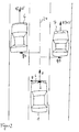
- FIG. 1 a first environment situation is shown as it may occur during the operation of the invention.
- a vehicle 1 which is also referred to as a separate vehicle having an object sensor 2, for example, for an adaptive distance and speed control.
- This own vehicle 1 moves on a road at the speed v, wherein the direction of movement points in the direction of the extended vehicle longitudinal axis 24.
- another vehicle 3 can be seen, which moves in the oncoming traffic lane at the speed v1.
- the object sensor 2 of the vehicle 1 recognizes the vehicle 3 as soon as it enters the object detection area and determines its distance to the own vehicle 1, the relative speed with respect to the own vehicle 1 and the azimuth angle at which the vehicle 3 was detected.
- the object sensor 2 has a coordinate system which has a first coordinate axis in the direction of the extended vehicle longitudinal axis 24 (v coordinate) and a second coordinate axis for q values 4 which indicates the lateral offset.
- the lateral offset q is defined such that positive q-values are defined for left-sided lateral offsets and negative q-values for right-sided lateral offsets.
- the q-axis the other way around, which alters left and right lateral offsets in their sign with respect to the q-values.
- FIG. 1 standing objects 5 shown, which are arranged in the present example objects on the edge of the vehicle. These can be, for example, guide posts, traffic signs, bridge piers, trees, crash barriers or other stationary objects on the roadside.
- the object sensor 2 also detects the objects 5 located on the roadway edge and recognizes from a comparison of the relative speed and the own vehicle speed v that these must be stationary objects. Detects now the object sensor 2 over a long period of time oncoming objects having a negative relative velocity vrel, the amount is greater than the own vehicle speed v and at the same time a left-lateral lateral offset have, it can be concluded from this to a legal transaction.
- the standing objects 5 are evaluated. From the knowledge of the speed v of the own vehicle 1 and the relative speed of the stationary objects 5, which corresponds in magnitude to the own speed of the vehicle 1, stationary objects can be recognized on both sides of the road. For these upright objects 5, the lateral transverse offset q 1, q 2 is calculated, wherein the lateral transverse offset q 1 can only be smaller than a lane width on one side of the extended vehicle longitudinal axis 24.
- standing objects 5 beyond the oncoming lane have a lateral lateral offset q2 with respect to the extended vehicle longitudinal axis 24, which is greater than a lane width.
- the average width of a roadway can be stored in the distance and speed controller as an average value and for example be between 3.4 meters and 3.8 meters.
- FIG. 2 another environment situation is presented, as it can occur especially when driving on multi-lane roads.
- the own vehicle which is equipped with an object sensor 2.
- This own vehicle moves in the present example on the middle lane of a three-lane road.
- another vehicle 6 moves, which is traveling at a speed v2 that is greater than the speed v of the vehicle 1.
- a third vehicle 7 is shown, which is operated at the speed v3, which is smaller than the speed v of the own vehicle 1.
- the vehicle 6 traveling at the speed v2 has recently passed the own vehicle 1, and the third vehicle 7 being moved at the speed v3 lower than the speed v of the own vehicle 1 will shortly become the vehicle own vehicle 1 overhauled.
- the vehicles 6, 7 are located in the object detection area of the object sensor 2, which measures their distance, their relative speed and the azimuth angle of these vehicles. Furthermore, the speed of the own vehicle 1 by the speed sensor 10 is known. From this, the absolute speeds of the vehicles 6, 7 can be calculated, as well as their lateral transverse offset q4, q5 calculated with respect to the extended vehicle longitudinal axis 24. If the object sensor 2 recognizes a vehicle which has a positive relative speed with respect to the vehicle 1, that therefore moves faster than the own vehicle 1, it is closed in the presence of a left-lateral lateral offset q4 on a right-hand traffic and closed at a right-lateral lateral cross-offset on a left-hand traffic.
- a vehicle 7 is detected by the object sensor 2, which has a negative relative speed, wherein the absolute value of the absolute velocity v3 is between zero and the speed v of the own vehicle, this is a slower vehicle, but the same direction of movement own vehicle 1 has.
- a right lateral lateral offset q5 which in the present example can also be a negative q value, is determined with respect to this vehicle 7, the recognition device concludes a right-hand traffic, but the slower vehicle has a left-lateral lateral offset q5 with respect to the extended vehicle longitudinal axis 24 on (positive q value), it is closed to a left-hand traffic.
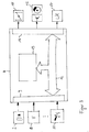
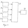
- FIG. 3 a block diagram of an embodiment of the device according to the invention is shown.
- a distance and speed control device 8 which has, inter alia, an input circuit 9.
- the distance and speed controller 8 input signals are supplied.
- These input signals originate, for example, from an object sensor 2, which can be embodied, for example, as a radar, laser, ultrasound, video sensor or a combination thereof, and represent the relative speed, the distance and the azimuth angle of the detected objects with respect to the extended vehicle longitudinal axis 24 the input circuit 9 is supplied with a speed signal from a speed sensor 10, which determines the speed of the own vehicle 1.
- an operating element 11 is provided, by means of which the distance and speed controller 8 can be switched on and off as well as being adjustable and operable.
- the quantities supplied to the input circuit 9 are supplied to a calculation device 13 by means of a data exchange device 12.
- the calculation device 13 is designed for example as a microprocessor or digital signal processor and calculates from the input variables control signals for regulating the vehicle speed and other output variables.
- the method according to the invention is provided, for example in the form of computer software which generates output signals from the input variables in the manner according to the invention.
- the of the Calculation device 13 generated output signals are supplied by means of the data exchange device 12 to an output circuit 14, which outputs, among other control signals to a power-determining actuator of an internal combustion engine 15 and the deceleration device 16 of the vehicle.
- the corresponding power control element 15 which may be, for example, an electrically controllable throttle valve, a fuel quantity metering device of a storage injection system or an electrically controllable control rod of a fuel injection pump, transmits this to a control signal To implement acceleration.
- a deceleration signal is supplied to the deceleration devices 16 of the vehicle.
- This deceleration signal can be converted into a vehicle deceleration, for example, by means of an electrically actuatable brake device, which may be, for example, an electrohydraulic brake or may be an electrically driven servo brake. It is further provided that the output circuit 14 outputs a signal to a display device 17, which tells the driver, which sense of traffic has been detected and is currently set in the distance and speed controller 8.
- the display device 17 may for example be a plain text display in the dashboard of the vehicle or include one or more indicator lights in the dashboard of the vehicle.
- Function blocks 18 to 21 represent the different detection methods for the sense of traffic. These different recognition methods can run in parallel and pass on their results to a plausibility check stage 22.
- the sense of traffic is determined in block 18, depending on the detected, oncoming, moving targets, as outlined for example by the vehicle 3, the sense of traffic is determined.
- the sense of traffic is determined as a function of the detected, stationary objects, as outlined, for example, by the roadway boundaries 5.
- the sense of traffic determines whether a right or left traffic is present or no result can be determined.
- the detected, movable, slower objects, as they are, for example, in FIG. 2 are sketched by vehicle 7, the current sense of traffic determined.
- the results obtained by the individual recognition methods in blocks 18 to 21 are sent to a plausibility checker 22 and as a result can output either left-hand traffic, right-hand traffic or no detectable result. Because many detection methods work mainly on multi-lane roads and other detection methods mainly operate on lanes that provide oncoming traffic and provide only one lane for each direction of travel, it is possible that not all methods can always give a clear result, and therefore an indeterminate one Condition, so no determinable sense of traffic can be spent.
- the plausibility check 22 checks whether the results which have resulted in either a right-hand traffic or a left-hand traffic are contradictory to one another.
- the results of the detection methods which could determine no result, are not taken into account, the results of a left or right traffic have resulted, but must all have led to a clear result, ie all results that have either left or right traffic must also at the same time have given identical result. If a right-hand traffic or a left-hand traffic is detected by this plausibility checkpoint 22, then this sense of traffic must be stably recognized over a longer period of time, ie no switch to a different sense of traffic during this time must take place. If a sense of traffic is unambiguously detected over the predetermined period of time, then this sense of traffic is transferred in block 23 to the distance and speed controller, which requires this information to set certain driving functions and control parameters.
- the display device 17 which informs the driver of the currently detected sense of traffic output. Furthermore, it can be provided that the driver has the opportunity to intervene manually and set the traffic awareness by a manual specification of the sense of traffic. This possibility ensures that the driver can override the automatic detection in the event of a misrecognized sense of traffic and can give the controller the current, correct sense of traffic.
Landscapes
- Engineering & Computer Science (AREA)
- Radar, Positioning & Navigation (AREA)
- Remote Sensing (AREA)
- Physics & Mathematics (AREA)
- General Physics & Mathematics (AREA)
- Computer Networks & Wireless Communication (AREA)
- Transportation (AREA)
- Electromagnetism (AREA)
- Mechanical Engineering (AREA)
- Chemical & Material Sciences (AREA)
- Combustion & Propulsion (AREA)
- Traffic Control Systems (AREA)
- Radar Systems Or Details Thereof (AREA)
- Control Of Driving Devices And Active Controlling Of Vehicle (AREA)
- Measurement Of Velocity Or Position Using Acoustic Or Ultrasonic Waves (AREA)
Claims (10)
- Procédé de détection automatique et d'ajustement du sens du trafic dans une régulation adaptative (8) de distance et de vitesse, en particulier pour un véhicule automobile (1),
dans lequel la vitesse relative d'objets (3, 5, 6, 7) détectés, le décalage latéral (q1, q2, q3, q4, q5) des objets détectés (3, 5, 6, 7) par rapport à l'axe longitudinal (24) du véhicule et la vitesse (v) du véhicule concerné (1) sont à amenés à la régulation adaptative (8) de distance et de vitesse, et dans lequel
en fonction des cibles mobiles (3, 18) détectées et circulant en sens inverse, on décide si le trafic est situé à gauche ou à droite en détectant un trafic à droite si les objets mobiles (3) détectés et venant en sens inverse présentent un décalage latéral (q3) du côté gauche de l'axe longitudinal (24) du véhicule et un trafic à gauche si on détecte un décalage latéral (q3) du côté droit et dans lequel
en fonction des objets fixes (5, 19) détectés, on décide si le trafic s'effectue à gauche ou à droite en détectant un trafic à droite si les objets fixes détectés (5) dont le niveau de décalage latéral (q1, q2) est inférieur à la largeur de la bande de circulation présentent un décalage latéral à droite (q1, q2) de l'axe longitudinal (24) du véhicule et un trafic à gauche si les objets fixes détectés (5) dont le niveau de décalage latéral (q1, q2) est inférieur à la largeur de la bande de circulation présentent un décalage latéral (q1, q2) à gauche de l'axe longitudinal (24) du véhicule,
caractérisé en ce que
on vérifie la plausibilité (22) des opérations de détection du trafic à droite et du trafic à gauche et on doit reconnaître en toute sécurité que la modification détectée du sens du trafic a lieu pendant une durée prédéterminée avant d'effectuer un nouveau réglage du régulateur adaptatif de distance et de vitesse ainsi que l'affichage du nouveau sens du trafic. - Procédé selon la revendication 1, caractérisé en ce que l'on détecte qu'un objet mobile (3) vient en sens inverse lorsque sa vitesse relative est négative et lorsque la valeur de la vitesse relative est supérieure à la valeur de la vitesse propre (v) du véhicule.
- Procédé selon la revendication 1, caractérisé en ce que l'on détecte qu'un objet est fixe si la valeur de sa vitesse relative correspond sensiblement à la valeur de la vitesse propre (v) du véhicule.
- Procédé selon la revendication 1, caractérisé en ce que l'on détecte que le trafic s'effectue à droite si les objets mobiles détectés (6) plus rapides présentent un décalage latéral (q4) à gauche de l'axe longitudinal (24) du véhicule et un trafic du côté gauche si les objets mobiles détectés (6) plus rapides présentent un décalage latéral (q4) à droite de l'axe longitudinal du véhicule.
- Procédé selon les revendications 1 ou 4, caractérisé en ce que l'on détecte qu'un objet mobile (6) est plus rapide si sa vitesse relative par rapport au véhicule propre (1) est positive.
- Procédé selon la revendication 1, caractérisé en ce que l'on détecte que le trafic s'effectue à droite si les objets mobiles détectés (7) plus lents présentent un décalage latéral (q5) à droite de l'axe longitudinal (24) du véhicule et on détecte que le trafic s'effectue à gauche si les objets mobiles détectés (7) plus lents présentent un décalage latéral (q5) à gauche de l'axe longitudinal (24) du véhicule.
- Procédé selon les revendications 1 ou 6, caractérisé en ce que l'on détecte qu'un objet mobile (7) est plus lent si sa vitesse relative par rapport au véhicule propre (1) est négative et si le niveau de vitesse relative est compris entre zéro et le niveau de la vitesse propre (v) du véhicule.
- Procédé selon la revendication 1, caractérisé en ce que le sens du trafic détecté à tout instant est affiché (23) au conducteur au moyen d'un dispositif d'affichage (17).
- Dispositif de détection automatique et d'ajustement du sens du trafic dans une régulation adaptative (8) de distance et de vitesse, en particulier pour un véhicule automobile (1), dans lequel des moyens (2, 10) de détermination de la vitesse relative d'objets détectés, du décalage latéral des objets détectés par rapport à l'axe longitudinal du véhicule et de la vitesse du véhicule propre sont prévus,
caractérisé en ce que
le procédé selon la revendication 1 est exécuté dans le dispositif. - Dispositif selon la revendication 9, caractérisé en ce que le moyen (2) de détermination de la vitesse relative des objets détectés et du décalage latéral des objets détectés par rapport à l'axe longitudinal (24) du véhicule est un détecteur radar, un détecteur laser, un détecteur à ultrasons, un détecteur vidéo ou une de leurs combinaisons.
Applications Claiming Priority (2)
| Application Number | Priority Date | Filing Date | Title |
|---|---|---|---|
| DE10345809A DE10345809A1 (de) | 2003-09-30 | 2003-09-30 | Verfahren und Vorrichtung zur Erkennung und Einstellung des Verkehrssinns |
| DE10345809 | 2003-09-30 |
Publications (3)
| Publication Number | Publication Date |
|---|---|
| EP1520745A2 EP1520745A2 (fr) | 2005-04-06 |
| EP1520745A3 EP1520745A3 (fr) | 2005-09-07 |
| EP1520745B1 true EP1520745B1 (fr) | 2009-03-04 |
Family
ID=34306205
Family Applications (1)
| Application Number | Title | Priority Date | Filing Date |
|---|---|---|---|
| EP04022036A Expired - Lifetime EP1520745B1 (fr) | 2003-09-30 | 2004-09-16 | Procédé et dispositif de reconnaissance et régulation de conduite à gauche ou conduite à droite |
Country Status (3)
| Country | Link |
|---|---|
| EP (1) | EP1520745B1 (fr) |
| JP (1) | JP4723220B2 (fr) |
| DE (2) | DE10345809A1 (fr) |
Families Citing this family (17)
| Publication number | Priority date | Publication date | Assignee | Title |
|---|---|---|---|---|
| JP4955246B2 (ja) * | 2005-09-29 | 2012-06-20 | アルパイン株式会社 | 車載用ナビゲーション装置 |
| JP4426535B2 (ja) | 2006-01-17 | 2010-03-03 | 本田技研工業株式会社 | 車両の周辺監視装置 |
| US7518545B2 (en) * | 2006-10-26 | 2009-04-14 | Infineon Technologies Ag | Driver assistance system |
| DE102007059083A1 (de) * | 2006-12-19 | 2008-06-26 | Adc Automotive Distance Control Systems Gmbh | Vorrichtung zur reversiblen Einstellung von Kraftfahrzeugsteuersystemen |
| GB2498223B (en) * | 2012-01-09 | 2015-08-26 | Jaguar Land Rover Ltd | Method and control unit for monitoring traffic |
| US8504233B1 (en) * | 2012-04-27 | 2013-08-06 | Google Inc. | Safely navigating on roads through maintaining safe distance from other vehicles |
| SE536656C2 (sv) | 2012-09-17 | 2014-05-06 | Scania Cv Ab | Anordning och förfarande för att automatiskt fastställa om ett fordon framdrives i vänstertrafik eller högertrafik |
| DE102015226840A1 (de) * | 2015-11-03 | 2017-05-04 | Robert Bosch Gmbh | Verfahren zum Betreiben einer Längsregelungsvorrichtung eines Kraftfahrzeugs in einem Kreisverkehr |
| DE102016009762A1 (de) * | 2016-08-11 | 2018-02-15 | Trw Automotive Gmbh | Steuerungssystem und Steuerungsverfahren zum Ermitteln einer Wahrscheinlichkeit für einen Fahrspurwechsel eines vorausfahrenden Kraftfahrzeugs |
| CN106585622A (zh) * | 2016-12-20 | 2017-04-26 | 奇瑞汽车股份有限公司 | 一种道路施工情况下自动驾驶方法和智能车 |
| KR102581766B1 (ko) * | 2018-10-08 | 2023-09-22 | 주식회사 에이치엘클레무브 | 차량 제어 장치, 차량 제어 방법 및 차량 제어 시스템 |
| CN112835008B (zh) * | 2021-01-12 | 2022-03-04 | 西安电子科技大学 | 基于姿态自适应卷积网络的高分辨距离像目标识别方法 |
| JP7655071B2 (ja) * | 2021-05-14 | 2025-04-02 | 株式会社デンソー | 車両用制御装置 |
| DE102022201200A1 (de) | 2022-02-04 | 2023-08-10 | Continental Autonomous Mobility Germany GmbH | Verfahren und System zur Bestimmung einer Verkehrsausrichtung |
| DE102022203280A1 (de) | 2022-04-01 | 2023-10-05 | Continental Autonomous Mobility Germany GmbH | Verfahren und System zur Bestimmung einer Fahrspurrichtung |
| DE102022131849A1 (de) | 2022-12-01 | 2024-06-06 | Valeo Schalter Und Sensoren Gmbh | Verfahren zum Bereitstellen einer Fahrseiteninformation |
| DE102024200467A1 (de) * | 2024-01-18 | 2025-07-24 | Volkswagen Aktiengesellschaft | Verfahren zur verbesserten Erkennung eines Verkehrssinnes eines Fahrzeugs |
Family Cites Families (5)
| Publication number | Priority date | Publication date | Assignee | Title |
|---|---|---|---|---|
| JP3160108B2 (ja) * | 1993-02-23 | 2001-04-23 | 三菱電機株式会社 | 運転支援システム |
| JP3470453B2 (ja) * | 1995-04-06 | 2003-11-25 | 株式会社デンソー | 車間距離制御装置 |
| DE19637053C2 (de) * | 1996-09-12 | 2000-03-09 | Bosch Gmbh Robert | Verfahren und Vorrichtung zur automatischen Erkennung von Rechts- oder Linksverkehr |
| DE19828160B4 (de) * | 1998-06-24 | 2008-02-14 | Volkswagen Ag | Verfahren zum automatischen Erkennen der Hauptrichtungsfahrbahn bei einer mehrspurigen Strecke |
| DE10254423A1 (de) * | 2002-11-21 | 2004-06-03 | Lucas Automotive Gmbh | System zur Beeinflussung der Geschwindigkeit eines Kraftfahrzeuges |
-
2003
- 2003-09-30 DE DE10345809A patent/DE10345809A1/de not_active Withdrawn
-
2004
- 2004-09-16 EP EP04022036A patent/EP1520745B1/fr not_active Expired - Lifetime
- 2004-09-16 DE DE502004009069T patent/DE502004009069D1/de not_active Expired - Lifetime
- 2004-09-29 JP JP2004283749A patent/JP4723220B2/ja not_active Expired - Lifetime
Also Published As
| Publication number | Publication date |
|---|---|
| EP1520745A3 (fr) | 2005-09-07 |
| DE502004009069D1 (de) | 2009-04-16 |
| EP1520745A2 (fr) | 2005-04-06 |
| JP2005104462A (ja) | 2005-04-21 |
| JP4723220B2 (ja) | 2011-07-13 |
| DE10345809A1 (de) | 2005-04-21 |
Similar Documents
| Publication | Publication Date | Title |
|---|---|---|
| EP1671196B1 (fr) | Procede et dispositif pour identifier la voie de circulation d'un vehicule | |
| EP1520745B1 (fr) | Procédé et dispositif de reconnaissance et régulation de conduite à gauche ou conduite à droite | |
| DE102018105665B4 (de) | Kollisionsverhinderungssteuerungsvorrichtung | |
| EP1292462B1 (fr) | Procede et systeme pour reguler la distance entre un vehicule de reference et un vehicule roulant devant ce dernier | |
| DE10015300B4 (de) | Verfahren und Vorrichtung zur Steuerung der Fahrgeschwindigkeit eines Fahrzeugs | |
| EP1940665B1 (fr) | Regulateur de distance et de vitesse a detection d'embouteillage | |
| EP2676857B1 (fr) | Procédé et dispositif de génération d'un paramètre de commande pour un système d'assistance de distance d'un véhicule à base d'images | |
| DE102013216994B4 (de) | Geschwindigkeitsassistent für ein Kraftfahrzeug | |
| EP1777143B1 (fr) | Dispositif d'assistance au changement de voie | |
| DE102018112238B4 (de) | Kollisionsverhinderungssteuerungsvorrichtung | |
| EP1577682B1 (fr) | Système de localisation d'objets pour véhicule automobile pour identifier des procédures de changement de voie | |
| DE10358034A1 (de) | Adaption einer automatischen Folgeführung an potentiell auf die eigene Fahrspur einscherende Verkehrsteilnehmer | |
| DE102004038734A1 (de) | Verfahren und Vorrichtung zur Auslösung einer Notbremsung | |
| DE10254424A1 (de) | System zur Beeinflussung der Geschwindigkeit eines Kraftfahrzeuges | |
| DE102011083265A1 (de) | Verfahren und Fahrerassistenzvorrichtung zur Ermittlung des Vorhandenseins einer baulichen Trennung zwischen zwei Fahrbahnen | |
| DE102022119571A1 (de) | Benachrichtigungssteuerungsvorrichtung für ein Fahrzeug | |
| DE19828160B4 (de) | Verfahren zum automatischen Erkennen der Hauptrichtungsfahrbahn bei einer mehrspurigen Strecke | |
| EP2181891A2 (fr) | Procédé et dispositif de réglage de phares de virage, notamment lors du passage de croisements ou jonctions de routes | |
| DE102020215926A1 (de) | Verfahren und Vorrichtung zur Steuerung der Geschwindigkeit eines Fahrzeugs | |
| WO2018228733A1 (fr) | Dispositif de détection pour un véhicule automatisé | |
| EP1562781A1 (fr) | Systeme permettant de reconnaitre des conditions de conduite a gauche ou conduite a droite | |
| DE102005046841A1 (de) | Verfahren und Vorrichtung zur Komposition eines Zustandsvektors mit Objektattributswerten eines Zielobjekts für die Eingabe in ein Fahrzeugkontrollsystem | |
| EP1529719B1 (fr) | Appareil de guidage de véhicule avec guidage latéral et reconaissance d'objets et procédé correspondant | |
| DE102010056248A1 (de) | Verfahren und Abstandsregelsystem zur Regelung eines Folgeabstands | |
| EP4303089B1 (fr) | Procédé et appareil de commande pour faire fonctionner une motocyclette avec un système de régulation de distance |
Legal Events
| Date | Code | Title | Description |
|---|---|---|---|
| PUAI | Public reference made under article 153(3) epc to a published international application that has entered the european phase |
Free format text: ORIGINAL CODE: 0009012 |
|
| AK | Designated contracting states |
Kind code of ref document: A2 Designated state(s): AT BE BG CH CY CZ DE DK EE ES FI FR GB GR HU IE IT LI LU MC NL PL PT RO SE SI SK TR |
|
| AX | Request for extension of the european patent |
Extension state: AL HR LT LV MK |
|
| PUAL | Search report despatched |
Free format text: ORIGINAL CODE: 0009013 |
|
| AK | Designated contracting states |
Kind code of ref document: A3 Designated state(s): AT BE BG CH CY CZ DE DK EE ES FI FR GB GR HU IE IT LI LU MC NL PL PT RO SE SI SK TR |
|
| AX | Request for extension of the european patent |
Extension state: AL HR LT LV MK |
|
| RIC1 | Information provided on ipc code assigned before grant |
Ipc: 7B 60K 31/00 A Ipc: 7G 01S 13/93 B |
|
| 17P | Request for examination filed |
Effective date: 20060307 |
|
| AKX | Designation fees paid |
Designated state(s): DE FR GB SE |
|
| GRAP | Despatch of communication of intention to grant a patent |
Free format text: ORIGINAL CODE: EPIDOSNIGR1 |
|
| GRAS | Grant fee paid |
Free format text: ORIGINAL CODE: EPIDOSNIGR3 |
|
| GRAA | (expected) grant |
Free format text: ORIGINAL CODE: 0009210 |
|
| AK | Designated contracting states |
Kind code of ref document: B1 Designated state(s): DE FR GB SE |
|
| REG | Reference to a national code |
Ref country code: GB Ref legal event code: FG4D Free format text: NOT ENGLISH |
|
| REF | Corresponds to: |
Ref document number: 502004009069 Country of ref document: DE Date of ref document: 20090416 Kind code of ref document: P |
|
| PG25 | Lapsed in a contracting state [announced via postgrant information from national office to epo] |
Ref country code: SE Free format text: LAPSE BECAUSE OF FAILURE TO SUBMIT A TRANSLATION OF THE DESCRIPTION OR TO PAY THE FEE WITHIN THE PRESCRIBED TIME-LIMIT Effective date: 20090604 |
|
| PLBE | No opposition filed within time limit |
Free format text: ORIGINAL CODE: 0009261 |
|
| STAA | Information on the status of an ep patent application or granted ep patent |
Free format text: STATUS: NO OPPOSITION FILED WITHIN TIME LIMIT |
|
| 26N | No opposition filed |
Effective date: 20091207 |
|
| REG | Reference to a national code |
Ref country code: FR Ref legal event code: PLFP Year of fee payment: 13 |
|
| REG | Reference to a national code |
Ref country code: FR Ref legal event code: PLFP Year of fee payment: 14 |
|
| REG | Reference to a national code |
Ref country code: FR Ref legal event code: PLFP Year of fee payment: 15 |
|
| PGFP | Annual fee paid to national office [announced via postgrant information from national office to epo] |
Ref country code: GB Payment date: 20200923 Year of fee payment: 17 Ref country code: FR Payment date: 20200921 Year of fee payment: 17 |
|
| GBPC | Gb: european patent ceased through non-payment of renewal fee |
Effective date: 20210916 |
|
| PG25 | Lapsed in a contracting state [announced via postgrant information from national office to epo] |
Ref country code: GB Free format text: LAPSE BECAUSE OF NON-PAYMENT OF DUE FEES Effective date: 20210916 Ref country code: FR Free format text: LAPSE BECAUSE OF NON-PAYMENT OF DUE FEES Effective date: 20210930 |
|
| PGFP | Annual fee paid to national office [announced via postgrant information from national office to epo] |
Ref country code: DE Payment date: 20231124 Year of fee payment: 20 |
|
| REG | Reference to a national code |
Ref country code: DE Ref legal event code: R071 Ref document number: 502004009069 Country of ref document: DE |