EP1671196B1 - Procede et dispositif pour identifier la voie de circulation d'un vehicule - Google Patents
Procede et dispositif pour identifier la voie de circulation d'un vehicule Download PDFInfo
- Publication number
- EP1671196B1 EP1671196B1 EP04786786A EP04786786A EP1671196B1 EP 1671196 B1 EP1671196 B1 EP 1671196B1 EP 04786786 A EP04786786 A EP 04786786A EP 04786786 A EP04786786 A EP 04786786A EP 1671196 B1 EP1671196 B1 EP 1671196B1
- Authority
- EP
- European Patent Office
- Prior art keywords
- vehicle
- detected
- objects
- lane
- velocity
- Prior art date
- Legal status (The legal status is an assumption and is not a legal conclusion. Google has not performed a legal analysis and makes no representation as to the accuracy of the status listed.)
- Expired - Lifetime
Links
Images


Classifications
-
- B—PERFORMING OPERATIONS; TRANSPORTING
- B60—VEHICLES IN GENERAL
- B60W—CONJOINT CONTROL OF VEHICLE SUB-UNITS OF DIFFERENT TYPE OR DIFFERENT FUNCTION; CONTROL SYSTEMS SPECIALLY ADAPTED FOR HYBRID VEHICLES; ROAD VEHICLE DRIVE CONTROL SYSTEMS FOR PURPOSES NOT RELATED TO THE CONTROL OF A PARTICULAR SUB-UNIT
- B60W30/00—Purposes of road vehicle drive control systems not related to the control of a particular sub-unit, e.g. of systems using conjoint control of vehicle sub-units
- B60W30/14—Adaptive cruise control
- B60W30/16—Control of distance between vehicles, e.g. keeping a distance to preceding vehicle
-
- B—PERFORMING OPERATIONS; TRANSPORTING
- B60—VEHICLES IN GENERAL
- B60W—CONJOINT CONTROL OF VEHICLE SUB-UNITS OF DIFFERENT TYPE OR DIFFERENT FUNCTION; CONTROL SYSTEMS SPECIALLY ADAPTED FOR HYBRID VEHICLES; ROAD VEHICLE DRIVE CONTROL SYSTEMS FOR PURPOSES NOT RELATED TO THE CONTROL OF A PARTICULAR SUB-UNIT
- B60W30/00—Purposes of road vehicle drive control systems not related to the control of a particular sub-unit, e.g. of systems using conjoint control of vehicle sub-units
- B60W30/14—Adaptive cruise control
- B60W30/143—Speed control
-
- B—PERFORMING OPERATIONS; TRANSPORTING
- B60—VEHICLES IN GENERAL
- B60W—CONJOINT CONTROL OF VEHICLE SUB-UNITS OF DIFFERENT TYPE OR DIFFERENT FUNCTION; CONTROL SYSTEMS SPECIALLY ADAPTED FOR HYBRID VEHICLES; ROAD VEHICLE DRIVE CONTROL SYSTEMS FOR PURPOSES NOT RELATED TO THE CONTROL OF A PARTICULAR SUB-UNIT
- B60W2520/00—Input parameters relating to overall vehicle dynamics
- B60W2520/10—Longitudinal speed
-
- B—PERFORMING OPERATIONS; TRANSPORTING
- B60—VEHICLES IN GENERAL
- B60W—CONJOINT CONTROL OF VEHICLE SUB-UNITS OF DIFFERENT TYPE OR DIFFERENT FUNCTION; CONTROL SYSTEMS SPECIALLY ADAPTED FOR HYBRID VEHICLES; ROAD VEHICLE DRIVE CONTROL SYSTEMS FOR PURPOSES NOT RELATED TO THE CONTROL OF A PARTICULAR SUB-UNIT
- B60W2552/00—Input parameters relating to infrastructure
- B60W2552/05—Type of road, e.g. motorways, local streets, paved or unpaved roads
-
- B—PERFORMING OPERATIONS; TRANSPORTING
- B60—VEHICLES IN GENERAL
- B60W—CONJOINT CONTROL OF VEHICLE SUB-UNITS OF DIFFERENT TYPE OR DIFFERENT FUNCTION; CONTROL SYSTEMS SPECIALLY ADAPTED FOR HYBRID VEHICLES; ROAD VEHICLE DRIVE CONTROL SYSTEMS FOR PURPOSES NOT RELATED TO THE CONTROL OF A PARTICULAR SUB-UNIT
- B60W2552/00—Input parameters relating to infrastructure
- B60W2552/10—Number of lanes
-
- B—PERFORMING OPERATIONS; TRANSPORTING
- B60—VEHICLES IN GENERAL
- B60W—CONJOINT CONTROL OF VEHICLE SUB-UNITS OF DIFFERENT TYPE OR DIFFERENT FUNCTION; CONTROL SYSTEMS SPECIALLY ADAPTED FOR HYBRID VEHICLES; ROAD VEHICLE DRIVE CONTROL SYSTEMS FOR PURPOSES NOT RELATED TO THE CONTROL OF A PARTICULAR SUB-UNIT
- B60W2554/00—Input parameters relating to objects
- B60W2554/40—Dynamic objects, e.g. animals, windblown objects
- B60W2554/404—Characteristics
- B60W2554/4041—Position
-
- B—PERFORMING OPERATIONS; TRANSPORTING
- B60—VEHICLES IN GENERAL
- B60W—CONJOINT CONTROL OF VEHICLE SUB-UNITS OF DIFFERENT TYPE OR DIFFERENT FUNCTION; CONTROL SYSTEMS SPECIALLY ADAPTED FOR HYBRID VEHICLES; ROAD VEHICLE DRIVE CONTROL SYSTEMS FOR PURPOSES NOT RELATED TO THE CONTROL OF A PARTICULAR SUB-UNIT
- B60W2554/00—Input parameters relating to objects
- B60W2554/80—Spatial relation or speed relative to objects
- B60W2554/801—Lateral distance
-
- G—PHYSICS
- G08—SIGNALLING
- G08G—TRAFFIC CONTROL SYSTEMS
- G08G1/00—Traffic control systems for road vehicles
- G08G1/16—Anti-collision systems
- G08G1/166—Anti-collision systems for active traffic, e.g. moving vehicles, pedestrians, bikes
-
- G—PHYSICS
- G08—SIGNALLING
- G08G—TRAFFIC CONTROL SYSTEMS
- G08G1/00—Traffic control systems for road vehicles
- G08G1/16—Anti-collision systems
- G08G1/167—Driving aids for lane monitoring, lane changing, e.g. blind spot detection
Definitions
- the present invention relates to a method and apparatus for lane detection for a vehicle equipped with an adaptive distance and speed control, wherein the adaptive distance and speed controller by means of an object detection system, the relative speed of detected objects, the lateral displacement of the detected objects with respect to the vehicle longitudinal axis and the speed of your own vehicle is supplied. From the relative speed of the objects and the vehicle's own speed is determined whether it is an oncoming, stationary or in the same direction as the own vehicle, moving object. In conjunction with the calculated lateral lateral offset of the object relative to the vehicle longitudinal axis, the number of available lanes and the lane currently being traveled by the driver's own vehicle are determined.
- preceding vehicle is the Speed of the own vehicle is regulated in the sense of a constant distance control and in the absence of a preceding vehicle, the speed of the own vehicle in terms of a constant speed control is set to a predetermined speed by the driver.
- a model-based lane assignment for vehicles is known in which a lane assignment of successive vehicles is made, the lane assignment is modeled on a frequency distribution of the transverse offsets of detected radar objects.
- this method can be used for maladjustment detection of the sensor.
- the US 2001/025211 A1 also discloses a method for lane detection for a vehicle with adaptive distance and speed control, in which it is determined on the basis of the relative speeds, whether it is standing, with moving or oncoming objects.
- the core and advantages of the invention The core of the present invention is to provide a method and a device which make it possible, by means of the data of an object detection system, to detect the distance, the azimuth angle and the relative speed of detected objects as well as the own vehicle speed and in dependence of these data indicate the number of existing lanes of the currently traveled road and the currently traveled lane on the road. According to the invention this is achieved by the features of the independent claims. Advantageous developments and refinements emerge from the subclaims.
- a drive on a single-lane road is detected when objects are detected which have a negative relative speed which is greater in absolute value than the vehicle's own speed and which have a left-lateral lateral offset that is smaller in magnitude than a predetermined lane width value is, and / or objects are detected, which have a negative relative speed, the amount of which corresponds approximately to the own vehicle speed and which have a right lateral lateral offset, the amount is smaller than a predetermined lane width value, and / or objects are detected, the one Have negative relative speed, the amount of about the own Vehicle speed corresponds and have a left-side, lateral transverse offset, the amount is greater than a predetermined lane width value.
- the use of the left lane of a multi-lane road is detected when objects are detected which have a negative relative speed, the amount of which corresponds approximately to the own vehicle speed and which have a left lateral offset, the amount is smaller than a predetermined lane width value is and / or objects are detected, which have either a positive relative speed or a negative relative speed, the amount is approximately between zero and the vehicle's own speed, and have a right-lateral lateral offset.
- a middle lane of a multi-lane road it is advantageous for the use of a middle lane of a multi-lane road to be detected when objects are detected which have a negative relative speed which corresponds in magnitude to the vehicle's own speed and which have any lateral lateral offset that is greater in magnitude than one is predetermined lane width value and or or objects are detected, which have either a positive relative speed or a negative relative speed, the amount is approximately between zero and the vehicle's own speed, and have a magnitude arbitrary, lateral transverse offset.
- the use of the right-hand lane of a multi-lane road is detected when objects are detected which have a negative relative speed, the amount of which corresponds approximately to the own vehicle speed and which have a right-hand, lateral transverse offset, the amount is smaller than a predetermined lane width value and / or objects are detected, either a positive Relative speed or a negative relative speed, the amount is approximately between zero and the own vehicle speed, have, and have a left-lateral lateral offset.
- the part of the field of view of the object detection system in which the detected objects can be taken into account for regulation is extended to larger, right-sided, lateral transverse offsets.
- the determined number of lanes and the detection of the currently traveled lane only becomes effective if the determined result remains unchanged over a predetermined period of time.
- the predetermined lane width value is between 3.4 meters and 3.8 meters.
- the object detection system it is advantageous for the object detection system to have a radar sensor, a laser sensor, an ultrasound sensor, a video sensor or a combination thereof.
- control element which is provided for a control unit of an adaptive distance or speed control of a motor vehicle.
- a program is stored on the control, which is executable on a computing device, in particular on a microprocessor or signal processor, and suitable for carrying out the method according to the invention.
- the invention is realized by a program stored on the control program, so that this provided with the program control in the same way represents the invention, as the method to whose execution the program is suitable.
- an electrical storage medium can be used as the control, for example a read-only memory.
- the relative speed Vrel of the detected object determined by the object detection system 2 is defined in the context of the present invention such that there is a negative relative speed when it is an oncoming vehicle or is an object moving in the same direction as the own vehicle 1 However, it has a lower speed than your own vehicle.
- positive relative velocities are defined as being moving objects moving in the same direction as the own vehicle 1, but at a higher speed, so that they move away from the own vehicle 1.
- objects with negative relative speed are objects which are relatively related to the own vehicle and move towards it, and thus are either oncoming vehicles or vehicles moving in the same direction as the own vehicle, but at a lower absolute speed than your own vehicle.
- FIG. 1 shows a road in which a lane is provided for each direction of travel.
- the own vehicle 1 can be recognized, which has an object detection system 2.
- This object detection system 2 which may be designed as a radar, laser, ultrasound or video sensor or as a combination thereof, determines the distance, the relative speed and the azimuth angle of detected objects with respect to the own vehicle 1.
- This determined data is an adaptive distance and Speed controller supplied which controls the vehicle 1 as a function of the detected measured values. From the knowledge of the relative speed of detected objects as well as the own vehicle speed, the absolute velocity of the detected objects can be determined. Furthermore, it is possible to determine from the azimuth angle, under which the object is detected, as well as the distance of the object, the so-called lateral transverse offset.
- the lateral transverse offset is the smallest distance that the detected object to the vehicle longitudinal axis 3 has.
- This lateral transverse offset can furthermore be subdivided into right-sided and left-lateral lateral transverse offsets, wherein the vehicle longitudinal axis 3, which is viewed in the direction of movement of the own vehicle 1, can be referred to on the right-side or left-side.
- the object detection system 2 with a coordinate system which, for example, has a first axis v, which is aligned parallel to the vehicle longitudinal axis 3, and an axis q arranged orthogonally thereto for the lateral transverse offset, for example the left lateral, in FIG Transverse offsets as positive q-values and right-sided, lateral transverse offsets as negative q-values.
- a coordinate system which, for example, has a first axis v, which is aligned parallel to the vehicle longitudinal axis 3, and an axis q arranged orthogonally thereto for the lateral transverse offset, for example the left lateral, in FIG Transverse offsets as positive q-values and right-sided, lateral transverse offsets as negative q-values.
- the transverse offset axis q the other way around, so that right-side transverse offsets describe positive q values and left-side transverse offsets describe negative q values.
- the absolute velocity V1 of the oncoming vehicle 4 is determined from the relative velocity Vrel measured for this purpose and the own vehicle speed V.
- the lateral transverse offset q1 for the vehicle 4 is determined from the measured distance of the oncoming vehicle 4 and the azimuth angle.
- standing objects 5 which are also detected as objects, for example, at the edge of the road, such as crash barriers, roadway boundaries in the form of delineators, traffic signs or, for example, bridge piers.
- Standing objects are recognized in particular by the fact that the amount of the relative speed of the stationary objects corresponds approximately to the own vehicle speed V of the own vehicle 1. Furthermore, a left-sided or right-sided, lateral transverse offset q2 or q3 is also determined for stationary objects. If, for example, an object 4 is detected which has a negative relative speed Vrel which is greater in magnitude than its own vehicle speed V, then the absolute speed V1 can be determined therefrom, which is arranged counter to its own vehicle direction V. If, furthermore, a left-lateral lateral offset q1 is determined for the detected object 4 which is smaller in magnitude than a predetermined traffic-track width value fsb, this can be used to detect a journey on a single-lane road, as shown by way of example in FIG.
- the predetermined lane width value here is a fixed value that represents approximately the width of a lane. This can for example be between 3.4 m and 3.8 m. As a result, road widths are covered, as they are common, for example, on well-developed highways or highways. If objects 5 are detected which have a negative relative speed Vrel which corresponds in magnitude to the vehicle's own speed, then these objects 5 are recognized as stationary objects. If these objects continue to have a right-lateral lateral offset q3 which is smaller in magnitude than a predetermined lane width value fsb, these are stationary Objects on the right side of the road.
- objects 5 are detected which have a negative relative speed Vrel which corresponds approximately to their own vehicle speed V in terms of magnitude and which have a left-lateral lateral offset q2 which is greater in magnitude than a predetermined lane width value fsb, these are stationary objects on the left kerbside. If such stationary objects on the left or right lane edge are detected, which have the predetermined lateral transverse offsets, then the travel on a single-lane road can likewise be detected.
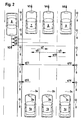
- FIG. 2 shows, by way of example, the journey on a multi-lane road.
- the driving of the own vehicle 1a in the left lane of a multi-lane road the drive of the own vehicle 1b on the middle lane of a multi-lane road and the drive of the own vehicle 1c on the right lane of a multi-lane road.
- vehicles 1a, 1b, 1c are respectively recorded, each having an object detection system 2a, 2b, 2c.
- a vehicle longitudinal axis 3a, 3b, 3c is drawn for each of these driving situations.
- standing objects 5 are shown at the edges of the road, it is not absolutely necessary that such stationary objects are provided.
- an oncoming vehicle 6 is shown by way of example, which moves on the opposite direction of travel lane with the speed V2.
- three preceding vehicles 7, 8, 9 are shown by way of example on the left, middle and right lanes, respectively, which move with the speeds V3, V4, V5. If during the operation according to the invention, for example, an object 6 is detected which has a negative relative speed Vrel which is greater in terms of magnitude than its own vehicle speed V, this is an oncoming vehicle.
- a left-lateral lateral offset q4, q5, q6 is found for this oncoming vehicle which is greater in magnitude than a predetermined lane width value fsb, it can be concluded that the vehicle 1 is on a multi-lane road on the left, middle or right lane, that is in the situation 1a, 1b or 1c.
- an object is detected by the object detection system 2, which has a negative relative speed Vrel which corresponds in magnitude to approximately its own vehicle speed V, ie it is a stationary object and the object has any lateral offset q11, q12 which is greater in magnitude , as a predetermined lane width value fsb, it can be concluded that the own vehicle 1b is on the middle lane of a multi-lane road. If, furthermore, an object is detected which has either a positive relative speed Vrel or which has a negative relative speed Vrel which lies approximately between zero and its own vehicle speed V and furthermore has an arbitrary lateral transverse offset, then it can likewise be concluded that the own vehicle 1b moves on the middle lane of a multi-lane road.
- an object which has either a positive relative speed Vrel, or which has a negative relative speed Vrel, which amounts to approximately between zero and the own vehicle speed V, that is to say a preceding faster or slower vehicle and this object simultaneously has a left-lateral lateral offset q10, it can be concluded that the vehicle 1 moves in the right lane of a multi-lane road.
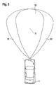
- the own vehicle 1 is shown, which is equipped on the front with an object detection system 2.
- the object detection system 2 in this case has a sensor vision area 10, which can detect moving or stationary objects ahead, the sensor sight area 10 usually being aligned symmetrically with respect to the vehicle longitudinal axis 3.
- the area in which objects can be detected by the object detection system 2 is greater than the field of view of the sensor system.
- the vision area is to be understood in the context of this invention in that only the detected objects that lie within the viewing area are evaluated and used with respect to the adaptive distance and speed control. Objects outside of the field of view, but within the transmission and reception range of the sensor, can therefore also be present, but since they are outside the defined field of view, they are not evaluated for the control of the distance and speed of the own vehicle 1.
- a right-sided, expanded viewing area 12 of the object detection system 2 is also defined.
- the extension of the part of the field of view of the object detection system in which the detected objects can be taken into account for the regulation can be covered, for example, by a very broad transmission and reception range of the detection system and only the consideration of the objects present in the extended viewing areas can be activated.
- the field of view 10 is extended to larger, right-lateral lateral displacements q by the right-side , extended viewing area 12 is activated and the left-hand, extended viewing area 11 is deactivated.
- FIG. 4 shows a block diagram of an embodiment of the device according to the invention.
- the distance and speed controller 13 which has, inter alia, an input circuit 14.
- input variables are supplied to the adaptive distance and speed controller.
- These input quantities come, for example, from an object detection system 2, which can be implemented as a radar, laser, ultrasound, video system or a combination thereof.
- This object detection system 2 is mounted on the vehicle front and has a sensor vision range according to FIG. 3.
- This object detection system 2 recognizes objects and determines their distance to the own vehicle 1, the relative speed Vrel of the object with respect to the own vehicle 1 and the azimuth angle, below which the object with respect to the vehicle longitudinal axis 3 has been detected.
- the input circuit 14th supplied quantities, the adaptive distance and speed controller can calculate the absolute speed of the detected objects and their lateral lateral offset q. Furthermore, the input circuit 14 is supplied with the speed V of the own vehicle 1 by means of a speed sensor 15. The knowledge of one's own vehicle speed V is important for the controller since its absolute speed can only be calculated from the relative speed Vrel of the detected object in conjunction with its own vehicle speed. In addition, it is possible to supply the input circuit 14 with further signals, for example signals from an operating device 16, by means of which the adaptive distance and speed controller 13 can be switched on and off, as well as system settings can be changed and made. The signals supplied to the input circuit 14 are supplied to a calculation device 18 by means of a data exchange device 17.
- manipulated variables are calculated from the input signals, which can be output to downstream adjusting elements 20, 21, 22. Further, the calculating means 18 determines from the signals supplied by the input circuit 14 whether the own vehicle 1 is currently moving on a one-lane road on a multi-lane road, and in the latter case on which lane of the multi-lane road the own vehicle 1 is currently emotional.
- the control signals determined by the calculation device 18 are forwarded by means of the data exchange device 17 to an output circuit 19.
- the output circuit 19 outputs, for example, an acceleration signal to a power-determining actuator 20 of a drive device. This may be, for example, an electrically controllable throttle valve of an internal combustion engine or a fuel quantity metering device of a storage injection system or a control rod of an injection pump.
- an acceleration request signal is output.
- the delay devices 21 may be, for example, an electrically controllable, hydraulic brake system or a act directly electrically controllable brake system of a motor vehicle.
- an adjustment signal for the field of view of the object detection system 2 is output via the output circuit 19.
- the calculation device 18 has detected a driving situation as a function of the input signals supplied to it, in which the left, extended viewing area 11 or the right, extended viewing area 12 or both extended viewing areas are to be activated, an adjusting signal is transmitted to the adjusting device for the vehicle by means of the output circuit 19 Viewing range 22 output that changes the object detection sensor 2 according to the embodiments in Figure 3.
- the extended left viewing area 11 or the extended right viewing area 12 or both extended viewing areas can be deactivated in accordance with the driving situation detected by the calculating device 18 as a function of the input signals fed to it.
Landscapes
- Engineering & Computer Science (AREA)
- Automation & Control Theory (AREA)
- Transportation (AREA)
- Mechanical Engineering (AREA)
- Traffic Control Systems (AREA)
Claims (13)
- Procédé de détection de voie de circulation pour un véhicule équipé d'une régulation adaptative de distance et de vitesse (12) selon lequel, un système de détection d'objets (2), fournit au régulateur adaptatif de distance et de vitesse (12) à l'aide la vitesse relative (vrel) des objets détectés, le déport transversal latéral (q) des objets détectés par rapport à l'axe longitudinal (3, 3a, 3b, 3c) du véhicule et la vitesse (v) du propre véhicule, et
à partir de la vitesse relative des objets (vrel) et de la vitesse propre du véhicule (v), on détermine s'il s'agit d'un objet (5, 6, 7, 8) venant en sens inverse, immobile ou se déplaçant dans la même direction que le propre véhicule,
caractérisé en ce qu'
en liaison avec le déport transversal latéral (q) calculé, de l'objet par rapport à l'axe longitudinal du véhicule (3, 3a, 3b, 3c), on détermine le nombre de voies de circulation existantes et la voie de circulation empreintée momentanément par le propre véhicule, et
on modifie la plage de détection (9, 10, 11) du système de détection d'objets (2) en fonction de la voie de circulation reconnue. - Procédé selon la revendication 1,
caractérisé en ce que
pour une circulation à droite, on reconnaît le déplacement sur une chaussée à une seule voie si,- on détecte des objets (4) ayant une vitesse relative (vrel) dont l'amplitude est supérieure à la vitesse propre (v) du véhicule et qui ont un déport transversal latéral (q) du côté gauche, dont l'amplitude est inférieure à une valeur prédéfinie de largeur de voie (fsb), et/ou- on détecte des objets (5) qui ont une vitesse relative négative (vrel) dont l'amplitude correspond sensiblement à celle de la propre vitesse (v) du véhicule et qui ont un déport transversal, latéral (q) du côté droit, dont l'amplitude est inférieure à la valeur prédéfinie de la largeur de voie de circulation (fsb), et/ou- on détecte des objets (5) ayant une vitesse relative négative (vrel) dont l'amplitude correspond sensiblement à la propre vitesse (v) du véhicule et ayant un déport transversal (q), latéral du côté gauche dont l'amplitude est supérieure à une largeur de voie de circulation, prédéfinie (fsb). - Procédé selon l'une quelconque des revendications 1 ou 2,
caractérisé en ce qu'
en cas de circulation à droite, on reconnaît une circulation sur une chaussée à plusieurs voies si,- on détecte des objets (6) ayant une vitesse relative négative dont l'amplitude est supérieure à la propre vitesse de circulation du véhicule et qui ont un déport transversal latéral côté gauche (q) dont l'amplitude est supérieure à une largeur prédéfinie de voie de circulation (fsb). - Procédé selon l'une quelconque des revendications précédentes,
caractérisé en ce qu'
en cas de circulation à droite, on reconnaît l'utilisation de la voie de circulation gauche d'une chaussée à plusieurs voies (la) si,- on détecte des objets (5) ayant une vitesse relative négative (vrel) dont l'amplitude correspond sensiblement à celle de la vitesse propre du véhicule (v) et qui ont un déport transversal latéral (q) côté gauche dont l'amplitude est inférieure à une valeur prédéfinie de largeur de voie (fsb), et/ou- on détecte des objets (7, 8, 9) qui ont soit une vitesse relative positive (vrel) soit une vitesse relative négative (vrel) dont l'amplitude est comprise entre environ zéro et la propre vitesse du véhicule (v) et qui ont un déport transversal (q), latéral, du côté droit. - Procédé selon l'une quelconque des revendications précédentes,
caractérisé en ce qu'
en cas de circulation à droite, on reconnaît l'utilisation d'une voie de circulation médiane d'une chaussée à plusieurs voies (1b) si,- on détecte des objets (5) qui ont une vitesse relative négative dont l'amplitude correspond sensiblement à celle de la vitesse propre du véhicule et qui ont un déport transversal latéral (q) quelconque dont l'amplitude est supérieure à une largeur de voie de circulation (fsb) prédéfinie, et/ou- on détecte des objets (7, 8, 9) qui ont soit une vitesse relative positive (vrel) soit une vitesse relative négative (vrel) dont l'amplitude est comprise entre environ zéro et la vitesse propre du véhicule (v) et qui ont un décalage transversal (q), latéral, quelconque. - Procédé selon l'une quelconque des revendications précédentes,
caractérisé en ce qu'
en cas de circulation à droite, on reconnaît l'utilisation de la voie de circulation droite sur une chaussée à plusieurs voies (1c) si,- on détecte des objets (5) ayant une vitesse relative négative (vrel) dont l'amplitude correspond sensiblement à celle de la vitesse propre du véhicule (v) et qui ont un déport transversal latéral (q) du côté droit dont l'amplitude est inférieure à une largeur de voie de circulation (fsb) prédéfinie, et/ou- on détecte des objets (7, 8, 9) qui ont soit une vitesse relative positive (vrel) soit une vitesse relative négative (vrel) dont l'amplitude est comprise entre sensiblement zéro et la propre vitesse du véhicule (v) et qui ont un déport transversal (q), latéral, du côté gauche. - Procédé selon l'une quelconque des revendications précédentes,
caractérisé en ce que
si on reconnaît une circulation sur une chaussée à une voie, la partie de la plage de visibilité (10) du système de détection d'objets (2) dans laquelle on doit tenir compte des objets reconnus pour la régulation, est étendue pour des déports transversaux (q), latéraux plus grands du côté gauche (11) et du côté droit (12). - Procédé selon l'une quelconque des revendications précédentes,
caractérisé en ce que
si l'on reconnaît l'utilisation de la voie de circulation gauche d'une chaussée à plusieurs voies, on étend la partie de la plage de visibilité (10) du système de détection d'objets (2) dans laquelle on peut tenir compte des objets reconnus pour la régulation, en l'étendant à des déports transversaux (q), latéraux plus grands du côté gauche (11). - Procédé selon l'une quelconque des revendications précédentes,
caractérisé en ce que
si l'on a reconnu l'utilisation de la voie de circulation droite d'une chaussée à plusieurs voies, on étend la partie de la plage de visibilité (10) du système de détection d'objets (2) dans laquelle les objets reconnus sont pris en compte pour la régulation, en étendant à des déports transversaux latéraux plus grands du côté droit (12). - Procédé selon l'une quelconque des revendications précédentes,
caractérisé en ce que
le nombre déterminé de voies de circulation et la reconnaissance de la voie de circulation utilisée instantanément ne deviennent actifs que si le résultat obtenu reste inchangé pendant une durée prédéfinie (t). - Procédé selon l'une quelconque des revendications précédentes,
caractérisé en ce que
la valeur prédéfinie de la largeur de voie de circulation (fsb) est comprise entre 3,4 mètres et 3,8 mètres. - Dispositif de détection de voie de circulation et d'association de voie de circulation pour un véhicule équipé d'une régulation adaptative de distance et de vitesse (12),
le régulateur adaptatif de distance et de vitesse (12) recevant par un système de détection d'objets (2), la vitesse relative (vrel) des objets détectés, le déport transversal latéral (q) des objets détectés (4, 5, 6, 7, 8, 9) par rapport à l'axe longitudinal du véhicule (3, 3a, 3b, 3c) et la vitesse (v) du véhicule propre,
caractérisé en ce que
le dispositif est destiné à la mise en oeuvre du procédé selon la revendication 1. - Dispositif selon la revendication 12,
caractérisé en ce que
le système de détection d'objets (2) est un capteur radar, un capteur laser, un capteur à ultrasons, un capteur vidéo ou une combinaison de tels capteurs.
Applications Claiming Priority (2)
| Application Number | Priority Date | Filing Date | Title |
|---|---|---|---|
| DE10345802A DE10345802A1 (de) | 2003-09-30 | 2003-09-30 | Verfahren und Vorrichtung zur Fahrspurerkennung für ein Fahrzeug |
| PCT/DE2004/002067 WO2005040950A1 (fr) | 2003-09-30 | 2004-09-16 | Procede et dispositif pour identifier la voie de circulation d'un vehicule |
Publications (2)
| Publication Number | Publication Date |
|---|---|
| EP1671196A1 EP1671196A1 (fr) | 2006-06-21 |
| EP1671196B1 true EP1671196B1 (fr) | 2007-01-10 |
Family
ID=34306201
Family Applications (1)
| Application Number | Title | Priority Date | Filing Date |
|---|---|---|---|
| EP04786786A Expired - Lifetime EP1671196B1 (fr) | 2003-09-30 | 2004-09-16 | Procede et dispositif pour identifier la voie de circulation d'un vehicule |
Country Status (4)
| Country | Link |
|---|---|
| US (1) | US7801659B2 (fr) |
| EP (1) | EP1671196B1 (fr) |
| DE (2) | DE10345802A1 (fr) |
| WO (1) | WO2005040950A1 (fr) |
Families Citing this family (33)
| Publication number | Priority date | Publication date | Assignee | Title |
|---|---|---|---|---|
| DE102004040143A1 (de) * | 2004-08-19 | 2006-02-23 | Robert Bosch Gmbh | Verfahren und Vorrichtung zur Fahrerinformation |
| DE102005039103A1 (de) * | 2005-08-18 | 2007-03-01 | Robert Bosch Gmbh | Verfahren für die Erfassung eines Verkehrsraums |
| DE102006027326B4 (de) * | 2006-06-13 | 2026-01-22 | Robert Bosch Gmbh | Spurwechselassistent für Kraftfahrzeuge |
| DE102006054220A1 (de) * | 2006-11-15 | 2008-05-21 | Robert Bosch Gmbh | Verfahren und Vorrichtung zur Regelung der Geschwindigkeit eines Kraftfahrzeugs |
| DE102007013685A1 (de) | 2007-03-22 | 2008-09-25 | Robert Bosch Gmbh | Kollisionswarnvorrichtung für Kraftfahrzeuge |
| US8855848B2 (en) * | 2007-06-05 | 2014-10-07 | GM Global Technology Operations LLC | Radar, lidar and camera enhanced methods for vehicle dynamics estimation |
| JP4506790B2 (ja) * | 2007-07-05 | 2010-07-21 | アイシン・エィ・ダブリュ株式会社 | 道路情報生成装置、道路情報生成方法および道路情報生成プログラム |
| DE102007041727B4 (de) * | 2007-09-04 | 2021-09-23 | Adc Automotive Distance Control Systems Gmbh | Verfahren zur Spurzahlbestimmung |
| WO2009071106A1 (fr) * | 2007-12-05 | 2009-06-11 | MAX-PLANCK-Gesellschaft zur Förderung der Wissenschaften e.V. | Procédé d'analyse d'image, système d'analyse d'image et leurs utilisations |
| FR2947223B1 (fr) * | 2009-06-29 | 2015-05-01 | Valeo Vision | Procede de commande de faisceau d'eclairage pour vehicules |
| DE102010042361A1 (de) | 2010-10-13 | 2012-04-19 | Robert Bosch Gmbh | Fahrassistenzsystem in einem Kraftfahrzeug |
| FR2986646B1 (fr) | 2012-02-03 | 2016-07-01 | Renault Sas | Procede de determination du positionnement d'un vehicule dans un couloir de circulation d'une voie, et methodes de detection d'alignement et de risque de collision entre deux vehicules |
| DE102012008780B4 (de) | 2012-04-28 | 2024-07-25 | Volkswagen Aktiengesellschaft | Verfahren und Einrichtung zur Erfassung wenigstens eines Fahrbahnrandes und Kraftfahrzeug |
| DE102012208740A1 (de) | 2012-05-24 | 2013-11-28 | Bayerische Motoren Werke Aktiengesellschaft | Erkennung von Richtungsfahrbahnen |
| US9026356B2 (en) * | 2013-02-22 | 2015-05-05 | Nissan North America, Inc. | Vehicle navigation system and method |
| US9085236B2 (en) * | 2013-05-09 | 2015-07-21 | Robert Bosch Gmbh | Adaptive cruise control with stationary object recognition |
| JP5870985B2 (ja) * | 2013-10-23 | 2016-03-01 | トヨタ自動車株式会社 | 運転支援装置 |
| JP6386794B2 (ja) * | 2014-06-04 | 2018-09-05 | 日立建機株式会社 | 運搬車両 |
| DE102015001386A1 (de) * | 2015-02-04 | 2016-08-04 | Audi Ag | Verfahren zur Ermittlung einer Querpositionsinformantion eines Kraftfahrzeugs auf einer Fahrbahn und Kraftfahrzeug |
| DE102015002155A1 (de) * | 2015-02-18 | 2016-08-18 | Audi Ag | Verfahren zur Ermittlung einer Ortsinformation eines Kraftfahrzeugs bezüglich eines Fahrkorridors und Kraftfahrzeug |
| JP6520203B2 (ja) * | 2015-02-25 | 2019-05-29 | 株式会社デンソー | 搭載角度誤差検出方法および装置、車載レーダ装置 |
| DE102015004676A1 (de) | 2015-04-09 | 2015-12-03 | Daimler Ag | Verfahren zum Betreiben einer Fahrerassistenzeinrichtung eines Kraftwagens, sowie Fahrerassistenzeinrichtung für einen Kraftwagen |
| CA3059863C (fr) * | 2017-04-14 | 2023-08-08 | Nissan Motor Co., Ltd. | Procede et dispositif de commande de vehicule |
| US10210403B2 (en) * | 2017-04-24 | 2019-02-19 | Here Global B.V. | Method and apparatus for pixel based lane prediction |
| US10210411B2 (en) * | 2017-04-24 | 2019-02-19 | Here Global B.V. | Method and apparatus for establishing feature prediction accuracy |
| FR3078045B1 (fr) | 2018-02-22 | 2021-03-05 | Renault Sas | Dispositif et procede d'aide a la conduite d'un vehicule automobile |
| US10935977B2 (en) * | 2018-06-28 | 2021-03-02 | Aptiv Technologies Limited | Lane assignment system |
| CN110379155B (zh) * | 2018-09-30 | 2021-01-26 | 长城汽车股份有限公司 | 用于确定道路目标坐标的方法及系统 |
| US11926339B2 (en) | 2018-09-30 | 2024-03-12 | Great Wall Motor Company Limited | Method for constructing driving coordinate system, and application thereof |
| WO2020132942A1 (fr) * | 2018-12-26 | 2020-07-02 | Baidu.Com Times Technology (Beijing) Co., Ltd. | Algorithme d'évitement mutuel pour file à auto-inversion de conduite autonome |
| DE102021208204A1 (de) | 2021-07-29 | 2023-02-02 | Robert Bosch Gesellschaft mit beschränkter Haftung | Optische Fahrspurerkennung |
| US12485885B2 (en) * | 2023-08-03 | 2025-12-02 | GM Global Technology Operations LLC | Vehicle lateral positioning on a non-divided road |
| DE102024201279A1 (de) | 2024-02-13 | 2025-08-14 | Robert Bosch Gesellschaft mit beschränkter Haftung | Verfahren zum Bestimmen der jeweiligen Fahrtrichtungen von mehreren Fahrspuren einer Fahrbahn |
Family Cites Families (14)
| Publication number | Priority date | Publication date | Assignee | Title |
|---|---|---|---|---|
| JP3581916B2 (ja) * | 1998-01-27 | 2004-10-27 | 三菱ふそうトラック・バス株式会社 | 車間距離警報装置 |
| JP4104233B2 (ja) * | 1998-12-03 | 2008-06-18 | 株式会社日立製作所 | 走行環境認識装置 |
| WO2001011388A1 (fr) * | 1999-08-06 | 2001-02-15 | Roadrisk Technologies, Llc | Procede et appareil de detection d'objets stationnaires |
| JP3681052B2 (ja) * | 2000-01-11 | 2005-08-10 | 三菱電機株式会社 | 追従走行制御装置 |
| JP2001243600A (ja) * | 2000-02-28 | 2001-09-07 | Hitachi Ltd | 車両走行制御装置 |
| JP3427809B2 (ja) | 2000-03-09 | 2003-07-22 | 株式会社デンソー | 車両用道路形状認識方法及び装置、記録媒体 |
| US7593838B2 (en) * | 2000-03-28 | 2009-09-22 | Robert Bosch Gmbh | Model-supported allocation of vehicles to traffic lanes |
| JP2002019555A (ja) * | 2000-07-07 | 2002-01-23 | Takata Corp | 乗員保護装置 |
| DE10149146A1 (de) * | 2001-10-05 | 2003-04-17 | Bosch Gmbh Robert | Geschwindigkeitsregler mit Abstandsregelfunktion |
| DE60220613T2 (de) * | 2001-10-12 | 2007-10-25 | Kanzaki Kokyukoki Mfg. Co., Ltd., Amagasaki | Getriebe für ein Arbeitsfahrzeug und Fahrzeug |
| DE10218010A1 (de) * | 2002-04-23 | 2003-11-06 | Bosch Gmbh Robert | Verfahren und Vorrichtung zur Querführungsunterstützung bei Kraftfahrzeugen |
| DE10241456A1 (de) * | 2002-09-07 | 2004-03-18 | Robert Bosch Gmbh | Sensoranordnung und Verfahren zur Abstandsregelung bei Kraftfahrzeugen |
| JP3750644B2 (ja) * | 2002-09-27 | 2006-03-01 | 日産自動車株式会社 | 車両用運転操作補助装置、車両用運転操作補助方法、およびその方法を適用した車両 |
| US7016783B2 (en) * | 2003-03-28 | 2006-03-21 | Delphi Technologies, Inc. | Collision avoidance with active steering and braking |
-
2003
- 2003-09-30 DE DE10345802A patent/DE10345802A1/de not_active Withdrawn
-
2004
- 2004-09-16 US US10/571,369 patent/US7801659B2/en not_active Expired - Fee Related
- 2004-09-16 EP EP04786786A patent/EP1671196B1/fr not_active Expired - Lifetime
- 2004-09-16 WO PCT/DE2004/002067 patent/WO2005040950A1/fr not_active Ceased
- 2004-09-16 DE DE502004002645T patent/DE502004002645D1/de not_active Expired - Lifetime
Also Published As
| Publication number | Publication date |
|---|---|
| WO2005040950A1 (fr) | 2005-05-06 |
| DE10345802A1 (de) | 2005-04-14 |
| US20070198188A1 (en) | 2007-08-23 |
| EP1671196A1 (fr) | 2006-06-21 |
| DE502004002645D1 (de) | 2007-02-22 |
| US7801659B2 (en) | 2010-09-21 |
Similar Documents
| Publication | Publication Date | Title |
|---|---|---|
| DE10345802A1 (de) | Verfahren und Vorrichtung zur Fahrspurerkennung für ein Fahrzeug | |
| DE102018112317B4 (de) | Fahrassistenzvorrichtung | |
| DE10015300B4 (de) | Verfahren und Vorrichtung zur Steuerung der Fahrgeschwindigkeit eines Fahrzeugs | |
| EP1292462B1 (fr) | Procede et systeme pour reguler la distance entre un vehicule de reference et un vehicule roulant devant ce dernier | |
| EP1890903B1 (fr) | Regulateur de vitesse adaptatif avec adaptation de dynamique en fonction de la situation | |
| DE102006027326B4 (de) | Spurwechselassistent für Kraftfahrzeuge | |
| EP1577682B1 (fr) | Système de localisation d'objets pour véhicule automobile pour identifier des procédures de changement de voie | |
| DE102007029483A1 (de) | Abstandsregelvorrichtung für Kraftfahrzeuge, mit Erkennung von Einscherern | |
| DE10358034A1 (de) | Adaption einer automatischen Folgeführung an potentiell auf die eigene Fahrspur einscherende Verkehrsteilnehmer | |
| DE102005050277A1 (de) | Abstands- und Geschwindigkeitsregler mit Stauerkennung | |
| EP3432203A1 (fr) | Itinéraire prédictif d'un véhicule | |
| DE102004034445A1 (de) | Spurwechsel-Unterstützungssystem | |
| WO2009068128A1 (fr) | Procédé de régulation de distance pour un véhicule et système de régulation de distance destiné à la réalisation du procédé | |
| EP1520745B1 (fr) | Procédé et dispositif de reconnaissance et régulation de conduite à gauche ou conduite à droite | |
| DE10302060B4 (de) | Verfahren zum Betreiben eines Kraftfahrzeugs | |
| WO2019243007A1 (fr) | Système d'aide à la conduite et procédé de conduite automatisée à guidage longitudinal automatisé | |
| DE102011077975A1 (de) | Fahrerassistenzsystem für ein Kraftfahrzeug bestehend aus einem abstandsbezogenen Fahrgeschwindigkeitsregelsystem und aus einem Engstellenassistenzsystem | |
| DE102010003375B4 (de) | Umfeldbewertungssystem in einem Fahrzeug mit Sensormitteln zur Erfassung von Objekten im Umfeld des Fahrzeuges | |
| EP1606133B1 (fr) | Dispositif et procede de regulation de la vitesse d'une automobile | |
| DE102005046841A1 (de) | Verfahren und Vorrichtung zur Komposition eines Zustandsvektors mit Objektattributswerten eines Zielobjekts für die Eingabe in ein Fahrzeugkontrollsystem | |
| DE10335898A1 (de) | Vorrichtung zur Bewertung von stehenden Objekten in einem Fahrerassistenzsystem | |
| DE102010056248A1 (de) | Verfahren und Abstandsregelsystem zur Regelung eines Folgeabstands | |
| WO2025031543A1 (fr) | Procédé d'optimisation de trajectoire de véhicule, et système d'assistance et véhicule | |
| EP0889456B1 (fr) | Procédé de commande d'un appareil de contrôle de distance pour un véhicule | |
| WO2006103163A1 (fr) | Dispositif de regulation de vitesse et de distance pour automobiles |
Legal Events
| Date | Code | Title | Description |
|---|---|---|---|
| PUAI | Public reference made under article 153(3) epc to a published international application that has entered the european phase |
Free format text: ORIGINAL CODE: 0009012 |
|
| 17P | Request for examination filed |
Effective date: 20060502 |
|
| AK | Designated contracting states |
Kind code of ref document: A1 Designated state(s): DE FR IT |
|
| GRAP | Despatch of communication of intention to grant a patent |
Free format text: ORIGINAL CODE: EPIDOSNIGR1 |
|
| DAX | Request for extension of the european patent (deleted) | ||
| RBV | Designated contracting states (corrected) |
Designated state(s): DE FR IT |
|
| GRAS | Grant fee paid |
Free format text: ORIGINAL CODE: EPIDOSNIGR3 |
|
| GRAA | (expected) grant |
Free format text: ORIGINAL CODE: 0009210 |
|
| AK | Designated contracting states |
Kind code of ref document: B1 Designated state(s): DE FR IT |
|
| REF | Corresponds to: |
Ref document number: 502004002645 Country of ref document: DE Date of ref document: 20070222 Kind code of ref document: P |
|
| ET | Fr: translation filed | ||
| PLBE | No opposition filed within time limit |
Free format text: ORIGINAL CODE: 0009261 |
|
| STAA | Information on the status of an ep patent application or granted ep patent |
Free format text: STATUS: NO OPPOSITION FILED WITHIN TIME LIMIT |
|
| 26N | No opposition filed |
Effective date: 20071011 |
|
| PGFP | Annual fee paid to national office [announced via postgrant information from national office to epo] |
Ref country code: IT Payment date: 20130923 Year of fee payment: 10 |
|
| PG25 | Lapsed in a contracting state [announced via postgrant information from national office to epo] |
Ref country code: IT Free format text: LAPSE BECAUSE OF NON-PAYMENT OF DUE FEES Effective date: 20140916 |
|
| REG | Reference to a national code |
Ref country code: FR Ref legal event code: PLFP Year of fee payment: 12 |
|
| PGFP | Annual fee paid to national office [announced via postgrant information from national office to epo] |
Ref country code: FR Payment date: 20150923 Year of fee payment: 12 |
|
| REG | Reference to a national code |
Ref country code: FR Ref legal event code: ST Effective date: 20170531 |
|
| PG25 | Lapsed in a contracting state [announced via postgrant information from national office to epo] |
Ref country code: FR Free format text: LAPSE BECAUSE OF NON-PAYMENT OF DUE FEES Effective date: 20160930 |
|
| REG | Reference to a national code |
Ref country code: DE Ref legal event code: R079 Ref document number: 502004002645 Country of ref document: DE Free format text: PREVIOUS MAIN CLASS: G05D0001020000 Ipc: G05D0001430000 |
|
| PGFP | Annual fee paid to national office [announced via postgrant information from national office to epo] |
Ref country code: DE Payment date: 20231124 Year of fee payment: 20 |
|
| REG | Reference to a national code |
Ref country code: DE Ref legal event code: R071 Ref document number: 502004002645 Country of ref document: DE |