EP1520829A1 - Steuerung für aufzug - Google Patents
Steuerung für aufzug Download PDFInfo
- Publication number
- EP1520829A1 EP1520829A1 EP02745914A EP02745914A EP1520829A1 EP 1520829 A1 EP1520829 A1 EP 1520829A1 EP 02745914 A EP02745914 A EP 02745914A EP 02745914 A EP02745914 A EP 02745914A EP 1520829 A1 EP1520829 A1 EP 1520829A1
- Authority
- EP
- European Patent Office
- Prior art keywords
- circuit
- permanent magnet
- capacitors
- motor
- elevator
- Prior art date
- Legal status (The legal status is an assumption and is not a legal conclusion. Google has not performed a legal analysis and makes no representation as to the accuracy of the status listed.)
- Granted
Links
Images



Classifications
-
- B—PERFORMING OPERATIONS; TRANSPORTING
- B66—HOISTING; LIFTING; HAULING
- B66B—ELEVATORS; ESCALATORS OR MOVING WALKWAYS
- B66B5/00—Applications of checking, fault-correcting, or safety devices in elevators
- B66B5/02—Applications of checking, fault-correcting, or safety devices in elevators responsive to abnormal operating conditions
- B66B5/16—Braking or catch devices operating between cars, cages, or skips and fixed guide elements or surfaces in hoistway or well
-
- H—ELECTRICITY
- H02—GENERATION; CONVERSION OR DISTRIBUTION OF ELECTRIC POWER
- H02P—CONTROL OR REGULATION OF ELECTRIC MOTORS, ELECTRIC GENERATORS OR DYNAMO-ELECTRIC CONVERTERS; CONTROLLING TRANSFORMERS, REACTORS OR CHOKE COILS
- H02P6/00—Arrangements for controlling synchronous motors or other dynamo-electric motors using electronic commutation dependent on the rotor position; Electronic commutators therefor
- H02P6/24—Arrangements for stopping
-
- B—PERFORMING OPERATIONS; TRANSPORTING
- B66—HOISTING; LIFTING; HAULING
- B66B—ELEVATORS; ESCALATORS OR MOVING WALKWAYS
- B66B1/00—Control systems of elevators in general
- B66B1/24—Control systems with regulation, i.e. with retroactive action, for influencing travelling speed, acceleration, or deceleration
- B66B1/28—Control systems with regulation, i.e. with retroactive action, for influencing travelling speed, acceleration, or deceleration electrical
- B66B1/30—Control systems with regulation, i.e. with retroactive action, for influencing travelling speed, acceleration, or deceleration electrical effective on driving gear, e.g. acting on power electronics, on inverter or rectifier controlled motor
-
- B—PERFORMING OPERATIONS; TRANSPORTING
- B66—HOISTING; LIFTING; HAULING
- B66B—ELEVATORS; ESCALATORS OR MOVING WALKWAYS
- B66B1/00—Control systems of elevators in general
- B66B1/24—Control systems with regulation, i.e. with retroactive action, for influencing travelling speed, acceleration, or deceleration
- B66B1/28—Control systems with regulation, i.e. with retroactive action, for influencing travelling speed, acceleration, or deceleration electrical
- B66B1/30—Control systems with regulation, i.e. with retroactive action, for influencing travelling speed, acceleration, or deceleration electrical effective on driving gear, e.g. acting on power electronics, on inverter or rectifier controlled motor
- B66B1/308—Control systems with regulation, i.e. with retroactive action, for influencing travelling speed, acceleration, or deceleration electrical effective on driving gear, e.g. acting on power electronics, on inverter or rectifier controlled motor with AC powered elevator drive
Definitions
- the present invention relates to a control apparatus for an elevator using, as a winch, a synchronous motor with a permanent magnet as a field magnet, and more particularly, to a dynamic brake circuit utilizing such a permanent magnet synchronous motor.
- a dynamic brake uses a braking force generated by short circuiting power supply terminals (U, V, W) of a permanent magnet synchronous motor in the form of a synchronous motor employing a permanent magnet as a field magnet during the rotation thereof by means of a prescribed impedance.
- a dynamic brake is effective as an auxiliary means for making a car under traveling an emergency stop, and a variety of related ideas have hitherto been proposed.
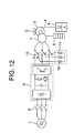
- Fig. 12 is a constructional view of a control apparatus for an elevator including such a kind of known dynamic brake as disclosed in Japanese patent application laid-open No. H09-9699 for instance.
- 1 designates a permanent magnet synchronous motor acting as a winch
- 2 a brake
- 3 a sheave
- 4 a rope wrapped around the sheave 3
- 5 a car connected with one end of the rope 4
- 6 a counter weight connected with the other end of the rope 4 for compensating for half the weight of the car 5 and the movable or carrying load.
- 7 designates a three-phase AC power supply
- 8 a magnetic contactor
- 9 an inverter for supplying electric power of a variable voltage and a variable frequency (VVVF) to the motor 1
- 10 a switching device for brake switching
- 11 an external impedance circuit for dynamic braking comprising a resistor 16.
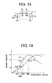
- Fig. 13 is an equivalent circuit showing a dynamic brake circuit in more detail.
- 1 a designates a speed induced voltage (E) of the motor 1, 1b a winding resistance (Rm) of the motor 1, 1c a winding inductance (Lm) of the motor 1, and 16 a resistance (RL) constituting the above-mentioned external impedance 11 for dynamic braking. That is, the dynamic brake circuit is composed of the winding resistance (Rm) and the winding inductance (Lm) of the winding of the motor 1, the external impedance (RL) and the power supply (E) due to the speed induced voltage generated by the rotation of the motor.
- the dynamic brake circuit has the following characteristic: that is, as the rotational speed of the motor increases, the speed induced voltage is rising, in accordance with which the electric current is increasing so that the braking torque becomes greater and greater.
- the frequency of the electric current rises to exceed a certain frequency due to a further increase of the motor rotational speed, however, the influence of inductance increases so the phase difference becomes greater, thus decreasing the braking torque.
- Fig. 14 shows the dynamic brake characteristic of the dynamic brake circuit of Fig. 13.
- the magnetic contactor 8 is closed and the brake switching device 10 is set to side a, so that the electric power fed from the three-phase AC power supply 7 is supplied to the motor 1 through the inverter 9 which converts the voltage and frequency of the electric power. Thereafter, the brake 2 is released so that the sheave 3 is driven to rotate by means of the motor 1 thereby to move the car 5 in a vertical direction.
- the inverter 9 is stopped and the magnetic contactor 8 is opened to isolate the motor 1 from the three-phase AC power supply 7, and at the same time the brake 2 is closed or actuated to brake the rotation of the sheave 3, thereby decelerating the car 5. Further, simultaneous with this, the brake switching device 10 is switched to be connected to side b so that the terminals of the motor 1 are short circuited with each other through the external impedance 11. As a result, a braking force is generated in the rotating motor 1 to assist the deceleration of the car 5.
- This dynamic brake can also be applied to rescue operation after an emergency stop of an elevator. That is, when the elevator is stopped in emergency due to power failure or other reasons, the car 5 general stops at a location displaced from a floor level. Accordingly, in order to rescue passengers in the car, it is required that the brake 2 be released to cause the motor 1 and the sheave 3 to rotate under the action of an unbalanced torque based on a difference in mass between the car 5 and the counter weight 6 thereby to move the car to the nearest floor level and stop it there. At this time, in the case of the winch using the permanent magnet synchronous the motor 1, by short circuiting the motor terminals, the motor generally comes to act as a dynamic brake, thereby making it possible to suppress the speed increase of the car to permit its gradual movement.
- the resistance value R of the shorted circuit is equal to the sum of the winding resistance Rm of the motor (1 b) and the external resistance RL(16), and the reactance X is a value proportional to the winding inductance Lm(1 c) of the motor and the rotational speed thereof.
- the phase of the electric current flowing through the motor is delayed with respect to the induced voltage E(1a) by the influence of the reactance X.
- the torque characteristic (dynamic brake characteristic) of such a circuit system is shown in Fig. 14.
- the braking torque exhibits a characteristic having a maximum value at a certain speed. That is, the braking torque rises in accordance with the increasing rotational speed of the motor, but falls after it has reached a peak at a certain speed.
- the reason for the braking torque increasing in accordance with the increasing rotational speed is that as the rotational speed increases, the voltage E(1a) induced in the motor also is increased, thereby increasing the electric current.
- the reason for the braking torque falling from the certain speed is that as the rotational speed increases, the influence of the reactance X becomes greater and greater, so that the phase of the electric current is further delayed, as a consequence of which the torque no more increases even if the electric current increases.
- the speed at which the a torque is reached is decided by the ratio (R/X) of the resistance value R to the reactance X of the shorted circuit, and hence the maximum torque is governed by the reactance X. Accordingly, there can be obtained various torque characteristics S1, S2 in accordance with the value of an external resistance RL, as shown in Fig. 14. In this case, the external resistance value RL is greater in S2 than in S1, but the maximum torque is governed by the reactance X of the shorted circuit (including a motor internal reactance), so that the maximum torque decreases in accordance with the increasing reactance X.
- the car when this is applied to rescue operation, the car will be moved at a speed which is decided at an intersection with the unbalanced torque (see Fig. 14). Therefore, by varying the external resistance RL, an arbitrary car speed can be obtained. For example, when the external resistance is made large with the unbalanced torque being ⁇ a, the braking torque characteristic is changed from S1 to S2, and the intersection is thus moved from point Pa1 to point Pa2. As a result, the rotational speed of the motor is increased from Na1 to Na2. In addition, when the unbalanced torque becomes larger depending upon a variation in the number of passengers in the car with the same external resistance value, the rotational speed of the motor is increased from Na2 to Nb2 in the case of the characteristic of S2.
- the rotational speed can be reduced to Nb1.
- the car speed or the rotational speed of the motor can be set to an arbitrary value.
- the dynamic braking method in the known control apparatus for an elevator as described above is primarily aimed at using the dynamic brake as an auxiliary means for performing an emergency stop by short circuiting motor terminals with one another directly or through an external resistance, and as a result, there arise problems as stated below.
- the unbalanced torque based on the difference in mass between the car and the counter weight is greatly varied depending upon the number of passengers at the time of rescue operation, and such a torque variation might result in a wide range from a balanced condition to as much as 1.5 times more than the rated torque of the motor.
- the internal reactance becomes large, thus resulting in reduction in the maximum torque of the dynamic brake. Accordingly, in cases where the unbalanced torque is large, e.g., ⁇ c, as shown in Fig. 14, the maximum value of the dynamic brake torque might be exceeded, so acceleration of the car during the rescue operation could not be suppressed.
- the present invention is intended to solve the problems as referred to above, and has for its object to provide a control apparatus for an elevator, and in particular, a dynamic brake system, which is capable of suppressing the acceleration of a car at the time of rescue operation irrespective of the number of passengers in the car so as to enable the car to be moved to the nearest floor at a fixed or constant speed.
- the present invention reside in a control apparatus for an elevator in which a permanent magnet synchronous motor using a permanent magnet as a field magnet is provided as a winch, with respective phase terminals of the permanent magnet synchronous motor being short circuited to form a dynamic brake circuit, characterized by including: capacitors for short circuiting the respective phase terminals of the permanent magnet synchronous motor when the dynamic brake circuit is formed; and a switching device for switching the respective phase terminals of the permanent magnet synchronous motor from a drive circuit to the capacitors to provide connections therebetween.
- the present invention is characterized by further including a circuit for switching the capacitors between a star connection and a delta connection so as to short circuit the respective phase terminals of the permanent magnet synchronous motor, wherein the capacitance of the dynamic brake circuit is made variable.
- the present invention is characterized in that the capacitors for short circuiting the respective phase terminals of the permanent magnet synchronous motor comprise a plurality of capacitors each with a switch connected in parallel, the plurality of capacitors being connected in series, or in parallel, or in series and parallel, with respect to one another, so that the capacitance of the dynamic brake circuit is made variable by opening or closing each of the switches.
- the present invention is characterized in that a reactor is provided for each phase of the permanent magnet synchronous motor at a location between each of the capacitors and each phase of the motor.
- each of the reactors includes a one with a tap changer having a plurality of taps, and the inductance of the dynamic brake circuit is made variable.
- the present invention is characterized by including: a rescue operation execution determining section for determining, based on a command from an elevator control panel, whether rescue operation is to be executed; a brake condition extracting section for extracting a braking condition of the elevator from the elevator control panel; and a short circuit selecting section for changing, upon receipt of a rescue operation executing command from the rescue operation execution determining section, the capacitance or inductance of the dynamic brake circuit by driving either one of a changing circuit for the star connection and the delta connection, switches of the capacitors and tap changers of the reactors based on the braking condition of the elevator extracted by the brake condition extracting section.
- the present invention in the rescue operation under failure of an elevator that is driven by a winch using a permanent magnet motor, it is possible to reduce the combined or synthesized impedance of the inductance and the capacitors at a specific rotational speed of the motor by inserting capacitors in the dynamic brake circuit of the motor in series with the phase windings, respectively. As a result, a difference in phase between an electric current flowing through the dynamic brake circuit and a voltage induced in the motor can be reduced, whereby braking torque can be increased at the specific rotational speed.
- Fig. 1 is a constructional view of a control apparatus for an elevator according to one embodiment of the present invention, in which a winch using a permanent magnet motor is provided and a dynamic brake circuit is employed.
- 1 designates a permanent magnet synchronous motor that acts as a winch
- 2 a brake
- 3 a sheave
- 4 a rope wrapped around the sheave 3
- 5 a car connected with one end of the rope 4
- 6 a counter weight that is connected with the other end of the rope 4 for compensating for half the weight of the car 5 and a movable load.
- 7 designates a three-phase AC power supply
- 8 an electromagnetic contactor
- 9 an inverter that supplies electric power of a variable voltage and a variable frequency (VVVF) to the motor 1
- 10 a switching device for braking switching
- 11 an external impedance circuit for dynamic braking comprising capacitors 13, and 12 reactors.
- the capacitors 13 are provided as the external impedance circuit 11 for dynamic braking. Moreover, in order to suppress the surge voltage of the inverter 9, the reactor 12 may be inserted in each phase between the inverter 9 and the motor 1.
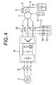
- Fig. 4 is a configuration example when the reactors 12 are not provided, but in which reactors 14 are added in such a manner as to be connected, as an external impedance circuit 11, in series with the capacitors 13, respectively.
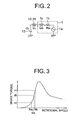
- the dynamic brake characteristic in this case is shown in Fig. 3.
- the shorted circuit is a series circuit of an internal impedance (Rm, Lm) of the motor 1 and the external capacitors CL(13) and the reactors LL (12 or 14).
- the maximum brake torque value can be made a value by far greater than the rated torque of the motor by properly selecting CL and LL.
- the brake torque has a characteristic that it increases suddenly from a certain rotational speed of the motor, if the unbalanced torque changes to values such as ⁇ a, ⁇ b and ⁇ c, the rotational speed is substantially the same such as Na, Nb and Nc. Accordingly, a stable intersection between the dynamic brake torque and the unbalanced torque can be obtained irrespective of the number of passengers, thus making it easy to perform the operation of moving the car to the nearest floor at a constant speed in a safe manner.
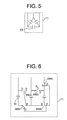
- Fig. 5 shows another example of the external impedance circuit 11.
- Fig. 5 by switching the capacitor connection from a star connection into a delta connection in accordance with the winding inductance Lm of the motor 1, the value of the capacitance C of the capacitor can be changed to ensure a desired brake torque characteristic even without the reactor LL, whereby the cost can be reduced to the extent that the reactor is not needed.
- Fig. 6 One example of a circuit for switching the capacitor connection between the star connection and the delta connections is shown in Fig. 6.
- Fig. 6 five switches SW1 - SW5 are used, and they are switched to side S for the star connection, and to side D for the delta connection.
- Fig. 7 shows that a plurality of capacitors 13 are arranged in series with one another in such a manner that the capacitance C is switched over by means of a plurality of switches SW.
- capacitors 13 with switches SW arranged in a manner as shown in Fig. 8 may be arranged in combination in parallel or series with one another.
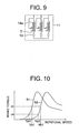
- Fig. 9 shows a plurality of reactors 14a each with intermediate taps are arranged in such a manner that the inductance L can be changed to ensure a desired brake torque characteristic by switching the taps by means of tap changers T in accordance with the winding inductance Lm of the motor 1.
- the brake torque can be changed to values such as S1, S2 in Fig. 10 by switching L or C as stated above, so that the terminal speed of the car during rescue operation can be changed according to the situation.
- the capacitance of the capacitor required to obtain a car speed suitable for rescue operation becomes considerably large with respect to the motor inductance, but in recent years, a compact capacitor of a large capacitance such as an electric double layer capacitor is coming into practical use, and utility thereof for a portable rescue apparatus is expected.
- Fig. 11 is a view showing one example of the configuration of a portion, particularly related to controlling rescue operation, of a control system in the control apparatus for an elevator according to the present invention, in which control parts such as an electromagnetic contactor 8, an inverters 9, and the like are omitted.
- the switches and taps (see Fig. 5 - Fig. 9) of the external impedance are switched to change the terminal velocity of the car during the rescue operation according to the situation.
- 100 designates an elevator control panel that generally controls the operation of the elevator, and 103 a rescue operation execution determining section that determines whether to execute a rescue operation and generates a command. For example, when a motor drive apparatus fails, disabling the normal operation of the elevator, the rescue operation execution determining section receives a command from the elevator control panel 100 to activate the control circuit, so that a short circuiting condition of the brake circuit is selected to form a shorted circuit, thereby releasing the brake to execute rescue operation.
- a command for changing the moving or traveling speed of the car is given to a short circuit selecting section 111 to be described later, so that the construction of a shorted circuit or external impedance circuit 11 is changed, thereby adjusting the moving speed of the car to a prescribed value.
- a brake switching device 10 designates a brake switching device 10 shown in Fig. 1, Fig. 4, etc., that comprises a contactor for isolating the motor 1 in a motor main circuit from a drive circuit including the inverter 9, etc., to switch the connection of the motor to the shorted circuit.
- 107 designates a dynamic brake forming circuit that receives a command from the rescue operation execution determining section 103 to drive the prescribed brake switching device 10, thereby forming a circuit that can carry out dynamic braking.
- 109 designates a brake releasing circuit that releases the brake 2 by a brake release command from the control panel 100.
- the car 5 At the time of rescue operation, by releasing the brake 2 based on the command from the rescue operation execution determining section 103 after the formation of the dynamic brake circuit, the car 5 begins to move while being braked under the action of an unbalanced load between the car and the weight 6, so that it moves to a rescue floor by going up or down substantially at a prescribed speed.
- a brake condition extracting section that the internal resistances or inductances of motors vary one from another during rescue operation, as a result of which the moving speeds of cars employing such motors also vary one from another.
- a short circuit selecting section that selects the condition of a shorted circuit (that is, whether the circuit of a capacitor to be short circuited is a star connection or a delta connection, whether the switch SW of each capacitor is short circuited, whether the intermediate taps of each reactor are short circuited, etc.) based on the data extracted by the brake condition extracting section 105, thereby forming required short circuits. Moreover, the configuration of the shorted circuits are changed according to a command from the rescue operation execution determining section 103.
- 113 designates a switch/tap changing circuit that drives the switches SW and tap changers T in response to a command of the short circuit selecting section 111.
- a control apparatus for an elevator in which a permanent magnet synchronous motor using a permanent magnet as a field magnet is provided as a winch, with respective phase terminals of the permanent magnet synchronous motor being short circuited to form a dynamic brake circuit, characterized by including: capacitors for short circuiting the respective phase terminals of the permanent magnet synchronous motor when the dynamic brake circuit is formed; and a switching device for switching the respective phase terminals of the permanent magnet synchronous motor from a drive circuit to the capacitors to provide connections therebetween.
- the combined impedance of the inductance in the permanent magnet synchronous motor and the capacitors can be reduced at a specific rotational speed of the motor, so that a difference in phase between an electric current flowing through the dynamic brake circuit and a voltage induced can be reduced.
- braking torque can be increased at the specific rotational speed of the motor, whereby rescue operation after an emergency stop of the car can be carried out substantially at a constant speed irrespective of a car load for example.
- a circuit for switching the capacitors between a star connection and a delta connection so as to short circuit the respective phase terminals of the permanent magnet synchronous motor, wherein the capacitance of the dynamic brake circuit is made variable.
- the range of the rotational speed of the motor in which the brake torque is made large can be changed.
- the capacitors for short circuiting the respective phase terminals of the permanent magnet synchronous motor comprise a plurality of capacitors each with a switch connected in parallel, the plurality of capacitors being connected in series, or in parallel, or in series and parallel, with respect to one another, so that the capacitance of the dynamic brake circuit is made variable by opening or closing each of the switches.
- the range of the rotational speed of the motor in which the brake torque is made large can be changed.
- a reactor is provided for each phase of the permanent magnet synchronous motor at a location between each of the capacitors and each phase of the motor.
- the combined impedance of the inductances of the motor and the reactors as well as the capacitors can be reduced at a specific rotational speed, so that a difference in phase between an electric current flowing through the dynamic brake circuit and a voltage induced can be reduced.
- braking torque can be increased at a specific rotational speed of the motor, whereby rescue operation after an emergency stop of the car can be carried out substantially at a constant speed irrespective of a car load for example.
- each of the reactors includes a one with a tap changer having a plurality of taps, and the inductance of the dynamic brake circuit is made variable.
- the range of the rotational speed of the motor in which the brake torque is made large can be changed.
- the present invention includes: a rescue operation execution determining section for determining, based on a command from an elevator control panel, whether rescue operation is to be executed; a brake condition extracting section for extracting a braking condition of the elevator from the elevator control panel; and a short circuit selecting section for changing, upon receipt of a rescue operation executing command from the rescue operation execution determining section, the capacitance or inductance of the dynamic brake circuit by driving either one of a changing circuit for the star connection and the delta connection, switches of the capacitors and tap changers of the reactors based on the braking condition of the elevator extracted by the brake condition extracting section. Accordingly, by properly changing the range of the rotational speed of the motor in which the brake torque is made large, for example, at the time of rescue operation after an emergency stop of the car, the terminal speed of the car can be changed in accordance with the situation.
Landscapes
- Engineering & Computer Science (AREA)
- Automation & Control Theory (AREA)
- Power Engineering (AREA)
- Mechanical Engineering (AREA)
- Elevator Control (AREA)
- Maintenance And Inspection Apparatuses For Elevators (AREA)
- Control Of Ac Motors In General (AREA)
- Control Of Motors That Do Not Use Commutators (AREA)
- Stopping Of Electric Motors (AREA)
Applications Claiming Priority (1)
| Application Number | Priority Date | Filing Date | Title |
|---|---|---|---|
| PCT/JP2002/006999 WO2004007333A1 (ja) | 2002-07-10 | 2002-07-10 | エレベータの制御装置 |
Publications (3)
| Publication Number | Publication Date |
|---|---|
| EP1520829A1 true EP1520829A1 (de) | 2005-04-06 |
| EP1520829A4 EP1520829A4 (de) | 2008-04-30 |
| EP1520829B1 EP1520829B1 (de) | 2020-04-01 |
Family
ID=30022634
Family Applications (1)
| Application Number | Title | Priority Date | Filing Date |
|---|---|---|---|
| EP02745914.8A Expired - Lifetime EP1520829B1 (de) | 2002-07-10 | 2002-07-10 | Steuerung für aufzug |
Country Status (5)
| Country | Link |
|---|---|
| EP (1) | EP1520829B1 (de) |
| JP (1) | JP4330072B2 (de) |
| KR (1) | KR100621475B1 (de) |
| CN (1) | CN1553878B (de) |
| WO (1) | WO2004007333A1 (de) |
Cited By (14)
| Publication number | Priority date | Publication date | Assignee | Title |
|---|---|---|---|---|
| WO2006059182A1 (en) * | 2004-12-02 | 2006-06-08 | Otis Elevator Company | Device and process to rescue passengers trapped in an elevator car and elevator equipped therewith |
| WO2007139477A1 (en) * | 2006-06-01 | 2007-12-06 | Digisign Ab | Circuit device for a braked motor |
| WO2008052693A1 (de) * | 2006-10-31 | 2008-05-08 | Knorr-Bremse Systeme für Schienenfahrzeuge GmbH | Traktionsantrieb eines schienenfahrzeugs zum antreiben und zum generatorischen bremsen |
| EP1921736A3 (de) * | 2006-11-10 | 2008-10-29 | TBK Co., Ltd. | Elektromagnetischer Retarder |
| FR2920611A1 (fr) * | 2007-09-04 | 2009-03-06 | Alstom Transport Sa | Dispositif de freinage electrique securitaire avec moteur a aimants permanents et regulation du couple de freinage. |
| WO2011051571A1 (en) * | 2009-11-02 | 2011-05-05 | Kone Corporation | Braking apparatus, electric drive, and elevator system |
| US8076878B2 (en) | 2006-10-31 | 2011-12-13 | Knorr-Bremse Systeme Fur Schienenfahrzeuge Gmbh | Traction drive of a rail vehicle for driving and generative braking with load correction |
| CN102602768A (zh) * | 2012-03-09 | 2012-07-25 | 上海微频莱机电科技有限公司 | 电梯自救系统 |
| CN103964273A (zh) * | 2014-04-29 | 2014-08-06 | 宁波宏大电梯有限公司 | 基于永磁同步电机的电梯的溜车速度的控制方法 |
| DE102013209527A1 (de) * | 2013-05-23 | 2014-11-27 | Zf Friedrichshafen Ag | Schutzschaltung für einen Aktuator, Aktuatorvorrichtung und Verfahren zum Betreiben eines elektrischen Aktuators |
| EP3072842A1 (de) * | 2015-03-23 | 2016-09-28 | Kone Corporation | Rettungssystem für einen aufzug |
| EP3219655A1 (de) * | 2016-03-14 | 2017-09-20 | Kone Corporation | Verfahren zur bestimmung der geschwindigkeit eines elektromotors, das verfahren verwendende aufzugssteuerungseinheit und computerprogrammprodukt |
| EP3418233A4 (de) * | 2016-02-15 | 2019-11-13 | Hitachi, Ltd. | Aufzug und steuerungsvorrichtung für einen aufzug |
| EP4346084A1 (de) * | 2022-09-29 | 2024-04-03 | Guangzhou Haoyang Electronic Co., Ltd. | Motoranordnung zur verlangsamung der fallgeschwindigkeit einer bühnenleuchte bei stromausfall und bühnenleuchte |
Families Citing this family (29)
| Publication number | Priority date | Publication date | Assignee | Title |
|---|---|---|---|---|
| JP4558352B2 (ja) * | 2004-03-04 | 2010-10-06 | 三菱電機株式会社 | エレベータの故障時救出運転装置 |
| EP1918239B1 (de) * | 2005-08-25 | 2016-09-21 | Mitsubishi Denki Kabushiki Kaisha | Aufzugsvorrichtung |
| JP4827465B2 (ja) * | 2005-09-01 | 2011-11-30 | 株式会社日立製作所 | エレベーター装置 |
| CN101164855B (zh) * | 2006-10-20 | 2010-09-22 | 王秋楠 | 一种电梯异常脱困装置 |
| KR101121793B1 (ko) * | 2007-04-26 | 2012-03-20 | 미쓰비시덴키 가부시키가이샤 | 엘리베이터 장치 |
| JP2012020825A (ja) * | 2010-07-13 | 2012-02-02 | Toshiba Elevator Co Ltd | エレベータのブレーキ制御装置 |
| JP2012184043A (ja) * | 2011-03-03 | 2012-09-27 | Toshiba Elevator Co Ltd | エレベータ装置 |
| JP5616286B2 (ja) * | 2011-05-11 | 2014-10-29 | 株式会社日立製作所 | エレベーター装置 |
| KR101230629B1 (ko) * | 2011-09-30 | 2013-02-06 | 티센크루프엘리베이터코리아 주식회사 | 엘리베이터의 다이내믹 제동 부재 냉각 시스템 |
| CN103095189A (zh) * | 2011-10-28 | 2013-05-08 | 康力电梯股份有限公司 | 一种超高速电梯封星防护处理方法 |
| CN103580499A (zh) * | 2012-08-09 | 2014-02-12 | 成都进界科技有限公司 | 单阻尼单电阻星形连接无振制动变频装置 |
| CN103633893A (zh) * | 2012-08-27 | 2014-03-12 | 成都酷玩网络科技有限公司 | 单阻尼混合星形连接无振制动变频装置 |
| CN103762821B (zh) * | 2014-02-13 | 2017-01-18 | 哈尔滨工业大学 | 电磁制动直线电机系统及其控制方法 |
| JP6301511B2 (ja) * | 2017-01-04 | 2018-03-28 | 株式会社日立産機システム | モータシステム |
| CN107857180A (zh) * | 2017-11-28 | 2018-03-30 | 广东省特种设备检测研究院珠海检测院 | 一种电梯轿厢意外移动保护功能的检测系统及方法 |
| CN108004973B (zh) * | 2017-12-25 | 2023-11-21 | 深圳市威捷机电股份公司 | 控制停电时能手动起落闸杆的道闸电路 |
| EP3560874B1 (de) * | 2018-04-26 | 2021-12-01 | KONE Corporation | Verfahren und vorrcihtung für die zustandsüberwachung einer induktiven bremsvorrichtung einer aufzugskabine |
| JP6770022B2 (ja) * | 2018-06-04 | 2020-10-14 | ファナック株式会社 | サーボアンプ選定装置、サーボアンプ選定方法及びプログラム |
| CN111252637A (zh) * | 2018-12-03 | 2020-06-09 | 株式会社日立制作所 | 电梯控制系统及电梯控制方法 |
| US20210101777A1 (en) * | 2019-10-03 | 2021-04-08 | Otis Elevator Company | Elevator brake control |
| CN110835041B (zh) * | 2019-11-07 | 2021-04-23 | 迅达(中国)电梯有限公司 | 电梯永磁同步曳引机的封星电路设计方法 |
| CN111056392B (zh) * | 2019-12-16 | 2021-10-29 | 迅达(中国)电梯有限公司 | 电梯永磁同步曳引机的测试装置和测试方法 |
| JP7521383B2 (ja) * | 2020-11-11 | 2024-07-24 | 株式会社Ihi | 発電機の過回転防止回路 |
| JP7716856B2 (ja) * | 2021-01-14 | 2025-08-01 | Ntn株式会社 | ブレーキ制御装置 |
| TW202229150A (zh) * | 2021-01-25 | 2022-08-01 | 永大機電工業股份有限公司 | 具自動救出功能的電梯控制模組 |
| FR3125481A1 (fr) * | 2021-07-21 | 2023-01-27 | Mnd France | Chariot pour tyrolienne équipé d’un dispositif de freinage dissipatif |
| CN114835048B (zh) * | 2022-04-07 | 2026-03-13 | 通力电梯有限公司 | 用于电梯的控制装置 |
| CN115072531B (zh) * | 2022-06-23 | 2023-10-27 | 重庆大学 | 一种提升电梯永磁同步曳引机封星转矩方法 |
| CN116374756B (zh) * | 2023-03-31 | 2025-11-21 | 通力电梯有限公司 | 用于电梯的控制装置和控制系统 |
Family Cites Families (9)
| Publication number | Priority date | Publication date | Assignee | Title |
|---|---|---|---|---|
| US3522499A (en) * | 1966-09-28 | 1970-08-04 | Tokyo Shibaura Electric Co | Brushless motor having improved solid state commutation |
| JPS60135097U (ja) * | 1984-02-16 | 1985-09-07 | 株式会社明電舎 | 誘導電動機の制御回路 |
| FI97718C (fi) * | 1995-03-24 | 1997-02-10 | Kone Oy | Hissimoottorin hätäkäyttölaite |
| JP3309648B2 (ja) * | 1995-06-22 | 2002-07-29 | 三菱電機株式会社 | エレベータの制御装置 |
| FI112198B (fi) * | 1997-04-04 | 2003-11-14 | Kone Corp | Menetelmä hissin kestomagnetoitua synkronimoottoria ohjaavan sähkökäytön parametrien määrittämiseksi |
| KR100303011B1 (ko) * | 1998-12-12 | 2002-05-09 | 장병우 | 엘리베이터의운전제어장치 |
| JP2000309475A (ja) * | 2000-01-01 | 2000-11-07 | Mitsubishi Electric Corp | エレベータ装置 |
| JP4663849B2 (ja) * | 2000-06-14 | 2011-04-06 | 三菱電機株式会社 | エレベータの制御装置 |
| JP3521861B2 (ja) * | 2000-10-06 | 2004-04-26 | 三菱電機株式会社 | エレベータの制御装置 |
-
2002
- 2002-07-10 EP EP02745914.8A patent/EP1520829B1/de not_active Expired - Lifetime
- 2002-07-10 WO PCT/JP2002/006999 patent/WO2004007333A1/ja not_active Ceased
- 2002-07-10 KR KR1020047003289A patent/KR100621475B1/ko not_active Expired - Fee Related
- 2002-07-10 CN CN02817545XA patent/CN1553878B/zh not_active Expired - Fee Related
- 2002-07-10 JP JP2004521092A patent/JP4330072B2/ja not_active Expired - Fee Related
Cited By (25)
| Publication number | Priority date | Publication date | Assignee | Title |
|---|---|---|---|---|
| WO2006059182A1 (en) * | 2004-12-02 | 2006-06-08 | Otis Elevator Company | Device and process to rescue passengers trapped in an elevator car and elevator equipped therewith |
| WO2007139477A1 (en) * | 2006-06-01 | 2007-12-06 | Digisign Ab | Circuit device for a braked motor |
| WO2008052693A1 (de) * | 2006-10-31 | 2008-05-08 | Knorr-Bremse Systeme für Schienenfahrzeuge GmbH | Traktionsantrieb eines schienenfahrzeugs zum antreiben und zum generatorischen bremsen |
| US8076878B2 (en) | 2006-10-31 | 2011-12-13 | Knorr-Bremse Systeme Fur Schienenfahrzeuge Gmbh | Traction drive of a rail vehicle for driving and generative braking with load correction |
| US8179063B2 (en) | 2006-10-31 | 2012-05-15 | Knorr-Bremse Systeme Fur Schienenfahrzeuge Gmbh | Traction drive of a rail vehicle for driving and generative braking |
| EP1921736A3 (de) * | 2006-11-10 | 2008-10-29 | TBK Co., Ltd. | Elektromagnetischer Retarder |
| FR2920611A1 (fr) * | 2007-09-04 | 2009-03-06 | Alstom Transport Sa | Dispositif de freinage electrique securitaire avec moteur a aimants permanents et regulation du couple de freinage. |
| EP2033833A3 (de) * | 2007-09-04 | 2015-11-18 | ALSTOM Transport Technologies | Elektrische Sicherheitsbremsvorrichtung mit Dauermagnetmotor und Regulierung des Bremsmoments |
| US8148925B2 (en) | 2007-09-04 | 2012-04-03 | Alstom Transport Sa | Electric safety braking device with permanent magnet motor and breaking torque control |
| CN102712442B (zh) * | 2009-11-02 | 2014-09-10 | 通力股份公司 | 制动装置、电驱动器、和电梯系统 |
| WO2011051571A1 (en) * | 2009-11-02 | 2011-05-05 | Kone Corporation | Braking apparatus, electric drive, and elevator system |
| CN102712442A (zh) * | 2009-11-02 | 2012-10-03 | 通力股份公司 | 制动装置、电驱动器、和电梯系统 |
| US8890448B2 (en) | 2009-11-02 | 2014-11-18 | Kone Corporation | Braking apparatus, electric drive, and elevator system |
| CN102602768A (zh) * | 2012-03-09 | 2012-07-25 | 上海微频莱机电科技有限公司 | 电梯自救系统 |
| DE102013209527A1 (de) * | 2013-05-23 | 2014-11-27 | Zf Friedrichshafen Ag | Schutzschaltung für einen Aktuator, Aktuatorvorrichtung und Verfahren zum Betreiben eines elektrischen Aktuators |
| WO2014187634A3 (de) * | 2013-05-23 | 2015-05-07 | Zf Friedrichshafen Ag | Schutzschaltung für einen aktuator, aktuatorvorrichtung und verfahren zum betreiben eines elektrischen aktuators |
| CN103964273A (zh) * | 2014-04-29 | 2014-08-06 | 宁波宏大电梯有限公司 | 基于永磁同步电机的电梯的溜车速度的控制方法 |
| CN103964273B (zh) * | 2014-04-29 | 2016-05-11 | 宁波宏大电梯有限公司 | 基于永磁同步电机的电梯的溜车速度的控制方法 |
| EP3072842A1 (de) * | 2015-03-23 | 2016-09-28 | Kone Corporation | Rettungssystem für einen aufzug |
| US10273116B2 (en) | 2015-03-23 | 2019-04-30 | Kone Corporation | Jerk limiting in elevator rescue system |
| EP3418233A4 (de) * | 2016-02-15 | 2019-11-13 | Hitachi, Ltd. | Aufzug und steuerungsvorrichtung für einen aufzug |
| EP3219655A1 (de) * | 2016-03-14 | 2017-09-20 | Kone Corporation | Verfahren zur bestimmung der geschwindigkeit eines elektromotors, das verfahren verwendende aufzugssteuerungseinheit und computerprogrammprodukt |
| CN107188006A (zh) * | 2016-03-14 | 2017-09-22 | 通力股份公司 | 确定电动机速度的方法,电梯控制单元和计算机程序产品 |
| EP4346084A1 (de) * | 2022-09-29 | 2024-04-03 | Guangzhou Haoyang Electronic Co., Ltd. | Motoranordnung zur verlangsamung der fallgeschwindigkeit einer bühnenleuchte bei stromausfall und bühnenleuchte |
| US12308778B2 (en) | 2022-09-29 | 2025-05-20 | Guangzhou Haoyang Electronic Co., Ltd. | Motor assembly for slowing down falling speed of stage light fixture on power failure, and stage light fixture |
Also Published As
| Publication number | Publication date |
|---|---|
| CN1553878A (zh) | 2004-12-08 |
| KR20040035754A (ko) | 2004-04-29 |
| JP4330072B2 (ja) | 2009-09-09 |
| WO2004007333A1 (ja) | 2004-01-22 |
| JPWO2004007333A1 (ja) | 2005-11-10 |
| EP1520829A4 (de) | 2008-04-30 |
| KR100621475B1 (ko) | 2006-09-13 |
| CN1553878B (zh) | 2011-08-10 |
| EP1520829B1 (de) | 2020-04-01 |
Similar Documents
| Publication | Publication Date | Title |
|---|---|---|
| EP1520829B1 (de) | Steuerung für aufzug | |
| EP2496507B1 (de) | Bremsvorrichtung und elektrischer antrieb für ein aufzugsystem und aufzugsystem, das sie aufweist | |
| JP5549682B2 (ja) | エレベータの救出運転装置 | |
| JP4986541B2 (ja) | エレベータ制御装置 | |
| JP2000211838A (ja) | 停電時のエレベ―タ救出運転制御方法 | |
| CN101177230B (zh) | 电梯用制动控制装置 | |
| CN101389560A (zh) | 电梯控制装置 | |
| US4441584A (en) | AC Elevator control system | |
| JP2010280458A (ja) | エレベータの制御装置 | |
| JP4689337B2 (ja) | エレベータ装置 | |
| US6971482B2 (en) | Elevator control device | |
| JP2008230797A (ja) | エレベータ用制御装置 | |
| US4661757A (en) | Controller for AC elevator | |
| JP4391613B2 (ja) | 巻上機制御装置 | |
| JPH04286587A (ja) | リニアモータ式エレベータ制御装置 | |
| JPS5844592B2 (ja) | エレベ−タセイギヨホウシキ | |
| RU2298520C2 (ru) | Электропривод механизма подъема и опускания груза грузоподъемного крана | |
| JP2006176257A (ja) | エレベータ制御装置 | |
| KR870001020Y1 (ko) | 교류엘리베이터 제어장치 | |
| EP3429950B1 (de) | Verwaltung einer mehrfachspulenbremse für ein aufzugssystem | |
| JPS6125631B2 (de) | ||
| JP2024166701A (ja) | 巻上機の制御装置およびその制御方法 | |
| JPS5911503B2 (ja) | 交流エレベ−タの制御装置 | |
| JP2022128144A (ja) | 巻胴式エレベータの制御装置 | |
| JP2009029589A (ja) | 巻上機の運転制御装置、及び運転制御方法 |
Legal Events
| Date | Code | Title | Description |
|---|---|---|---|
| PUAI | Public reference made under article 153(3) epc to a published international application that has entered the european phase |
Free format text: ORIGINAL CODE: 0009012 |
|
| 17P | Request for examination filed |
Effective date: 20040220 |
|
| AK | Designated contracting states |
Kind code of ref document: A1 Designated state(s): AT BE BG CH CY CZ DE DK EE ES FI FR GB GR IE IT LI LU MC NL PT SE SK TR |
|
| RBV | Designated contracting states (corrected) |
Designated state(s): DE NL |
|
| RAP1 | Party data changed (applicant data changed or rights of an application transferred) |
Owner name: MITSUBISHI DENKI KABUSHIKI KAISHA |
|
| A4 | Supplementary search report drawn up and despatched |
Effective date: 20080402 |
|
| 17Q | First examination report despatched |
Effective date: 20120611 |
|
| RIC1 | Information provided on ipc code assigned before grant |
Ipc: B66B 1/28 20060101ALI20191022BHEP Ipc: B66B 5/02 20060101AFI20191022BHEP |
|
| GRAP | Despatch of communication of intention to grant a patent |
Free format text: ORIGINAL CODE: EPIDOSNIGR1 |
|
| INTG | Intention to grant announced |
Effective date: 20191211 |
|
| GRAS | Grant fee paid |
Free format text: ORIGINAL CODE: EPIDOSNIGR3 |
|
| GRAA | (expected) grant |
Free format text: ORIGINAL CODE: 0009210 |
|
| STAA | Information on the status of an ep patent application or granted ep patent |
Free format text: STATUS: THE PATENT HAS BEEN GRANTED |
|
| AK | Designated contracting states |
Kind code of ref document: B1 Designated state(s): DE NL |
|
| REG | Reference to a national code |
Ref country code: DE Ref legal event code: R096 Ref document number: 60250114 Country of ref document: DE |
|
| REG | Reference to a national code |
Ref country code: NL Ref legal event code: FP |
|
| REG | Reference to a national code |
Ref country code: DE Ref legal event code: R097 Ref document number: 60250114 Country of ref document: DE |
|
| PLBE | No opposition filed within time limit |
Free format text: ORIGINAL CODE: 0009261 |
|
| STAA | Information on the status of an ep patent application or granted ep patent |
Free format text: STATUS: NO OPPOSITION FILED WITHIN TIME LIMIT |
|
| 26N | No opposition filed |
Effective date: 20210112 |
|
| PGFP | Annual fee paid to national office [announced via postgrant information from national office to epo] |
Ref country code: NL Payment date: 20210615 Year of fee payment: 20 |
|
| PGFP | Annual fee paid to national office [announced via postgrant information from national office to epo] |
Ref country code: DE Payment date: 20210616 Year of fee payment: 20 |
|
| REG | Reference to a national code |
Ref country code: DE Ref legal event code: R071 Ref document number: 60250114 Country of ref document: DE |
|
| REG | Reference to a national code |
Ref country code: NL Ref legal event code: MK Effective date: 20220709 |