EP4346084A1 - Motoranordnung zur verlangsamung der fallgeschwindigkeit einer bühnenleuchte bei stromausfall und bühnenleuchte - Google Patents
Motoranordnung zur verlangsamung der fallgeschwindigkeit einer bühnenleuchte bei stromausfall und bühnenleuchte Download PDFInfo
- Publication number
- EP4346084A1 EP4346084A1 EP22217369.2A EP22217369A EP4346084A1 EP 4346084 A1 EP4346084 A1 EP 4346084A1 EP 22217369 A EP22217369 A EP 22217369A EP 4346084 A1 EP4346084 A1 EP 4346084A1
- Authority
- EP
- European Patent Office
- Prior art keywords
- terminal
- motor
- terminals
- switch
- switch units
- Prior art date
- Legal status (The legal status is an assumption and is not a legal conclusion. Google has not performed a legal analysis and makes no representation as to the accuracy of the status listed.)
- Pending
Links
Images


Classifications
-
- H—ELECTRICITY
- H02—GENERATION; CONVERSION OR DISTRIBUTION OF ELECTRIC POWER
- H02P—CONTROL OR REGULATION OF ELECTRIC MOTORS, ELECTRIC GENERATORS OR DYNAMO-ELECTRIC CONVERTERS; CONTROLLING TRANSFORMERS, REACTORS OR CHOKE COILS
- H02P3/00—Arrangements for stopping or slowing electric motors, generators, or dynamo-electric converters
- H02P3/02—Details of stopping control
-
- F—MECHANICAL ENGINEERING; LIGHTING; HEATING; WEAPONS; BLASTING
- F21—LIGHTING
- F21V—FUNCTIONAL FEATURES OR DETAILS OF LIGHTING DEVICES OR SYSTEMS THEREOF; STRUCTURAL COMBINATIONS OF LIGHTING DEVICES WITH OTHER ARTICLES, NOT OTHERWISE PROVIDED FOR
- F21V14/00—Controlling the distribution of the light emitted by adjustment of elements
-
- F—MECHANICAL ENGINEERING; LIGHTING; HEATING; WEAPONS; BLASTING
- F21—LIGHTING
- F21V—FUNCTIONAL FEATURES OR DETAILS OF LIGHTING DEVICES OR SYSTEMS THEREOF; STRUCTURAL COMBINATIONS OF LIGHTING DEVICES WITH OTHER ARTICLES, NOT OTHERWISE PROVIDED FOR
- F21V21/00—Supporting, suspending, or attaching arrangements for lighting devices; Hand grips
- F21V21/14—Adjustable mountings
- F21V21/15—Adjustable mountings specially adapted for power operation, e.g. by remote control
-
- F—MECHANICAL ENGINEERING; LIGHTING; HEATING; WEAPONS; BLASTING
- F21—LIGHTING
- F21V—FUNCTIONAL FEATURES OR DETAILS OF LIGHTING DEVICES OR SYSTEMS THEREOF; STRUCTURAL COMBINATIONS OF LIGHTING DEVICES WITH OTHER ARTICLES, NOT OTHERWISE PROVIDED FOR
- F21V25/00—Safety devices structurally associated with lighting devices
-
- H—ELECTRICITY
- H02—GENERATION; CONVERSION OR DISTRIBUTION OF ELECTRIC POWER
- H02P—CONTROL OR REGULATION OF ELECTRIC MOTORS, ELECTRIC GENERATORS OR DYNAMO-ELECTRIC CONVERTERS; CONTROLLING TRANSFORMERS, REACTORS OR CHOKE COILS
- H02P3/00—Arrangements for stopping or slowing electric motors, generators, or dynamo-electric converters
- H02P3/06—Arrangements for stopping or slowing electric motors, generators, or dynamo-electric converters for stopping or slowing an individual dynamo-electric motor or dynamo-electric converter
- H02P3/18—Arrangements for stopping or slowing electric motors, generators, or dynamo-electric converters for stopping or slowing an individual dynamo-electric motor or dynamo-electric converter for stopping or slowing an AC motor
- H02P3/24—Arrangements for stopping or slowing electric motors, generators, or dynamo-electric converters for stopping or slowing an individual dynamo-electric motor or dynamo-electric converter for stopping or slowing an AC motor by applying DC to the motor
-
- F—MECHANICAL ENGINEERING; LIGHTING; HEATING; WEAPONS; BLASTING
- F21—LIGHTING
- F21W—INDEXING SCHEME ASSOCIATED WITH SUBCLASSES F21K, F21L, F21S and F21V, RELATING TO USES OR APPLICATIONS OF LIGHTING DEVICES OR SYSTEMS
- F21W2131/00—Use or application of lighting devices or systems not provided for in codes F21W2102/00-F21W2121/00
- F21W2131/40—Lighting for industrial, commercial, recreational or military use
- F21W2131/406—Lighting for industrial, commercial, recreational or military use for theatres, stages or film studios
Definitions
- the present disclosure relates to power electronics, and in particular, relates to a motor assembly for slowing down falling speed of a stage light fixture on power failure, and a stage light fixture.
- a light head of a stage light fixture is usually provided with components such as a focus lens, a magnify lens and the like that are movable along an optical path, components such as a frosting lens, a prism and the like that are swingable with respect to the optical path, and components such as a rotary pattern wheel, a fixed pattern wheel, a color wheel, a shader and the like that are rotatable with respect to the optical path.
- the light head and the support arm of the stage light fixture are also rotatable.
- a motor driver outputs a braking current, and a stepper motor thus generates a braking torque to maintain the components stationary.
- collision buffering is generally implemented by using a brake motor to avoid damages.
- a rotary shaft of a motor unit is braked by a brake pad of a brake unit.
- this braking method increases the thickness of the motor along the direction of the rotary shaft and is more expensive than a common motor. Further, the brake pad will be worn after long-term operation, thereby reducing braking force and affecting the buffering effects.
- two pairs of windings of a two-phase stepper motor are respectively short-circuited via a relay when on power failure, and the motor is driven to rotate by falling of the components, so that the motor generates an induced current formed by an induced electromotive force to generate a braking force, the component thus may not fall quickly.
- This way achieves braking using short circuit of the motor, but the braking torque generated is small. When the component is heavy, the braking torque generated will be less than the gravity of the component, in such situation the component may still fall quickly.
- the present disclosure thus provides a motor assembly for slowing down falling speed of a stage light fixture on power failure, and a stage light fixture, which can effectively reduce the fall speed of the stage light fixture in case of power failure.
- a motor assembly for slowing down falling speed of a stage light fixture on power failure is provided according to the present disclosure.
- the motor assembly includes a motor driver, an automatic transfer switch, a capacitive load, and an alternating current motor.
- the automatic transfer switch is energized, windings of the alternating current motor are kept connected to the motor driver, and in the case that the automatic transfer switch is deenergized, the windings of the alternating current motor are switched to be connected to the capacitive load.
- stage light fixture includes the motor assembly for slowing down falling speed of the stage light fixture in case of the power failure mentioned above.
- the energization and deenergization are controlled by an automatic transfer switch in the motor assembly, such that the motor driver is connected to the windings of the motor in response to be energized and is connected to the capacitive load in response to deenergized.
- the capacitive load makes the phase of the induced current 90° ahead of the phase of the induced voltage, so that the directions of the electromotive forces generated by the armature magnetic field of the motor and the primary magnetic field of the permanent magnet are consistent, and a longitudinal magnetization armature reaction thus may be generated.
- the magnetic flux increases, the induced voltage rises, the induced current rises, and the braking torque thus increases, such that braking of the motor in case of the power failure is achieved, thus slowing down the falling speed of the stage light fixture in case of the power failure.
- the components such as a focus lens, a magnify lens and the like are movable along the optical path
- the components such as a frosting lens, a prism and the like are swingable with respect to the optical path
- the components such as a rotary pattern wheel, a fixed pattern wheel, a color wheel, a shader and the like are rotatable with respect to the optical path.
- a light head and a support arm of the stage light fixture are also rotatable.
- the motor assembly which reduces the falling speed of the stage light fixture in case of a power failure, generates an electromagnetic torque of a braking effect to control the falling speed of the stage light fixture.
- the motor assembly includes a motor driver, an automatic transfer switch, a capacitive load, and an alternating current motor.
- the windings of the alternating current motor are kept connected to the motor driver; and in the case that the automatic transfer switch is deenergized, the windings of the alternating current motor are switched to be connected to the capacitive load, and the capacitive load is a non-polar capacitor.
- the winding of the alternating current motor is connected to the motor drive, and the alternating current motor operates normally; and in the case that the automatic transfer switch is deenergized, the winding of the alternating current motor is connected to the capacitive loads.
- the capacitive load When deenergized, the capacitive load makes the phase of the induced current 90° ahead of the phase of the induced voltage, so that the directions of the electromotive forces generated by the armature magnetic field of the motor and the primary magnetic field of the permanent magnet are consistent, and a longitudinal magnetization armature reaction thus may be generated.
- the magnetic flux increases, the induced voltage rises, the induced current rises, and the braking torque thus increases, thereby reducing the falling speed of the stage light fixture in case of the power failure.
- the capacitive load is a non-polar capacitor, and within an electric cycle of the alternating current motor, forward and reverse charging may be achieved, which can always accommodate electric charge generated by the alternating current motor.
- a plurality of alternating current motors may share one capacitive load, or a plurality of windings of an alternating current motor may be connected in series to connect a capacitive load.
- the automatic transfer switch includes, but is not limited to, a semiconductor switch circuit, and a relay including a direct current relay and an alternating current relay.
- Alternating current motors include, but are not limited to, stepper motors and servo motors.
- a maximum amount of electric charge that may be stored in the capacitive load is greater than or equal to a maximum amount of electric charge generated by the alternating current motor within one electric cycle, and the capacitive load may not be fully charged within one electric cycle of the alternating current motor. In this way, the capacitive load may continue to be charged and discharged, and may never be fully charged, which constantly increasing the torque of the alternating current motor, and continuously reducing the falling speed of the stage light fixture in case of the power failure.
- a capacitance of the capacitive load is greater than or equal to 40 ⁇ F (microfarad).
- the capacitance of the capacitive load may be preferably 70 ⁇ F, such that it is ensured that the AC motor is smoothly braked without jamming or incoherent motion in case of the power failure.
- the automatic transfer switch when the automatic transfer switch includes a normally opened terminal, a normally closed terminal, and a common terminal, on or off of the automatic transfer switch is controlled by a control signal or is at the normally closed terminal or the normally opened terminal due to energization or deenergization, and the winding is a set of turns constituting an electrical line corresponding to a voltage of a transformer.
- the common terminal of the automatic transfer switch is connected to the winding of the alternating current motor
- the normally closed terminal of the automatic transfer switch is connected to two terminals of the capacitive load
- the normally opened terminal of the automatic transfer switch is connected to an output terminal of the motor driver.
- the automatic transfer switch at least includes a normally closed terminal and a common terminal
- on or off of the automatic transfer switch is controlled by a control signal or is closed or opened due to energization or deenergization
- the winding is a group of turns constituting an electrical line corresponding to the voltage value of the transformer
- the common terminal of the automatic transfer switch is connected to the winding of the alternating current motor and the output terminal of the motor driver
- the winding of the alternating current motor is directly connected to the output terminal of the motor driver
- the normally closed terminal of the automatic transfer switch is connected to two terminals of the capacitive load.
- the motor assembly includes a motor driver, an automatic transfer switch, a capacitive load, and an alternating current motor.
- the automatic transfer switch In the case that the automatic transfer switch is energized, windings of the alternating current motor are kept connected to the motor driver, and in the case that the automatic transfer switch is deenergized, the windings of the alternating current motor are switched to be connected to the capacitive load.
- the motor assembly can reduce the fall speed of the stage light fixture in case of the power failure.
- the automatic transfer switch in these embodiments includes one or more switch units.
- Each switch unit includes a common terminal, a normally closed terminal, and a normally opened terminal.
- the common terminal is connected to the windings of the alternating current motor, the normally closed terminal is connected to the capacitive load, and the normally opened terminal is connected to the motor driver.
- the motor assembly is a two-phase motor assembly.
- the two-phase motor assembly includes a motor driver, two automatic transfer switches, two capacitive loads, and a two-phase motor.
- each of the two automatic transfer switch includes two switch units. Therefore, this embodiment includes four switch units. Common terminals of the four switch units are respectively connected to totally four terminals of two windings of the two-phase motor, normally closed terminals of the two switch units connected to the same winding are respectively connected to two terminals of one of the two capacitive loads, and normally opened terminals of the two switch units connected to the same winding are connected to an output terminal of the motor driver.
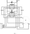
- the two-phase stepper motor assembly in this embodiment includes a motor driver, referred as Driver, two switch units in an automatic transfer switch K1, two switch units in an automatic transfer switch K2, two capacitive loads (a capacitive load C1 and a capacitive load C2), and a two-phase stepper motor M.
- a common terminal 3 of one of the two switch units in the automatic transfer switch K1 is connected to a terminal A+ of the windings of the two-phase motor M
- a common terminal 6 of one of the switch units in the automatic transfer switch K1 is connected to a terminal B+ of the windings of the two-phase motor M.
- a common terminal 3 of one of the two switch units in the automatic transfer switch K2 is connected to a terminal A- of the windings of the two-phase motor M, and a common terminal 6 of the other of the two switch units in the automatic transfer switch K2 is connected to a terminal B- of the windings of the two-phase motor M. It should be noted that it is feasible that each winding corresponds to the two switch units in one automatic transfer switch, instead of crossing each other.
- a normally closed terminal 2 of one of the two switch units in the automatic transfer switch K1 and a normally closed terminal 2 of one of the two switch units in the automatic transfer switch K2 are connected to two terminals of the capacitive load C1.
- a normally closed terminal 7 of one of the two switch units in the automatic transfer switch K1 and a normally closed terminal 7 of one of the two switch units in the automatic transfer switch K2 are connected to two terminals of the capacitive load C2.
- a normally opened terminal 4 of one of the two switch units in the automatic transfer switch K1 is connected to a terminal A+ of the motor driver, referred as Driver, and a normally opened terminal 5 of the other of the two switch units in the automatic transfer switch K1 is connected to a terminal B+ of the motor driver, referred as Driver.
- a normally opened terminal 4 of one of the two switch units in the automatic transfer switch K2 is connected to a terminal A- of the motor driver, referred as Driver
- a normally opened terminal 5 of the other of the two switch units in the automatic transfer switch K2 is connected to a terminal B- of the motor driver, referred as Driver.
- the power supply is supplying power or the switch unit outputs a coil pull-in signal
- the coils of the two switch units in the automatic transfer switch K1 are pulled-in
- the coils of the two switch units in the automatic transfer switch K2 are pulled-in, and the four switch units are normally opened.
- the output terminals of the motor driver referred as Driver
- Driver are connected to the winding of the two-phase motor M via the normally opened terminals of the four switch units; and the two-phase motor M operates according to the output signals of the motor driver, referred as Driver.
- the coils of the two switch units in the automatic transfer switch K1 will be powered down, and the coils of the two switch units in the automatic transfer switch K2 will be also powered down.
- the four switch units are at normally closed terminates.
- the windings of the two-phase motor M are connected to two terminals of the capacitive load C1 and two terminals of the capacitive load C2.
- the components fall under gravity to drive the two-phase motor M to rotate.
- the induced electromotive force generated by the rotation of the two-phase motor M is an alternating current.
- the capacitive load has an alternating current isolation effect, the windings of the two-phase motor M are thus capable of generating an induced current, such that the two-phase motor M generates an electromagnetic torque with a braking effect.
- the component drives the stepper motor to rotate.
- the stepper motor is in a generator state
- the induced electromotive force generated is an alternating current
- the capacitive load has a direct current isolation and direct current interaction effect
- the motor winding can also generate an induced current
- the motor has a braking torque. Since the capacity of the capacitive load is large enough, the current may not be interrupted.
- the capacitive load As a load of the generator, is a capacitive load, and the capacitive load makes the phase of the induced current 90° ahead of the phase of the induced voltage.
- the directions of the electromotive forces generated by the armature magnetic field of the motor and the primary magnetic field of the permanent magnet are the same, and a longitudinal magnetization armature reaction may be generated. In this case, the magnetic flux increases, the induced voltage rises, and the induced current rises.
- the winding is directly short-circuited, it is equivalent to a resistive load with a small resistance value, and the resistive load has no magnetization or demagnetization effect.
- the number N of winding turns and the closed conductor path 1 are inherent properties of the motor, and the values thereof are constant. Since the motor is in a longitudinal axis magnetization armature reaction, the primary magnetic flux ⁇ B increases, the induced current i increases, the electromagnetic force increases, the electromagnetic torque increases, and the motor braking torque increases. In this way, the motor generates a greater braking torque than that in the case of short circuit of the windings at the same rotation speed, and the motor rotation speed is capable of generating a braking torque equal to the gravity at a lower time, such that the component falls at a lower speed, or a heavier component may also be braked.
- the motor assembly is a three-phase motor assembly in this embodiment.
- the three-phase motor assembly includes a motor driver, three automatic transfer switches, three capacitive loads, and a three-phase motor.
- each of the three automatic transfer switches includes a switch unit. Therefore, this embodiment includes three switch units. Output terminals of the motor driver are connected to normally opened terminals of the three switch units, common terminals of the three switch units are connected to three windings of the three-phase motor, totally six terminals of the three capacitive loads are connected in sequence in a ring pattern, and each pair of normally closed terminals of the three switch units is connected to two terminals of each of the capacitive loads.
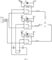
- the three-phase stepper motor assembly in this embodiment includes a motor driver, referred as Driver, a switch unit in an automatic transfer switch K1, a switch unit in an automatic transfer switch K2, a switch unit in an automatic transfer switch K3, three capacitive loads (a capacitive load C 1, a capacitive load C2, and a capacitive load C3), and a three-phase stepper motor M.
- Driver a motor driver
- switch unit in an automatic transfer switch K1 a switch unit in an automatic transfer switch K2
- a switch unit in an automatic transfer switch K3 three capacitive loads (a capacitive load C 1, a capacitive load C2, and a capacitive load C3)
- a three-phase stepper motor M referred as Driver
- a normally opened terminal 5 of the switch unit in the automatic transfer switch K1 is connected to a terminal A-IN of the motor driver, referred as Driver
- a normally opened terminal 5 of the switch unit in the automatic transfer switch K2 is connected to a terminal B-IN of the motor driver, referred as Driver
- a normally opened terminal 5 of the switch unit in the automatic transfer switch K3 is connected to a terminal C-IN of the motor driver, referred as Driver.
- a common terminal 3 (A OUT) of the switch unit in the automatic transfer switch K1 is connected to a terminal A of the windings of the three-phase motor M
- a common terminal 3 (B OUT) of the switch unit in the automatic transfer switch K2 is connected to a terminal B of the winding of the three-phase motor M
- a common terminal 3 (C OUT) of the switch unit in the automatic transfer switch K3 is connected to a terminal C of the winding of the three-phase motor M.
- a normally closed terminal 4 of the switch unit in the automatic transfer switch K1 and a normally closed terminal 4 of the switch unit in the automatic transfer switch K2 are connected to two terminals of the capacitive load C1
- the normally closed terminal 4 of the switch unit in the automatic transfer switch K2 and a normally closed terminal 4 of the switch unit in the automatic transfer switch K3 are connected to two terminals of the capacitive load C2
- the normally closed terminal 4 of the switch unit in the automatic transfer switch K1 and the normally closed terminal 4 of the switch unit in the automatic transfer switch K3 are connected to two terminals of the capacitive load C3.
- the normally closed terminal 4 of the switch unit in the automatic transfer switch K1 and the normally closed terminal 4 of the switch unit in the automatic transfer switch K2 are pairwise connected to two terminals of the capacitive load C1
- the normally closed terminal 4 of the switch unit in the automatic transfer switch K2 and the normally closed terminal 4 of the switch unit in the automatic transfer switch K3 are pairwise connected to two terminals of the capacitive load C2
- the normally closed terminal 4 of the switch unit in the automatic transfer switch K1 and the normally closed terminal 4 of the switch unit in the automatic transfer switch K3 are pairwise connected to two terminals of the capacitive load C3.
- two terminals of the capacitive load C1, two terminals of the capacitive load C2, and two terminals of the capacitive load C3 are connected in sequence in a ring pattern, and the normally closed terminal of the switch unit in the automatic transfer switch K1, the normally closed terminal of the switch unit in the automatic transfer switch K2, and the normally closed terminal of the switch unit in the automatic transfer switch K3 are respectively pairwise connected to two terminals one of the capacitive loads.
- circuit operation of the three-phase stepper motor assembly in this embodiment is the same as the circuit operation of the two-phase stepper motor assembly, which is thus not described herein any further.
- the motor assembly is a three-phase motor assembly in this embodiment.
- the three-phase motor assembly includes a motor driver, three automatic transfer switches, three capacitive loads, and a three-phase motor.
- each of the three automatic transfer switches includes a switch unit. Therefore, this embodiment includes three switch units. Output terminals of the motor driver are connected to normally opened terminals of the three switch units, common terminals of the three switch units are connected to three windings of the three-phase motor, three terminals of the three capacitive loads are connected to each other in a radial pattern, and each of normally closed terminals of the three switch units is connected to the other terminal of one of the capacitive loads.
- the three-phase stepper motor assembly in this embodiment includes a motor driver, referred as Driver, a switch unit in an automatic transfer switch K1, a switch unit in an automatic transfer switch K2, a switch unit in an automatic transfer switch K3, three capacitive loads (a capacitive load C1, a capacitive load C2, and a capacitive load C3), and a three-phase stepper motor M.
- Driver a motor driver
- switch unit in an automatic transfer switch K1 a switch unit in an automatic transfer switch K2
- a switch unit in an automatic transfer switch K3 three capacitive loads (a capacitive load C1, a capacitive load C2, and a capacitive load C3)
- a three-phase stepper motor M referred as Driver
- a normally opened terminal 5 of the switch unit in the automatic transfer switch K1 is connected to a terminal A-IN of the motor driver, referred as Driver
- a normally opened terminal 5 of the switch unit in the automatic transfer switch K2 is connected to a terminal B-IN of the motor driver, referred as Driver
- a normally opened terminal 5 of the switch unit in the automatic transfer switch K3 is connected to a terminal C-IN of the motor driver, referred as Driver.
- a common terminal 3 (A OUT) of the switch unit in the automatic transfer switch K1 is connected to a terminal A of the windings of the three-phase motor M
- a common terminal 3 (B OUT) of the switch unit in the automatic transfer switch K2 is connected to a terminal B of the winding of the three-phase motor M
- a common terminal 3 (C OUT) of the switch unit in the automatic transfer switch K3 is connected to a terminal C of the winding of the three-phase motor M.
- a normally closed terminal 4 of the switch unit in the automatic transfer switch K1 is connected to one terminal of the capacitive load C1, and the other terminal of the capacitive load C1 is connected to one terminal of the capacitive load C2 and one terminal of the capacitive load C3.
- a normally closed terminal 4 of the switch unit in the automatic transfer switch K2 is connected to one terminal of the capacitive load C2, and the other terminal of the capacitive load C2 is connected to one terminal of the capacitive load C1 and one terminal of the capacitive load C3.
- a normally closed terminal 4 of the switch unit in the automatic transfer switch K3 is connected to one terminal of the capacitive load C3, and the other terminal of the capacitive load C3 is connected to one terminal of the capacitive load C1 and one terminal of the capacitive load C2.
- the normally closed terminal 4 of the switch unit in the automatic transfer switch K1 and the normally closed terminal 4 of the switch unit in the automatic transfer switch K2 are pairwise connected to one terminal of the capacitive load C1 and one terminal of the capacitive load C2, and the other terminal of the capacitive load C1 and the other terminal of the capacitive load C2 are connected to each other.
- the normally closed terminal 4 of the switch unit in the automatic transfer switch K1 and the normally closed terminal 4 of the switch unit in the automatic transfer switch K3 are pairwise connected to one terminal of the capacitive load C1 and one terminal of the capacitive load C3, and the other terminal of the capacitive load C1 and the other terminal of the capacitive load C3 are connected to each other.
- the normally closed terminal 4 of the switch unit in the automatic transfer switch K2 and the normally closed terminal 4 of the switch unit in the automatic transfer switch K3 are pairwise connected to one terminal of the capacitive load C2 and one terminal of the capacitive load C3, and the other terminal of the capacitive load C2 and the other terminal of the capacitive load C3 are connected to each other.
- one terminal of the capacitive load C1, one terminal of the capacitive load C2, and one terminal of the capacitive load C3 are connected to each other in a radial pattern, and each of the normally closed terminal of the switch unit in the automatic transfer switch K1, the normally closed terminal of the switch unit in the automatic transfer switch K2, and the normally closed terminal of the switch unit in the automatic transfer switch K3 is connected to one terminal of one of the capacitive loads.
- circuit operation of the three-phase stepper motor assembly in this embodiment is the same as the circuit operation of the two-phase stepper motor assembly, which is thus not described herein any further.
- one terminal of at least one of the windings of the alternating current motor is connected to one corresponding terminal of the motor driver and one corresponding terminal of the capacitive load, and the other terminal of the at least one of the windings of the alternating current motor is connected to the common terminal of the corresponding switch unit, the normally closed terminal of the corresponding switch unit is connected to the other terminal of the capacitor load corresponding to the winding, and the normally opened terminal of the corresponding switch unit is connected to another motor driver corresponding to the winding.
- the motor assembly is a two-phase motor assembly in this embodiment.
- the two-phase motor assembly includes a motor driver, one automatic transfer switch, two capacitive loads, and a two-phase motor.
- the automatic transfer switch includes two switch units. Therefore, this embodiment includes two switch units.
- the motor drive has two terminals for each phase of the motor.
- One of the two terminals of the motor driver for each phase is connected to one terminal of one of the windings and one terminal of one of the two capacitive loads, the other one of the two terminals of the motor driver for each phase is connected to a normally opened terminal of one of the two switch units, a common terminal of the corresponding switch unit is connected to the other terminal of the winding, and a normally closed terminal of the corresponding switch unit is connected to the other terminal of the capacitive load.
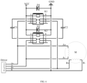
- the two-phase stepper motor assembly in this embodiment includes a motor driver, referred as Driver, two switch units in an automatic transfer switch K1, two capacitive loads (a capacitive load C1 and a capacitive load C2), and a two-phase stepper motor M.
- a normally closed terminal 2 of one of the two switch units in the automatic transfer switch K1 is connected to one terminal of the capacitive load C1, the other terminal of the capacitive load C1 is connected to a terminal A- of the motor driver, referred as Driver, and the terminal A- of the motor driver, referred as Driver is also connected to a terminal A- of the windings of the two-phase motor M.
- a normally closed terminal 7 of one of the two switch units in the automatic transfer switch K1 is connected to one terminal of the capacitive load C2, the other terminal of the capacitive load C2 is connected to a terminal B+ of the motor driver, referred as Driver, and the terminal B+ of the motor driver, referred as Driver is also connected to a terminal B+ of the windings of the two-phase motor M.
- a common terminal 3 of one of the two switch units in the automatic transfer switch K1 is connected to a terminal A+ of the windings of the two-phase motor M
- a common terminal 6 of the other of the two switch units in the automatic transfer switch K1 is connected to a terminal B- of the windings of the two-phase motor M.
- a normally opened terminal 4 of one of the two switch units in the automatic transfer switch K1 is connected to a terminal A+ of the motor driver, referred as Driver
- a normally opened terminal 5 of the other of the two switch units in the automatic transfer switch K1 is connected to a terminal B- of the motor driver, referred as Driver.
- FIG. 4 illustrates only one of the connection methods, and this embodiment discloses a total of four connection methods, which are not listed here.
- the components fall under gravity to drive the two-phase motor M to rotate.
- the induced electromotive force generated by the rotation of the two-phase motor M is an alternating current.
- the capacitive load has an alternating current isolation effect.
- the windings of the two-phase motor M are capable of generating an induced current, such that the two-phase motor M generates an electromagnetic torque with a braking effect.
- the motor assembly is a three-phase motor assembly in this embodiment.
- the three-phase motor assembly includes a motor driver, two automatic transfer switches, three capacitive loads, and a three-phase motor. It should be noted that in this embodiment, each of the two automatic transfer switches includes a switch unit. Therefore, this embodiment includes two switch units.
- Output terminals of the motor driver are connected to normally opened terminals of the two switch units, common terminals of the two switch units are connected to two windings of the three-phase motor, totally six terminals of the three capacitive loads are connected in sequence in a ring pattern, normally closed terminals of the two switch units are respectively connected to two terminals of one of the three capacitive loads, and the remaining output terminal of the motor driver and the remaining winding of the three-phase motor are connected to the remaining terminal of the capacitive load.
- three terminals of the three capacitive loads are connected to each other in a radial pattern, the normally closed terminals of the two switch units are respectively connected to the other terminals of the two of the three capacitive loads, and the remaining output terminal and the remaining winding of the three-phase motor are connected to the other terminal of the remaining one of the three capacitive loads.
- the three-phase stepper motor assembly in this embodiment includes a motor driver, referred as Driver, a switch unit in an automatic transfer switch K1, a switch unit in an automatic transfer switch K2, three capacitive loads (a capacitive load C1, a capacitive load C2, and a capacitive load C3), and a three-phase stepper motor M.
- Driver a motor driver
- switch unit in an automatic transfer switch K1 a switch unit in an automatic transfer switch K2
- three capacitive loads a capacitive load C1, a capacitive load C2, and a capacitive load C3
- a normally opened terminal 5 of the switch unit in the automatic transfer switch K1 is connected to a terminal A-IN of the motor driver, referred as Driver
- a normally opened terminal 5 of the switch unit in the automatic transfer switch K2 is connected to a terminal B-IN of the motor driver, referred as Driver
- a terminal C-IN of the motor driver, referred as Driver is connected to a terminal C of the windings of the three-phase motor M.
- a common terminal 3 (A OUT) of the switch unit in the automatic transfer switch K1 is connected to a terminal A of the windings of the three-phase motor M
- a common terminal 3 (B OUT) of the switch unit in the automatic transfer switch K2 is connected to a terminal B of the windings of the two-phase motor M.
- a normally closed terminal 4 of the switch unit in the automatic transfer switch K 1 and a normally closed terminal 4 of the switch unit in the automatic transfer switch K2 are connected to two terminals of the capacitive load C1, the normally closed terminal 4 of the switch unit in the automatic transfer switch K2 and the terminal C-IN of the motor driver, referred as Driver are connected to two terminals of the capacitive load C2, and the normally closed terminal 4 of the switch unit in the automatic transfer switch K1 and the terminal C-IN of the motor driver, referred as Driver are connected to two terminals of the capacitive load C3.
- the normally closed terminal 4 of the switch unit in the automatic transfer switch K1 and the normally closed terminal 4 of the switch unit in the automatic transfer switch K2 are pairwise connected to two terminals of the capacitive load C1
- the normally closed terminal 4 of the switch unit in the automatic transfer switch K2 and the terminal C-IN of the motor driver, referred as Driver are pairwise connected to two terminals of the capacitive load C2
- the normally closed terminal 4 of the switch unit in the automatic transfer switch K1 and the terminal C-IN of the motor driver referred as Driver are pairwise connected to two terminals of the capacitive load C3.
- two terminals of the capacitive load C1, two terminals of the capacitive load C2, and two terminals of the capacitive load C3 are connected in sequence in a ring pattern
- the normally closed terminal of the switch unit in the automatic transfer switch K1 and the normally closed terminal of the switch unit in the automatic transfer switch K2 are respectively connected to two terminals of one of the three capacitive loads
- the remaining output terminal of the motor driver and the remaining winding of the three-phase motor are connected to totally four terminals of the remaining two of the three capacitive loads.
- one terminal of the capacitive load C1, one terminal of the capacitive load C2, and one terminal of the capacitive load C3 are connected to each other in a radial pattern
- the normally closed terminal of the switch unit in the automatic transfer switch K1 and the normally closed terminal of the switch unit in the automatic transfer switch K2 are respectively connected to the other terminals of two of the three capacitive loads
- the remaining output terminal of the motor driver and the remaining winding of the three-phase motor are connected to the other terminal of the remaining one of the three capacitive loads.
- circuit operation of the three-phase stepper motor assembly in this embodiment is the same as the circuit operation of the two-phase stepper motor assembly, which is thus not described herein any further.
- each of the automatic transfer switches in the motor assembly includes one or more switch units.
- Each switch unit includes a common terminal and a normally closed terminal. The windings of the alternating current motor are directly connected to corresponding terminals of the motor driver and further connected to the common terminal, and the normally closed terminal is connected to the capacitive load.
- the normally closed terminal of the corresponding switch unit is connected to two terminals of the corresponding capacitive load corresponding to the winding.
- the motor assembly is a two-phase motor assembly in this embodiment.
- the two-phase motor assembly includes a motor driver, two automatic transfer switches, two capacitive loads, and a two-phase motor.
- each of the two automatic transfer switch includes two switch units. Therefore, this embodiment includes four switch units. Common terminals of the four switch units are connected to two terminals of two windings of the two-phase motor, and two output terminals of the drive motor corresponding to the windings. Normally closed terminals of the two switch units connected to the same winding are respectively connected to two terminals of one of the two capacitive loads.
- the two-phase stepper motor assembly in this embodiment includes a motor driver, referred as Driver, two switch units in an automatic transfer switch K1, two switch units in an automatic transfer switch K2, two capacitive loads (a capacitive load C1 and a capacitive load C2), and a two-phase motor M.
- Driver a motor driver
- two switch units in an automatic transfer switch K1 two switch units in an automatic transfer switch K2
- two capacitive loads a capacitive load C1 and a capacitive load C2
- M two-phase motor M.
- a terminal A+ of the windings of the two-phase motor M is connected to a terminal A+ of the motor driver, referred as Driver and further connected to a common terminal 3 of one of the two switch units in the automatic transfer switch K1, and a terminal B+ of the windings of the two-phase motor M is connected to a terminal B+ of the motor driver, referred as Driver and further connected to a common terminal 6 of the other of the two switch units in the automatic transfer switch K1.
- a terminal A- of the windings of the two-phase motor M is connected to a terminal A- of the motor driver, referred as Driver and further connected to a common terminal 3 of one of the two switch units in the automatic transfer switch K2, and a terminal B- of the windings of the two-phase motor M is connected to a terminal B- of the motor driver, referred as Driver and further connected to a common terminal 6 of the other of the two switch units in the automatic transfer switch K2. It should be noted that it is feasible that each winding corresponds to the two switch units in one automatic transfer switch, instead of crossing each other.
- a normally closed terminal 2 of one of the two switch units in the automatic transfer switch K1 and a normally closed terminal 2 of one of the two switch units in the automatic transfer switch K2 are connected to two terminals of the capacitive load C1.
- a normally closed terminal 7 of one of the two switch units in the automatic transfer switch K1 and a normally closed terminal 7 of one of the two switch units in the automatic transfer switch K2 are connected to two terminals of the capacitive load C2.
- the power supply is supplying power or the switch unit outputs a coil pull-in signal
- the coils of the two switch units in the automatic transfer switch K1 are pulled-in
- the coils of the two switch units in the automatic transfer switch K2 are pulled-in, and the four switch units are opened.
- the output terminals of the motor driver, referred as Driver are directly connected to the windings of the two-phase motor M and further connected to the common terminals of the four switch units; and the two-phase motor M operates according to the output signals of the motor driver, referred as Driver.
- the coils of the relays are powered down, the relays are at a normally closed contact, and the windings of the motor are connected to two terminals of the capacitor.
- the components fall under gravity to drive the two-phase motor M to rotate.
- the induced electromotive force generated by the rotation of the motor is an alternating current.
- the capacitive load has an alternating current isolation effect.
- the windings of the motor are capable of generating an induced current, such that the motor generates an electromagnetic torque with a braking effect.
- the windings of the two-phase motor M are connected to two terminals of the capacitive load C1 and two terminals of the capacitive load C2.
- the components fall under gravity to drive the two-phase motor M to rotate.
- the induced electromotive force generated by the rotation of the two-phase motor M is an alternating current.
- the capacitive load has an alternating current isolation effect.
- the windings of the two-phase motor M are capable of generating an induced current, such that the two-phase motor M generates an electromagnetic torque with a braking effect.
- the circuit is equivalent to a rectifier bridge circuit composed of only freewheeling diodes, the alternating current induced electromotive force generated by the two-phase motor M becomes a direct current in case of traveling through the rectifier bridge, and the front terminal of the motor driver, referred as Driver is only connected to some capacitive loads with a small capacity.
- the capacitive load is fully charged by the induced electricity generated at the moment of the power failure, a complete current loop fails to be formed with circuit of the motor driver, referred as Driver. Therefore, the induced current generated by the two-phase motor M will only be connected to the loop of the capacitors via the normally closed terminals of the relays.
- the motor assembly is a three-phase motor assembly in ths embodiment.
- the three-phase motor assembly includes a motor driver, three automatic transfer switches, three capacitive loads, and a three-phase motor. It should be noted that in this embodiment, each of the three automatic transfer switches includes a switch unit. Therefore, the three-phase motor assembly according to this embodiment includes a motor driver, three switch units, three capacitive loads, and a three-phase motor.
- Common terminals of the three switch units are connected to three windings of the three-phase motor and output terminals of the motor driver corresponding to the three windings, totally six terminals of the three capacitive loads are connected in sequence in a ring pattern, and each pair of normally closed terminals of the three switch units is connected to two terminals of each of the capacitive loads.
- the three-phase stepper motor assembly in this embodiment includes a motor driver, referred as Driver, a switch unit in an automatic transfer switch K1, a switch unit in an automatic transfer switch K2, a switch unit in an automatic transfer switch K3, three capacitive loads (a capacitive load C1, a capacitive load C2, and a capacitive load C3), and a three-phase stepper motor M.
- Driver a motor driver
- switch unit in an automatic transfer switch K1 a switch unit in an automatic transfer switch K2
- a switch unit in an automatic transfer switch K3 three capacitive loads (a capacitive load C1, a capacitive load C2, and a capacitive load C3)
- a three-phase stepper motor M referred as Driver
- a terminal A-IN of the motor driver referred as Driver is connected to a terminal A of the windings of the three-phase motor M and further connected to a common terminal 3 (A OUT) of the switch unit in the automatic transfer switch K1
- a terminal B-IN of the motor driver referred as Driver is connected to a terminal B of the windings of the three-phase motor M and further connected to a common terminal 3 (B OUT) of the switch unit in the automatic transfer switch K2
- a terminal C-IN of the motor driver referred as Driver is connected to a terminal C of the windings of the three-phase motor M and further connected to a common terminal 3 (C OUT) of the switch unit in the automatic transfer switch K3.
- a normally closed terminal 4 of the switch unit in the automatic transfer switch K1 and a normally closed terminal 4 of the switch unit in the automatic transfer switch K2 are connected to two terminals of the capacitive load C1
- the normally closed terminal 4 of the switch unit in the automatic transfer switch K2 and a normally closed terminal 4 of the switch unit in the automatic transfer switch K3 are connected to two terminals of the capacitive load C2
- the normally closed terminal 4 of the switch unit in the automatic transfer switch K1 and the normally closed terminal 4 of the switch unit in the automatic transfer switch K3 are connected to two terminals of the capacitive load C3.
- the normally closed terminal 4 of the switch unit in the automatic transfer switch K1 and the normally closed terminal 4 of the switch unit in the automatic transfer switch K2 are pairwise connected to two terminals of the capacitive load C1
- the normally closed terminal 4 of the switch unit in the automatic transfer switch K2 and the normally closed terminal 4 of the switch unit in the automatic transfer switch K3 are pairwise connected to two terminals of the capacitive load C2
- the normally closed terminal 4 of the switch unit in the automatic transfer switch K1 and the normally closed terminal 4 of the switch unit in the automatic transfer switch K3 are pairwise connected to two terminals of the capacitive load C3.
- two terminals of the capacitive load C1, two terminals of the capacitive load C2, and two terminals of the capacitive load C3 are connected in sequence in a ring pattern, and the normally closed terminal of the switch unit in the automatic transfer switch K1, the normally closed terminal of the switch unit in the automatic transfer switch K2, and the normally closed terminal of the switch unit in the automatic transfer switch K3 are respectively pairwise connected to two terminals one of the capacitive loads.
- circuit operation of the three-phase stepper motor assembly in this embodiment is the same as the circuit operation of the two-phase stepper motor assembly, which is thus not described herein any further.
- the motor assembly is a three-phase motor assembly in this embodiment.
- the three-phase motor assembly includes a motor driver, three automatic transfer switches, three capacitive loads, and a three-phase motor. It should be noted that in this embodiment, each of the three automatic transfer switches includes a switch unit. Therefore, the three-phase motor assembly according to this embodiment includes a motor driver, three switch units, three capacitive loads, and a three-phase motor.
- Output terminals of the motor driver are connected to common terminals of the three switch units, the common terminals of the three switch units are further connected to three windings of the three-phase motor, three terminals of the three capacitive loads are connected to each other in a radial pattern, and each of normally closed terminals of the three switch units is connected to the other terminal of one of the capacitive loads.
- the three-phase stepper motor assembly in this embodiment includes a motor driver, referred as Driver, a switch unit in an automatic transfer switch K1, a switch unit in an automatic transfer switch K2, a switch unit in an automatic transfer switch K3, three capacitive loads (a capacitive load C1, a capacitive load C2, and a capacitive load C3), and a three-phase stepper motor M.
- Driver a motor driver
- switch unit in an automatic transfer switch K1 a switch unit in an automatic transfer switch K2
- a switch unit in an automatic transfer switch K3 three capacitive loads (a capacitive load C1, a capacitive load C2, and a capacitive load C3)
- a three-phase stepper motor M referred as Driver
- a terminal A-IN of the motor driver referred as Driver is connected to a terminal A of the windings of the three-phase motor M and further connected to a common terminal 3 (A OUT) of the switch unit in the automatic transfer switch K1
- a terminal B-IN of the motor driver referred as Driver is connected to a terminal B of the windings of the three-phase motor M and further connected to a common terminal 3 (B OUT) of the switch unit in the automatic transfer switch K2
- a terminal C-IN of the motor driver referred as Driver is connected to a terminal C of the windings of the three-phase motor M and further connected to a common terminal 3 (C OUT) of the switch unit in the automatic transfer switch K3.
- a normally closed terminal 4 of the switch unit in the automatic transfer switch K1 is connected to one terminal of the capacitive load C1, and the other terminal of the capacitive load C1 is connected to one terminal of the capacitive load C2 and one terminal of the capacitive load C3.
- a normally closed terminal 4 of the switch unit in the automatic transfer switch K2 is connected to one terminal of the capacitive load C2, and the other terminal of the capacitive load C2 is connected to one terminal of the capacitive load C1 and one terminal of the capacitive load C3.
- a normally closed terminal 4 of the switch unit in the automatic transfer switch K3 is connected to one terminal of the capacitive load C3, and the other terminal of the capacitive load C3 is connected to one terminal of the capacitive load C1 and one terminal of the capacitive load C2.
- the normally closed terminal 4 of the switch unit in the automatic transfer switch K1 and the normally closed terminal 4 of the switch unit in the automatic transfer switch K2 are pairwise connected to one terminal of the capacitive load C1 and one terminal of the capacitive load C2, and the other terminal of the capacitive load C1 and the other terminal of the capacitive load C2 are connected to each other.
- the normally closed terminal 4 of the switch unit in the automatic transfer switch K1 and the normally closed terminal 4 of the switch unit in the automatic transfer switch K3 are pairwise connected to one terminal of the capacitive load C1 and one terminal of the capacitive load C3, and the other terminal of the capacitive load C1 and the other terminal of the capacitive load C3 are connected to each other.
- the normally closed terminal 4 of the switch unit in the automatic transfer switch K2 and the normally closed terminal 4 of the switch unit in the automatic transfer switch K3 are pairwise connected to one terminal of the capacitive load C2 and one terminal of the capacitive load C3, and the other terminal of the capacitive load C2 and the other terminal of the capacitive load C3 are connected to each other.
- one terminal of the capacitive load C1, one terminal of the capacitive load C2, and one terminal of the capacitive load C3 are connected to each other in a radial pattern, and each of the normally closed terminal of the switch unit in the automatic transfer switch K1, the normally closed terminal of the switch unit in the automatic transfer switch K2, and the normally closed terminal of the switch unit in the automatic transfer switch K3 is connected to the other terminal of one of the capacitive loads.
- circuit operation of the three-phase stepper motor assembly in this embodiment is the same as the circuit operation of the two-phase stepper motor assembly, which is thus not described herein any further.
- one terminal of at least one of the windings of the alternating current motor is connected to one corresponding output terminal of the motor driver and further connected to the common terminal of the corresponding switch unit, one terminal of the capacitive load is connected to the normally closed terminal of the corresponding switch unit, and the other terminal of the capacitive load is connected to the output terminal of the motor driver or the normally closed terminal of another switch unit.
- the motor assembly is a two-phase motor assembly in this embodiment.
- the two-phase motor assembly includes a motor driver, one automatic transfer switch, two capacitive loads, and a two-phase motor.
- the automatic transfer switch includes two switch units. Therefore, the two-phase motor assembly according to this embodiment includes a motor driver, two switch units, two capacitive loads, and a two-phase motor.
- Each terminal of the motor driver is connected to one terminal of one of the windings and connected to the common terminal of one of the two switch units, the normally closed terminals of the corresponding switch units are respectively connected to two terminals of the two capacitive loads, and the other terminals of the two capacitive loads are respectively connected to two output terminals of the motor driver.
- the two-phase stepper motor assembly in this embodiment includes a motor driver, referred as Driver, two switch units in an automatic transfer switch K1, two capacitive loads (a capacitive load C1 and a capacitive load C2), and a two-phase motor M.
- a normally closed terminal 2 of one of the two switch units in the automatic transfer switch K1 is connected to one terminal of the capacitive load C1, the other terminal of the capacitive load C1 is connected to a terminal A- of the motor driver, referred as Driver, and the terminal A- of the motor driver, referred as Driver is also connected to a terminal A- of the windings of the two-phase motor M.
- a normally closed terminal 7 of one of the two switch units in the automatic transfer switch K1 is connected to one terminal of the capacitive load C2, the other terminal of the capacitive load C2 is connected to a terminal B+ of the motor driver, referred as Driver, and the terminal B+ of the motor driver, referred as Driver is also connected to a terminal B+ of the windings of the two-phase motor M.
- a common terminal 3 of one of the two switch units in the automatic transfer switch K1 is connected to a terminal A+ of the winding of the two-phase motor M, and a common terminal 6 of one of the two switch units in the automatic transfer switch K1 is connected to a terminal B- of the winding of the two-phase motor M.
- a common terminal 3 of one of the two switch units in the automatic transfer switch K1 is further connected to a terminal A+ of the motor driver, referred as Driver, and a common terminal 3 of the other of the two switch units in the automatic transfer switch K1 is further connected to a terminal B- of the motor driver, referred as Driver.
- FIG. 9 illustrates only one of the connection methods, and this embodiment has a total of four connection methods, which are not listed here.
- the components fall under gravity to drive the two-phase motor M to rotate.
- the induced electromotive force generated by the rotation of the two-phase motor M is an alternating current.
- the capacitive load has an alternating current isolation effect.
- the windings of the two-phase motor M are capable of generating an induced current, such that the two-phase motor M generates an electromagnetic torque with a braking effect.
- the motor assembly is a three-phase motor assembly in this embodiment.
- the three-phase motor assembly includes a motor driver, two automatic transfer switches, three capacitive loads, and a three-phase motor. It should be noted that in this embodiment, each of the two automatic transfer switches includes a switch unit. Therefore, the three-phase motor assembly according to this embodiment includes a motor driver, two switch units, three capacitive loads, and a three-phase motor.
- Output terminals of the motor driver are connected to common terminals of the two switch units, the common terminals of the two switch units are further connected to two windings of the three-phase motor, totally six terminals of the three capacitive loads are connected in sequence in a ring pattern, normally closed terminals of the two switch units are respectively connected to two terminals of one of the three capacitive loads, and the remaining output terminal of the motor driver and the remaining winding of the three-phase motor are connected to the remaining terminal of the capacitive load.
- three terminals of the three capacitive loads are connected to each other in a radial pattern, the normally closed terminals of the two switch units are respectively connected to the other terminals of the two of the three capacitive loads, and the remaining output terminal and the remaining winding of the three-phase motor are connected to the other terminal of the remaining one of the three capacitive loads.
- the three-phase stepper motor assembly in this embodiment includes a motor driver, referred as Driver, a switch unit in an automatic transfer switch K1, a switch unit in an automatic transfer switch K2, three capacitive loads (a capacitive load C1, a capacitive load C2, and a capacitive load C3), and a three-phase stepper motor M.
- Driver a motor driver
- switch unit in an automatic transfer switch K1 a switch unit in an automatic transfer switch K2
- three capacitive loads a capacitive load C1, a capacitive load C2, and a capacitive load C3
- a terminal A-IN of the motor driver referred as Driver is connected to a terminal A of the windings of the three-phase motor M and further connected to a common terminal 3 (A OUT) of the switch unit in the automatic transfer switch K1
- a terminal B-IN of the motor driver referred as Driver is connected to a terminal B of the windings of the three-phase motor M and further connected to a common terminal 3 (B OUT) of the switch unit in the automatic transfer switch K2
- a terminal C-IN of the motor driver referred as Driver is connected to a terminal C of the windings of the three-phase motor M.
- a normally closed terminal 4 of the switch unit in the automatic transfer switch K1 and a normally closed terminal 4 of the switch unit in the automatic transfer switch K2 are connected to two terminals of the capacitive load C1, the normally closed terminal 4 of the switch unit in the automatic transfer switch K2 and the terminal C-IN of the motor driver, referred as Driver are connected to two terminals of the capacitive load C2, and the normally closed terminal 4 of the switch unit in the automatic transfer switch K1 and the terminal C-IN of the motor driver, referred as Driver are connected to two terminals of the capacitive load C3.
- the normally closed terminal 4 of the switch unit in the automatic transfer switch K1 and the normally closed terminal 4 of the switch unit in the automatic transfer switch K2 are pairwise connected to two terminals of the capacitive load C1
- the normally closed terminal 4 of the switch unit in the automatic transfer switch K2 and the terminal C-IN of the motor driver, referred as Driver are pairwise connected to two terminals of the capacitive load C2
- the normally closed terminal 4 of the switch unit in the automatic transfer switch K1 and the terminal C-IN of the motor driver referred as Driver are pairwise connected to two terminals of the capacitive load C3.
- two terminals of the capacitive load C1, two terminals of the capacitive load C2, and two terminals of the capacitive load C3 are connected in sequence in a ring pattern, the normally closed terminal of the switch unit in the automatic transfer switch K1 and the normally closed terminal of the switch unit in the automatic transfer switch K2 are connected to two terminals of one of the three capacitive loads, and the remaining output terminal of the motor driver and the remaining winding of the three-phase motor are connected to totally four terminals of the remaining two of the three capacitive loads; or
- one terminal of the capacitive load C1, one terminal of the capacitive load C2, and one terminal of the capacitive load C3 are connected to each other in a radial pattern
- the normally closed terminal of the switch unit in the automatic transfer switch K1 and the normally closed terminal of the switch unit in the automatic transfer switch K2 are respectively connected to the other terminals of two of the three capacitive loads
- the remaining output terminal of the motor driver and the remaining winding of the three-phase motor are connected to the other terminal of the remaining one of the three capacitive loads.
- circuit operation of the three-phase stepper motor assembly in this embodiment is the same as the circuit operation of the two-phase stepper motor assembly, which is thus not described herein any further.
- any one of the 10 stepper motors (four two-phase stepper motors and six three-phase stepper motors) according to the above-mentioned embodiments is applicable to a scenario of a power failure of the stage light fixture, and any one of the 10 stepper motors is capable of reducing the falling speed of the stage light fixture in case of the power failure.
- the motor assembly in these embodiments includes a motor driver, an automatic transfer switch, a capacitive load, and an alternating current motor.
- the automatic transfer switch is energized, windings of the alternating current motor are kept connected to the motor driver, and in the case that the automatic transfer switch is deenergized, the windings of the alternating current motor are switched to be connected to the capacitive load.
- two terminals of the windings are connected via a capacitive load, and the capacitive load makes the phase of the induced current 90° ahead of the phase of the induced voltage.
- the directions of the electromotive forces generated by the armature magnetic field of the motor and the primary magnetic field of the permanent magnet are thus consistent, and a longitudinal magnetization armature reaction may be generated.
- the magnetic flux increases, the induced voltage rises, the induced current rises, and the braking torque increases, thereby achieving to reduce the falling speed of the stage light fixture in case of the power failure.
- a stage light fixture is further provided according to one embodiment of the present disclosure.
- the stage light fixture includes the motor assembly for reducing the falling speed of the stage light fixture on power failure.
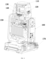
- the stage light fixture includes a light head 110.
- the light head 110 is provided with a light source for generating a light beam, and an effect apparatus for intercepting the light beam to create a light effect.
- the motor assembly drives the effect apparatus to move along a light path or swing or rotate relative to the light path.
- One of the a focus lens 120 or a magnify lens 130 is movable with respect to the optical lens.
- One of a prism 140, an frosting lens, a fixed pattern wheel, a rotary pattern wheel, a color wheel, a fire wheel, an aperture, or a shader 150 is swingable or rotatable with respect to the optical path.
- the stage light fixture includes a support arm 160 for supporting rotation of the light head 110, and a case 170 configured for supporting rotation of the arm.
- the motor driver drives the light head 110 to rotate with respect to the support arm 160 and/or drives the support arm 160 to rotate with respect to the cabinet 170.
- the motor assembly according to the present disclosure reduces the falling speed of the stage light fixture in case of the power failure. In this way, the impact force generated due to falling of the stage light fixture on power failure is reduced, and the components of the stage light fixture are thus better protected.
- a focus lens driven by a single stepper motor is provided, which lens is provided with a plurality of frosting and prism motors, and the overall weight thereof is relatively large.
- the lens may quickly fall when power failure, components short-circuited by the windings of the motor may also fall quickly, and the braking torque is insufficient.
- the motor assembly according to the present disclosure can slow down the falling speed of the stage light fixture on power failure, and the falling speed of the focus lens is effectively reduced.
Landscapes
- Engineering & Computer Science (AREA)
- General Engineering & Computer Science (AREA)
- Power Engineering (AREA)
- Control Of Ac Motors In General (AREA)
Applications Claiming Priority (2)
| Application Number | Priority Date | Filing Date | Title |
|---|---|---|---|
| CN202211213403.5A CN115483852B (zh) | 2022-09-29 | 2022-09-29 | 减缓舞台灯具掉电后跌落速度的电机组件及舞台灯具 |
| CN202223411086.6U CN219124064U (zh) | 2022-12-15 | 2022-12-15 | 一种减缓舞台灯具掉电后跌落速度的电机组件 |
Publications (1)
| Publication Number | Publication Date |
|---|---|
| EP4346084A1 true EP4346084A1 (de) | 2024-04-03 |
Family
ID=84767001
Family Applications (1)
| Application Number | Title | Priority Date | Filing Date |
|---|---|---|---|
| EP22217369.2A Pending EP4346084A1 (de) | 2022-09-29 | 2022-12-30 | Motoranordnung zur verlangsamung der fallgeschwindigkeit einer bühnenleuchte bei stromausfall und bühnenleuchte |
Country Status (2)
| Country | Link |
|---|---|
| US (1) | US12308778B2 (de) |
| EP (1) | EP4346084A1 (de) |
Families Citing this family (1)
| Publication number | Priority date | Publication date | Assignee | Title |
|---|---|---|---|---|
| CN120729096B (zh) * | 2025-08-15 | 2026-01-06 | 合肥卓骏汽车科技有限公司 | 一种非自锁电机的速度控制系统及方法 |
Citations (4)
| Publication number | Priority date | Publication date | Assignee | Title |
|---|---|---|---|---|
| JPS60135097U (ja) * | 1984-02-16 | 1985-09-07 | 株式会社明電舎 | 誘導電動機の制御回路 |
| JPH02277560A (ja) * | 1989-01-18 | 1990-11-14 | Sharp Corp | 書類細断装置 |
| EP1520829A1 (de) * | 2002-07-10 | 2005-04-06 | Mitsubishi Denki Kabushiki Kaisha | Steuerung für aufzug |
| US20100066282A1 (en) * | 2006-10-31 | 2010-03-18 | Knorr-Bremse Systeme Fur Schienenfahrzeuge Gmbh | Traction drive of a rail vehicle for driving and generative braking with load correction |
Family Cites Families (8)
| Publication number | Priority date | Publication date | Assignee | Title |
|---|---|---|---|---|
| US3618202A (en) * | 1969-05-12 | 1971-11-09 | Mallory & Co Inc P R | Ceramic chip electrical components |
| JPH0459586A (ja) * | 1990-06-29 | 1992-02-26 | Mitsubishi Electric Corp | エレベータのドア制御装置 |
| US5218283A (en) * | 1991-02-15 | 1993-06-08 | York International Corporation | AC motor drive system with a two phase power supply |
| CZ17567U1 (cs) | 2005-11-08 | 2007-06-11 | Martin Professional A/S | Brzdný systém pro pohyb sestav svítidel |
| CN201004613Y (zh) | 2007-01-26 | 2008-01-09 | 武汉理工大学 | 电动机柔性软制动器 |
| DK2639449T3 (en) | 2012-03-15 | 2016-03-21 | Siemens Ag | Electrical yaw drive for a wind turbine, the wind turbine and method for operating a wind turbine |
| PL3427378T3 (pl) | 2016-03-11 | 2024-01-29 | Karl Dungs Gmbh & Co.Kg | Zaworowy napęd nastawczy i sposób jego eksploatacji |
| US10274175B1 (en) * | 2018-01-04 | 2019-04-30 | Electronic Theatre Controls, Inc. | Systems and methods for controlling the position of a moving light fixture |
-
2022
- 2022-12-30 US US18/091,847 patent/US12308778B2/en active Active
- 2022-12-30 EP EP22217369.2A patent/EP4346084A1/de active Pending
Patent Citations (4)
| Publication number | Priority date | Publication date | Assignee | Title |
|---|---|---|---|---|
| JPS60135097U (ja) * | 1984-02-16 | 1985-09-07 | 株式会社明電舎 | 誘導電動機の制御回路 |
| JPH02277560A (ja) * | 1989-01-18 | 1990-11-14 | Sharp Corp | 書類細断装置 |
| EP1520829A1 (de) * | 2002-07-10 | 2005-04-06 | Mitsubishi Denki Kabushiki Kaisha | Steuerung für aufzug |
| US20100066282A1 (en) * | 2006-10-31 | 2010-03-18 | Knorr-Bremse Systeme Fur Schienenfahrzeuge Gmbh | Traction drive of a rail vehicle for driving and generative braking with load correction |
Also Published As
| Publication number | Publication date |
|---|---|
| US20240113640A1 (en) | 2024-04-04 |
| US12308778B2 (en) | 2025-05-20 |
Similar Documents
| Publication | Publication Date | Title |
|---|---|---|
| US8093764B2 (en) | Method and system for bypassing a power cell of a power supply | |
| US6037740A (en) | Switched reluctance electric machine system | |
| EP1520829A1 (de) | Steuerung für aufzug | |
| US10608509B2 (en) | Rotatable electric machines | |
| EP1975960A1 (de) | Bistabiler magnetischer Betätiger, elektronischer Steuerkreis und Verfahren zum Betreiben eines solchen Betätigers. | |
| CA3045839A1 (en) | Short-circuit braking of an llm | |
| KR101449736B1 (ko) | 컨버터의 바이패스 장치 | |
| EP0733578B1 (de) | Notbetriebsvorrichtung für Aufzugsmotor | |
| EP4346084A1 (de) | Motoranordnung zur verlangsamung der fallgeschwindigkeit einer bühnenleuchte bei stromausfall und bühnenleuchte | |
| US6713984B1 (en) | Operating device for driving and controlling an electrical switching apparatus | |
| US8390236B2 (en) | Drive system for operating an electric device | |
| US10366854B2 (en) | Contactor with coil polarity reversing control circuit | |
| EP3376519B1 (de) | Schaltgerät für mittelspannungsenergieverteilungsinstallationen | |
| KR20140115666A (ko) | 컨버터의 바이패스 스위치 장치 | |
| US20190074784A1 (en) | Rotatable electric machines | |
| CN219124064U (zh) | 一种减缓舞台灯具掉电后跌落速度的电机组件 | |
| JP6252448B2 (ja) | 開閉器および電力変換装置 | |
| US7498756B2 (en) | Braking system for electric step motors | |
| CN115483852B (zh) | 减缓舞台灯具掉电后跌落速度的电机组件及舞台灯具 | |
| RU2075819C1 (ru) | Электропривод | |
| CA2225749C (en) | Switched reluctance electric machine system | |
| US945103A (en) | Motor-control system. | |
| RU2722793C1 (ru) | Устройство генерации электроэнергии | |
| JPH01117674A (ja) | モータの制動装置 | |
| RU2020115909A (ru) | Управление генератором методом подключения и отключения генераторных обмоток |
Legal Events
| Date | Code | Title | Description |
|---|---|---|---|
| PUAI | Public reference made under article 153(3) epc to a published international application that has entered the european phase |
Free format text: ORIGINAL CODE: 0009012 |
|
| STAA | Information on the status of an ep patent application or granted ep patent |
Free format text: STATUS: REQUEST FOR EXAMINATION WAS MADE |
|
| 17P | Request for examination filed |
Effective date: 20230123 |
|
| AK | Designated contracting states |
Kind code of ref document: A1 Designated state(s): AL AT BE BG CH CY CZ DE DK EE ES FI FR GB GR HR HU IE IS IT LI LT LU LV MC ME MK MT NL NO PL PT RO RS SE SI SK SM TR |
|
| STAA | Information on the status of an ep patent application or granted ep patent |
Free format text: STATUS: EXAMINATION IS IN PROGRESS |
|
| 17Q | First examination report despatched |
Effective date: 20250826 |