EP1520914B1 - Anlage zum Beschichten von Werkstücken durch Elektronenstrahlen - Google Patents
Anlage zum Beschichten von Werkstücken durch Elektronenstrahlen Download PDFInfo
- Publication number
- EP1520914B1 EP1520914B1 EP03293346A EP03293346A EP1520914B1 EP 1520914 B1 EP1520914 B1 EP 1520914B1 EP 03293346 A EP03293346 A EP 03293346A EP 03293346 A EP03293346 A EP 03293346A EP 1520914 B1 EP1520914 B1 EP 1520914B1
- Authority
- EP
- European Patent Office
- Prior art keywords
- coated
- work pieces
- chamber
- crucibles
- coating
- Prior art date
- Legal status (The legal status is an assumption and is not a legal conclusion. Google has not performed a legal analysis and makes no representation as to the accuracy of the status listed.)
- Expired - Lifetime
Links
- 238000000576 coating method Methods 0.000 title claims description 82
- 238000009434 installation Methods 0.000 title claims description 43
- 239000011248 coating agent Substances 0.000 title claims description 39
- 238000010894 electron beam technology Methods 0.000 title claims description 26
- 239000000463 material Substances 0.000 claims description 23
- 238000009834 vaporization Methods 0.000 claims description 16
- 238000001816 cooling Methods 0.000 claims description 4
- 239000010410 layer Substances 0.000 description 33
- 238000000151 deposition Methods 0.000 description 30
- 230000008021 deposition Effects 0.000 description 21
- 229910052710 silicon Inorganic materials 0.000 description 20
- 229910052751 metal Inorganic materials 0.000 description 16
- 239000002184 metal Substances 0.000 description 16
- 238000001704 evaporation Methods 0.000 description 15
- XUIMIQQOPSSXEZ-UHFFFAOYSA-N Silicon Chemical compound [Si] XUIMIQQOPSSXEZ-UHFFFAOYSA-N 0.000 description 14
- 238000000034 method Methods 0.000 description 14
- 229910045601 alloy Inorganic materials 0.000 description 13
- 239000000956 alloy Substances 0.000 description 13
- 230000008020 evaporation Effects 0.000 description 13
- 230000008569 process Effects 0.000 description 12
- 229910021332 silicide Inorganic materials 0.000 description 12
- 229910052735 hafnium Inorganic materials 0.000 description 11
- 239000000919 ceramic Substances 0.000 description 10
- 239000007789 gas Substances 0.000 description 10
- 230000015572 biosynthetic process Effects 0.000 description 9
- 239000000203 mixture Substances 0.000 description 9
- 239000012071 phase Substances 0.000 description 9
- FVBUAEGBCNSCDD-UHFFFAOYSA-N silicide(4-) Chemical compound [Si-4] FVBUAEGBCNSCDD-UHFFFAOYSA-N 0.000 description 9
- 230000008016 vaporization Effects 0.000 description 9
- 229910052726 zirconium Inorganic materials 0.000 description 9
- 239000002131 composite material Substances 0.000 description 8
- 150000001875 compounds Chemical class 0.000 description 8
- 238000010438 heat treatment Methods 0.000 description 8
- 239000010703 silicon Substances 0.000 description 8
- 229910052727 yttrium Inorganic materials 0.000 description 8
- 238000010276 construction Methods 0.000 description 7
- 150000002739 metals Chemical class 0.000 description 7
- 239000000126 substance Substances 0.000 description 7
- 239000011253 protective coating Substances 0.000 description 6
- 230000007704 transition Effects 0.000 description 6
- 229910052804 chromium Inorganic materials 0.000 description 5
- 239000011651 chromium Substances 0.000 description 5
- VBJZVLUMGGDVMO-UHFFFAOYSA-N hafnium atom Chemical compound [Hf] VBJZVLUMGGDVMO-UHFFFAOYSA-N 0.000 description 5
- 239000010936 titanium Substances 0.000 description 5
- 229910052719 titanium Inorganic materials 0.000 description 5
- 230000009471 action Effects 0.000 description 4
- 239000000654 additive Substances 0.000 description 4
- 238000004519 manufacturing process Methods 0.000 description 4
- 229910052750 molybdenum Inorganic materials 0.000 description 4
- VYZAMTAEIAYCRO-UHFFFAOYSA-N Chromium Chemical compound [Cr] VYZAMTAEIAYCRO-UHFFFAOYSA-N 0.000 description 3
- 229910019974 CrSi Inorganic materials 0.000 description 3
- MCMNRKCIXSYSNV-UHFFFAOYSA-N ZrO2 Inorganic materials O=[Zr]=O MCMNRKCIXSYSNV-UHFFFAOYSA-N 0.000 description 3
- 238000005566 electron beam evaporation Methods 0.000 description 3
- 239000007791 liquid phase Substances 0.000 description 3
- 210000000056 organ Anatomy 0.000 description 3
- 230000003647 oxidation Effects 0.000 description 3
- 238000007254 oxidation reaction Methods 0.000 description 3
- ZOXJGFHDIHLPTG-UHFFFAOYSA-N Boron Chemical compound [B] ZOXJGFHDIHLPTG-UHFFFAOYSA-N 0.000 description 2
- RYGMFSIKBFXOCR-UHFFFAOYSA-N Copper Chemical compound [Cu] RYGMFSIKBFXOCR-UHFFFAOYSA-N 0.000 description 2
- 229910016006 MoSi Inorganic materials 0.000 description 2
- ZOKXTWBITQBERF-UHFFFAOYSA-N Molybdenum Chemical compound [Mo] ZOKXTWBITQBERF-UHFFFAOYSA-N 0.000 description 2
- RTAQQCXQSZGOHL-UHFFFAOYSA-N Titanium Chemical compound [Ti] RTAQQCXQSZGOHL-UHFFFAOYSA-N 0.000 description 2
- QCWXUUIWCKQGHC-UHFFFAOYSA-N Zirconium Chemical compound [Zr] QCWXUUIWCKQGHC-UHFFFAOYSA-N 0.000 description 2
- 230000000996 additive effect Effects 0.000 description 2
- 229910052796 boron Inorganic materials 0.000 description 2
- 229910052802 copper Inorganic materials 0.000 description 2
- 239000010949 copper Substances 0.000 description 2
- 238000006073 displacement reaction Methods 0.000 description 2
- 230000007246 mechanism Effects 0.000 description 2
- 239000007769 metal material Substances 0.000 description 2
- 238000002360 preparation method Methods 0.000 description 2
- 238000003303 reheating Methods 0.000 description 2
- 239000002356 single layer Substances 0.000 description 2
- 238000002207 thermal evaporation Methods 0.000 description 2
- 238000003466 welding Methods 0.000 description 2
- VWQVUPCCIRVNHF-UHFFFAOYSA-N yttrium atom Chemical compound [Y] VWQVUPCCIRVNHF-UHFFFAOYSA-N 0.000 description 2
- UFHFLCQGNIYNRP-UHFFFAOYSA-N Hydrogen Chemical compound [H][H] UFHFLCQGNIYNRP-UHFFFAOYSA-N 0.000 description 1
- 229910020968 MoSi2 Inorganic materials 0.000 description 1
- 241000135309 Processus Species 0.000 description 1
- 229910008484 TiSi Inorganic materials 0.000 description 1
- 229910006249 ZrSi Inorganic materials 0.000 description 1
- 239000012190 activator Substances 0.000 description 1
- 229910052782 aluminium Inorganic materials 0.000 description 1
- XAGFODPZIPBFFR-UHFFFAOYSA-N aluminium Chemical compound [Al] XAGFODPZIPBFFR-UHFFFAOYSA-N 0.000 description 1
- 238000004458 analytical method Methods 0.000 description 1
- QVGXLLKOCUKJST-UHFFFAOYSA-N atomic oxygen Chemical compound [O] QVGXLLKOCUKJST-UHFFFAOYSA-N 0.000 description 1
- YXTPWUNVHCYOSP-UHFFFAOYSA-N bis($l^{2}-silanylidene)molybdenum Chemical compound [Si]=[Mo]=[Si] YXTPWUNVHCYOSP-UHFFFAOYSA-N 0.000 description 1
- 238000004364 calculation method Methods 0.000 description 1
- 238000005266 casting Methods 0.000 description 1
- 229910021357 chromium silicide Inorganic materials 0.000 description 1
- 238000004140 cleaning Methods 0.000 description 1
- 239000008199 coating composition Substances 0.000 description 1
- 238000009833 condensation Methods 0.000 description 1
- 230000005494 condensation Effects 0.000 description 1
- 230000007797 corrosion Effects 0.000 description 1
- 238000005260 corrosion Methods 0.000 description 1
- 230000007423 decrease Effects 0.000 description 1
- 238000005137 deposition process Methods 0.000 description 1
- 230000006866 deterioration Effects 0.000 description 1
- 238000011161 development Methods 0.000 description 1
- 238000010586 diagram Methods 0.000 description 1
- 238000009792 diffusion process Methods 0.000 description 1
- 238000010494 dissociation reaction Methods 0.000 description 1
- 230000005593 dissociations Effects 0.000 description 1
- 238000009826 distribution Methods 0.000 description 1
- 239000002019 doping agent Substances 0.000 description 1
- 238000005868 electrolysis reaction Methods 0.000 description 1
- -1 for example Substances 0.000 description 1
- 150000004820 halides Chemical class 0.000 description 1
- 239000001257 hydrogen Substances 0.000 description 1
- 229910052739 hydrogen Inorganic materials 0.000 description 1
- 230000006872 improvement Effects 0.000 description 1
- 229910052742 iron Inorganic materials 0.000 description 1
- 238000011068 loading method Methods 0.000 description 1
- 238000011089 mechanical engineering Methods 0.000 description 1
- 238000005272 metallurgy Methods 0.000 description 1
- 238000012986 modification Methods 0.000 description 1
- 230000004048 modification Effects 0.000 description 1
- 239000011733 molybdenum Substances 0.000 description 1
- 229910021344 molybdenum silicide Inorganic materials 0.000 description 1
- 229910052759 nickel Inorganic materials 0.000 description 1
- 229910052758 niobium Inorganic materials 0.000 description 1
- TWNQGVIAIRXVLR-UHFFFAOYSA-N oxo(oxoalumanyloxy)alumane Chemical compound O=[Al]O[Al]=O TWNQGVIAIRXVLR-UHFFFAOYSA-N 0.000 description 1
- 239000001301 oxygen Substances 0.000 description 1
- 229910052760 oxygen Inorganic materials 0.000 description 1
- RVTZCBVAJQQJTK-UHFFFAOYSA-N oxygen(2-);zirconium(4+) Chemical compound [O-2].[O-2].[Zr+4] RVTZCBVAJQQJTK-UHFFFAOYSA-N 0.000 description 1
- 238000007750 plasma spraying Methods 0.000 description 1
- 239000000843 powder Substances 0.000 description 1
- 230000001681 protective effect Effects 0.000 description 1
- 229920006395 saturated elastomer Polymers 0.000 description 1
- 238000004062 sedimentation Methods 0.000 description 1
- 150000003377 silicon compounds Chemical class 0.000 description 1
- 239000011863 silicon-based powder Substances 0.000 description 1
- 239000007787 solid Substances 0.000 description 1
- 229910052596 spinel Inorganic materials 0.000 description 1
- 239000011029 spinel Substances 0.000 description 1
- 239000007921 spray Substances 0.000 description 1
- 239000010935 stainless steel Substances 0.000 description 1
- 229910001220 stainless steel Inorganic materials 0.000 description 1
- 239000007858 starting material Substances 0.000 description 1
- 238000012360 testing method Methods 0.000 description 1
- 230000002024 thermoprotective effect Effects 0.000 description 1
- 229910052721 tungsten Inorganic materials 0.000 description 1
- 238000009489 vacuum treatment Methods 0.000 description 1
- 239000012808 vapor phase Substances 0.000 description 1
- 238000012795 verification Methods 0.000 description 1
- 239000011800 void material Substances 0.000 description 1
- XLYOFNOQVPJJNP-UHFFFAOYSA-N water Substances O XLYOFNOQVPJJNP-UHFFFAOYSA-N 0.000 description 1
Images

Classifications
-
- C—CHEMISTRY; METALLURGY
- C23—COATING METALLIC MATERIAL; COATING MATERIAL WITH METALLIC MATERIAL; CHEMICAL SURFACE TREATMENT; DIFFUSION TREATMENT OF METALLIC MATERIAL; COATING BY VACUUM EVAPORATION, BY SPUTTERING, BY ION IMPLANTATION OR BY CHEMICAL VAPOUR DEPOSITION, IN GENERAL; INHIBITING CORROSION OF METALLIC MATERIAL OR INCRUSTATION IN GENERAL
- C23C—COATING METALLIC MATERIAL; COATING MATERIAL WITH METALLIC MATERIAL; SURFACE TREATMENT OF METALLIC MATERIAL BY DIFFUSION INTO THE SURFACE, BY CHEMICAL CONVERSION OR SUBSTITUTION; COATING BY VACUUM EVAPORATION, BY SPUTTERING, BY ION IMPLANTATION OR BY CHEMICAL VAPOUR DEPOSITION, IN GENERAL
- C23C14/00—Coating by vacuum evaporation, by sputtering or by ion implantation of the coating forming material
- C23C14/06—Coating by vacuum evaporation, by sputtering or by ion implantation of the coating forming material characterised by the coating material
- C23C14/0682—Silicides
-
- C—CHEMISTRY; METALLURGY
- C23—COATING METALLIC MATERIAL; COATING MATERIAL WITH METALLIC MATERIAL; CHEMICAL SURFACE TREATMENT; DIFFUSION TREATMENT OF METALLIC MATERIAL; COATING BY VACUUM EVAPORATION, BY SPUTTERING, BY ION IMPLANTATION OR BY CHEMICAL VAPOUR DEPOSITION, IN GENERAL; INHIBITING CORROSION OF METALLIC MATERIAL OR INCRUSTATION IN GENERAL
- C23C—COATING METALLIC MATERIAL; COATING MATERIAL WITH METALLIC MATERIAL; SURFACE TREATMENT OF METALLIC MATERIAL BY DIFFUSION INTO THE SURFACE, BY CHEMICAL CONVERSION OR SUBSTITUTION; COATING BY VACUUM EVAPORATION, BY SPUTTERING, BY ION IMPLANTATION OR BY CHEMICAL VAPOUR DEPOSITION, IN GENERAL
- C23C14/00—Coating by vacuum evaporation, by sputtering or by ion implantation of the coating forming material
- C23C14/06—Coating by vacuum evaporation, by sputtering or by ion implantation of the coating forming material characterised by the coating material
- C23C14/14—Metallic material, boron or silicon
-
- C—CHEMISTRY; METALLURGY
- C23—COATING METALLIC MATERIAL; COATING MATERIAL WITH METALLIC MATERIAL; CHEMICAL SURFACE TREATMENT; DIFFUSION TREATMENT OF METALLIC MATERIAL; COATING BY VACUUM EVAPORATION, BY SPUTTERING, BY ION IMPLANTATION OR BY CHEMICAL VAPOUR DEPOSITION, IN GENERAL; INHIBITING CORROSION OF METALLIC MATERIAL OR INCRUSTATION IN GENERAL
- C23C—COATING METALLIC MATERIAL; COATING MATERIAL WITH METALLIC MATERIAL; SURFACE TREATMENT OF METALLIC MATERIAL BY DIFFUSION INTO THE SURFACE, BY CHEMICAL CONVERSION OR SUBSTITUTION; COATING BY VACUUM EVAPORATION, BY SPUTTERING, BY ION IMPLANTATION OR BY CHEMICAL VAPOUR DEPOSITION, IN GENERAL
- C23C14/00—Coating by vacuum evaporation, by sputtering or by ion implantation of the coating forming material
- C23C14/22—Coating by vacuum evaporation, by sputtering or by ion implantation of the coating forming material characterised by the process of coating
- C23C14/50—Substrate holders
- C23C14/505—Substrate holders for rotation of the substrates
-
- C—CHEMISTRY; METALLURGY
- C23—COATING METALLIC MATERIAL; COATING MATERIAL WITH METALLIC MATERIAL; CHEMICAL SURFACE TREATMENT; DIFFUSION TREATMENT OF METALLIC MATERIAL; COATING BY VACUUM EVAPORATION, BY SPUTTERING, BY ION IMPLANTATION OR BY CHEMICAL VAPOUR DEPOSITION, IN GENERAL; INHIBITING CORROSION OF METALLIC MATERIAL OR INCRUSTATION IN GENERAL
- C23C—COATING METALLIC MATERIAL; COATING MATERIAL WITH METALLIC MATERIAL; SURFACE TREATMENT OF METALLIC MATERIAL BY DIFFUSION INTO THE SURFACE, BY CHEMICAL CONVERSION OR SUBSTITUTION; COATING BY VACUUM EVAPORATION, BY SPUTTERING, BY ION IMPLANTATION OR BY CHEMICAL VAPOUR DEPOSITION, IN GENERAL
- C23C14/00—Coating by vacuum evaporation, by sputtering or by ion implantation of the coating forming material
- C23C14/22—Coating by vacuum evaporation, by sputtering or by ion implantation of the coating forming material characterised by the process of coating
- C23C14/56—Apparatus specially adapted for continuous coating; Arrangements for maintaining the vacuum, e.g. vacuum locks
- C23C14/564—Means for minimising impurities in the coating chamber such as dust, moisture, residual gases
- C23C14/566—Means for minimising impurities in the coating chamber such as dust, moisture, residual gases using a load-lock chamber
Definitions
- the present invention relates to vacuum metallurgy and can be used for coating sophisticated profile products.
- phase concentration deposition By varying the temperature of the phase concentration deposition, the rotational speed of the products to be coated, it is easy to obtain a phase concentration gradient coating, microporous or multilayer coatings.
- the coating deposit formed of three layers is performed in the multi-chamber vacuum installation by moving the support from one chamber to another; in each of them a layer is deposited.
- the crucibles containing the materials to be evaporated are placed one after the other.
- the evaporators operate alternately, and the support and the mask plate can freely rotate and be moved.
- Vacuum materials are also known for depositing a multicomponent coating on all surfaces of parts having a sophisticated profile (gas turbine blades). However, these installations do not do not allow to produce gradient and multilayer coatings.
- the installation consists of a group of vacuum chambers with mechanisms, devices and systems ensuring the progress of the semi-continuous technological process.
- the coating deposition chamber there are located two cylindrical crucibles of the material to be evaporated which is formed of metal components and three rectangular crucibles of "nacelle" type for evaporating metal components or ceramic components.
- the evaporation of the material of each of the crucibles occurs separately under the action of the electron beams from electron guns individually controlled.
- the parts to be coated (the blades) during the displacement of the preparation chamber to the coating deposition chamber have cooled down, above the deposition chamber is installed an additional barrel to heat the vanes before depositing the coating. .
- the parts to be coated are isolated from the crucibles by shutters. When the parts to be coated have reached the required temperature (controlled with pyrometers and thermocouples), the shutters are opened and the coating deposition process begins.
- Y3-175 installation was modified and its later versions (Y3-187, Y3-177 M installations) are equipped with a crucible block composed of four cylindrical crucibles aligned in a row.
- This type of crucible block makes it possible to ensure the continuous supply of the materials consumed in the evaporation zone.
- poured products or ceramic bars up to 800 mm long can be loaded.
- All guns are equipped with electron beam scanning programmers. Thus, by selection of the appropriate scanning program, it is possible to ensure the regular vaporization of the components that are sublimated to the electron beam heating without forming craters. Installations of this type are equipped with an automated control system.
- the crucible block with the linear arrangement of four cylindrical crucibles can be used to obtain doped MeCrAlY metal coatings in addition to zirconium, hafnium or silicon.
- Independent sources (crucibles) of MeCrAlY-type alloys and high-temperature-resistant metals can be independently evaporated.
- the crucible block makes it possible to evaporate the MeCrAlY alloy from the central crucible, the doping additives Y, Hf, Si, Zr from the "nacelle" type crucibles, and the ceramic component from three other cylindrical crucibles.
- the doping components Y, Hf, Si, Zr are placed in the crucibles in the form of tablets (weighed, cast products) and located in a precise geometric pattern at the perimeter of the crucibles.
- the mass of the tablets (cast products) of Y, Hf, Si, Zr and the geometric diagram of their placement in the crucibles are established from the calculation of the necessary concentration of said elements in the MeCrAlYHfSiZr layer, as well as the dimensions of the products to coated.
- the electron beam gun used for evaporation of the doping components Y, Hf, Si, Zr is provided with the special electronic block allowing, by implementation of a given program, to vary the density of the electron beam at the perimeter of the surface of the crucibles in which tablets (cast products) of doping components Y, Hf, Si, Zr are loaded.
- the density of the electron beam By varying the density of the electron beam, the geometric dimensions of the rods (castings) of doping components and their placement in the crucibles, it has been possible to obtain the necessary concentration of the dopant additives in the coating over the entire surface of the parts to be coated.
- the Y à-175, Y ⁇ -187 electron beam industrial facilities with such crucible blocks make it possible to make protective coatings practically of all ranges, from the simplest MeCrAlY type to those of those of two layers of MeCralYHfSiZr / Me type and those of three layers MeCrAlYHfSiZr / MeCrAlYHfSiZr + MeO / ZrO 2 -Y 2 O 3 , where MeO- is aluminum oxide or zirconium dioxide stabilized by the oxide of 'yttrium.
- MeCrAlYHfSiZr + MeO- composite layer can be executed as the metallic MeCrAlYHfSiZr layer and the MeCrAlYHfSiZr + MeO composite layer, alternating from 0.5 to 1.2 ⁇ m in thickness of the microlayer.
- a new generation of gas turbine plants enables the production of uncooled coated blades based on metals and high temperature alloys.
- obtaining high temperature metal based alloys having high mechanical properties is a problem.
- the main problem of their extensive use in gas turbine construction is the effective protection of alloys against oxidation during operation over a long period of time (hundreds or thousands of hours).
- Dispersion-cured silicides especially those modified by doping elements such as boron, aluminum, titanium, chromium, etc. are one of the main types of coatings that protect high temperature metals and their alloys against high temperature oxidation.
- vacuum silicided coatings have the best technical characteristics.
- the vacuum siliciding is carried out in particular in the charge of the high purity silicon powder; in addition, it can be performed provided that the metals to be saturated and the silicon are separated from each other and can be heated to different temperatures. But the process of silicidation under vacuum is long, expensive and represents low productivity, especially since the parts have complex shapes and a large footprint.
- the main properties of silicide coatings is heat resistance.
- the disilicites of the metals of subgroups IV and VI are characterized by the highest heat resistance. Their behavior in air or oxygen (at various pressures) over a wide range of temperatures is known.
- the disilicides of subgroups IV and VI can be classified according to the increase in resistance to air oxidation in the following formula: TiSi 2 , ZrSi 2 , NbSi 2 are resistant to temperatures of 1073 to 1373 K; TaSi 2 - from 1373 to 1673 K; CrSi 2 , Wsi 2 - from 1673 to 1973 K, MoSi 2 - from 1973 to 2073 K.
- Electron beam evaporation followed by vacuum condensation of metallic and non-metallic materials opens up some possibilities for the formation of such coatings.
- the silicided coatings can be synthesized in the electron beam installations with several crucibles arranged circularly. Such an embodiment is described below.
- the speed of rotation is strictly constant using the 3TO 1-phase thyristor unit.
- Six 60kW electron beam heaters are designed to evaporate the starting materials and heat the support.
- the plant is equipped with control units for electron beam heaters.
- the automation system used makes it possible to support and regulate the necessary speed of the evaporation of each of the components during the entire technological process, as well as to evaporate materials in the pulsating mode.
- This installation is intended for the deposition of coating on bars, but it can not be applied to the realization of coatings on gas turbine blades.
- the present invention overcomes these various disadvantages.
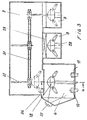
- FIG. 3 shows schematically in section the installation, according to the invention.
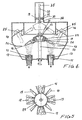
- Figure 4 shows in section on a larger scale the technological room.
- Figure 5 is a sectional view along the line 5-5 of Figure 4.
- FIG. 3 The installation of FIG. 3 comprises four vacuum chambers connected together, a technological master chamber 6, a passage chamber 7 and two chambers 8 and 9.
- the technological chamber comprises crucibles 10 and 11 cooled by a circulation of water and in which are agitated cast materials 12 and 13 to be used for producing the protective coating.
- the number of crucibles may vary depending on the chemical composition of the material.
- a support assembly comprising an axis 21 on which is locked a conical pinion 19 and rotated by means not shown.
- the axis 21 is guided in a sleeve 20.
- the conical pinion 19 cooperates with a series of bevel gears 23 held by a pinion 22 rotating idly on the axis 21.
- Each conical pinion 23 is provided with means for fixing a part to be coated with a ring 24 for protecting the pins. gables 23.
- Electron beam guns 14 open into the chamber 6 and are directed to the crucibles 10 and 11.
- the guns are intended to vaporize the materials of the crucibles 10 and 11;
- the screens 26 open according to a given program, using an automated system.
- the installation may comprise a series of crucibles 16, 17; the percentage of material vaporized and intended to coat the part is greater in the vicinity of the vertical axis of the crucibles and decreases when said part moves away from said axis.
- Vertical screens can be provided extending to the vicinity of the parts to be coated in order to produce coatings which facilitates the production of microlayer coatings, without transition interface and concentration between the layers.
- a manipulator 27 hooks the support 18 and raises it to bring it into the passage chamber 7, then moves it to accommodate it in the chamber 8 on a support member 28 so that the coated parts are cooled.
- a second support 18 furnished with new parts to be coated.
- the chamber 8 is closed by a door 29 and the cooling is accelerated by sending air into the chamber 8.
- the manipulator 27 takes the support of the chamber 9 and brings it into the chamber 6 for a new coating process and so on.
- the manipulator 27 comprises a carriage 30 movable on rails 31 and housed in the chamber 7.
- the carriage is provided with means 32 cooperating with a rod 33 provided with a clamp 34 intended to cooperate with the attachment member 39 of the support 18.
- the clamp 34 can be controlled by an electromagnet 35.
- the carriage 30 comprises electromechanical means for controlling the vertical sliding of the rod 33 as well as its displacement on the rails 31.
- a movable screen 36 which can be erased for the establishment of the support 18 in the chamber 6 and then replaced to separate the chamber 6 of the chamber 7 and thus the arrival of the condensate in the chamber 7 during the process coating.
- the installation comprises a stroboscopic verification system 37 of the coating process arranged on a door of the chamber 6.
- the installation according to the invention is simpler than known installations and makes it possible to deposit coatings of all types.
- the process of deposition of the microlayer coating is different from that described in Example 4, because it is performed by alternating engagement with the determined intervals of the electron beam guns which vaporize the cast products of Cr, Si and Mo respectively.
- Coatings can be formed with the alternation of chromium silicide / molybdenum silicide layers having specified thicknesses and chemical compositions, depending on the time interval and rate of vaporization of the components.
Landscapes
- Chemical & Material Sciences (AREA)
- Chemical Kinetics & Catalysis (AREA)
- Engineering & Computer Science (AREA)
- Materials Engineering (AREA)
- Mechanical Engineering (AREA)
- Metallurgy (AREA)
- Organic Chemistry (AREA)
- Physical Vapour Deposition (AREA)
- Application Of Or Painting With Fluid Materials (AREA)
- Chemical Or Physical Treatment Of Fibers (AREA)
- Spray Control Apparatus (AREA)
Claims (4)
- Anlage zum Elektronenstrahlbeschichten von Werkstücken, die von derjenigen Art ist, die eine Kammer (6) mit Mitteln, um sie unter Vakuum zu halten, Tiegel (10, 11), die dazu vorgesehen sind, zu verdampfende Materialien aufzunehmen, Elektronenstrahlkanonen (25, 14), die dazu vorgesehen sind, die Verdampfung der Materialien zu bewirken, und einen Träger (18) für die zu beschichtenden Werkstücke (15) umfasst, dadurch gekennzeichnet, dass der Träger (18) auf einer vertikalen Achse (22) angebracht ist, die mit Mitteln, um sie in Drehung zu versetzen, verbunden ist und ein auf ihr befestigtes Kegelrad (24) umfasst, das eine Reihe von Kegelrädern (23) antreibt, die mit Mitteln verbunden sind, um zu beschichtende Werkstücke (15) derart zu fixieren, dass Letztere mit ihrem freien Ende auf die Tiegel gerichtet sind.
- Anlage zum Elektronenstrahlbeschichten von Werkstücken nach Anspruch 1, dadurch gekennzeichnet, dass sie Klappen (26) umfasst, um die zu beschichtenden Werkstücke (15) während einer Vorheizung der genannten, zu beschichtenden Werkstücke zu isolieren.
- Anlage zum Elektronenstrahlbeschichten von Werkstücken nach Anspruch 1, dadurch gekennzeichnet, dass der Träger (18) der zu beschichtenden Werkstücke auf der vertikalen Achse (22) unbeweglich angeordnet ist.
- Anlage zum Elektronenstrahlbeschichten von Werkstücken nach den Ansprüchen 1 und 3, dadurch gekennzeichnet, dass sie eine erste Kammer (9), die zur Aufnahme eines Trägers (18) vorgesehen ist, der mit zu beschichtenden Werkstücken (15) versehen ist, Mittel (27), um in der genannten ersten Kammer Vakuum zu erzeugen, eine Durchgangskammer (7), die unter Vakuum gehalten ist und einen Manipulator (27) aufweist, um den in der ersten Kammer befindlichen Träger anzuheben und ihn in die Kammer (6) zu bewegen, in der die zu beschichtenden Werkstücke beschichtet werden müssen, sowie eine dritte Kühlkammer (8) umfasst, die dazu vorgesehen ist, den Träger mit beschichteten Werkstücken (15) aufzunehmen.
Applications Claiming Priority (2)
| Application Number | Priority Date | Filing Date | Title |
|---|---|---|---|
| CH16232003 | 2003-09-23 | ||
| CH16232003 | 2003-09-23 |
Publications (2)
| Publication Number | Publication Date |
|---|---|
| EP1520914A1 EP1520914A1 (de) | 2005-04-06 |
| EP1520914B1 true EP1520914B1 (de) | 2006-05-31 |
Family
ID=34280717
Family Applications (1)
| Application Number | Title | Priority Date | Filing Date |
|---|---|---|---|
| EP03293346A Expired - Lifetime EP1520914B1 (de) | 2003-09-23 | 2003-12-29 | Anlage zum Beschichten von Werkstücken durch Elektronenstrahlen |
Country Status (7)
| Country | Link |
|---|---|
| US (1) | US6923868B2 (de) |
| EP (1) | EP1520914B1 (de) |
| CN (1) | CN1600894A (de) |
| AT (1) | ATE328135T1 (de) |
| CA (1) | CA2451682C (de) |
| DE (1) | DE60305704T2 (de) |
| RU (1) | RU2265078C1 (de) |
Families Citing this family (19)
| Publication number | Priority date | Publication date | Assignee | Title |
|---|---|---|---|---|
| RU2376399C1 (ru) * | 2005-12-05 | 2009-12-20 | Улвак, Инк. | Вакуумный затвор для вакуумного устройства |
| RU2308538C1 (ru) * | 2006-06-19 | 2007-10-20 | Общество с ограниченной ответственностью научно-производственная фирма "ЭЛАН-ПРАКТИК" | Установка для нанесения многослойных покрытий с периодической структурой методом магнетронного распыления |
| EP1947210A1 (de) * | 2007-01-16 | 2008-07-23 | ARCELOR France | Verfahren zur Beschichtung eines Substrats, Anlage zur Umsetzung des Verfahrens und Vorrichtung zur Metallzuführung zu einer solchen Anlage |
| US7997227B2 (en) * | 2007-03-13 | 2011-08-16 | General Electric Company | Vacuum coater device and mechanism for supporting and manipulating workpieces in same |
| RU2391443C2 (ru) * | 2008-06-17 | 2010-06-10 | Лев Викторович Мисожников | Установка для нанесения покрытий в вакууме |
| CN101619446A (zh) | 2008-06-30 | 2010-01-06 | 鸿富锦精密工业(深圳)有限公司 | 镀膜蒸发载具及使用该镀膜蒸发载具的真空镀膜装置 |
| RU2404285C1 (ru) * | 2009-10-22 | 2010-11-20 | Закрытое акционерное общество "Специальное Конструкторско-Технологическое Бюро КАСКАД" (ЗАО "СКТБ КАСКАД") | Установка для нанесения покрытий в вакууме |
| CN102108486B (zh) * | 2009-12-28 | 2014-04-23 | 鸿富锦精密工业(深圳)有限公司 | 镀膜机 |
| RU2437964C2 (ru) * | 2010-01-11 | 2011-12-27 | Вера Дмитриевна Мирошникова | Подложкодержатель и установка для нанесения покрытий методом магнетронного распыления на его основе |
| DE102010017895A1 (de) * | 2010-04-21 | 2011-10-27 | Ald Vacuum Technologies Gmbh | Vorrichtung zum Beschichten von Substraten nach dem EB/PVD-Verfahren |
| SG10201601693VA (en) * | 2011-03-17 | 2016-04-28 | Sulzer Metco Ag | Component manipulator for the dynamic positioning of a substrate, coating method, as well as use of a component manipulator |
| RU2543023C2 (ru) * | 2012-10-01 | 2015-02-27 | Федеральное государственное бюджетное образовательное учреждение высшего профессионального образования "Владимирский государственный университет имени Александра Григорьевича и Николая Григорьевича Столетовых" (ВлГУ) | Роторный подложкодержатель |
| CN104511390A (zh) * | 2013-10-04 | 2015-04-15 | 宁夏中远天晟科技有限公司 | 一种铁路车钩配件的油漆喷涂设备 |
| KR101642188B1 (ko) * | 2014-08-19 | 2016-07-22 | 재단법인 하이브리드 인터페이스기반 미래소재 연구단 | 구조물의 균일 증착을 위하여 비틀림각을 연출하는 지그시스템 |
| RU172351U1 (ru) * | 2017-04-17 | 2017-07-05 | Федеральное государственное бюджетное образовательное учреждение высшего образования "Томский государственный университет систем управления и радиоэлектроники" | Устройство для электронно-лучевого осаждения оксидных покрытий |
| CN107130213B (zh) * | 2017-05-03 | 2019-04-09 | 成都真锐科技涂层技术有限公司 | 多元合金复合薄膜制备设备和制备方法 |
| RU2669953C1 (ru) * | 2017-08-29 | 2018-10-17 | Публичное акционерное общество "Региональный инжиниринговый центр промышленных лазерных технологий "КАИ - Лазер" | Устройство для гибридного лазерно-акустического создания функционально-градиентного материала |
| RU2680115C1 (ru) * | 2017-11-13 | 2019-02-15 | Публичное акционерное общество "Уфимское моторостроительное производственное объединение" (ПАО "ОДК-УМПО") | Способ нанесения покрытия на лопатки газотурбинного двигателя |
| CN121344511B (zh) * | 2025-12-19 | 2026-03-03 | 北矿新材科技有限公司 | 一种高抗热震拱形陶瓷涂层零件及其制备方法和航空发动机 |
Family Cites Families (12)
| Publication number | Priority date | Publication date | Assignee | Title |
|---|---|---|---|---|
| US3656454A (en) * | 1970-11-23 | 1972-04-18 | Air Reduction | Vacuum coating apparatus |
| US3812486A (en) | 1972-04-18 | 1974-05-21 | Antolelic Ind Ltd | Display having a photoconductor gas discharge control |
| FR2183603B1 (de) | 1972-05-12 | 1974-08-30 | Cit Alcatel | |
| CH580990A5 (de) * | 1974-03-04 | 1976-10-29 | Ebauches Sa | |
| JPS5247530A (en) * | 1975-10-14 | 1977-04-15 | Pioneer Electronic Corp | Vaporisation apparatus |
| US4108107A (en) * | 1976-04-01 | 1978-08-22 | Airco, Inc. | Rotatable substrate holder for use in vacuum |
| DE2813180C2 (de) | 1978-03-25 | 1985-12-19 | Leybold-Heraeus GmbH, 5000 Köln | Vakuumbeschichtungsanlage zum allseitigen Beschichten von Substraten durch Rotation der Substrate im Materialstrom |
| FR2644180B1 (fr) * | 1989-03-08 | 1991-05-10 | Commissariat Energie Atomique | Dispositif pour recouvrir une surface plane d'une couche d'epaisseur uniforme |
| RU2038417C1 (ru) * | 1992-06-22 | 1995-06-27 | Бурков Сергей Геннадьевич | Устройство для нанесения покрытий на изделия в вакууме |
| US6083322A (en) * | 1997-03-06 | 2000-07-04 | United Technologies Corporation | Modular coating fixture |
| FR2827307B1 (fr) * | 2001-07-12 | 2004-07-16 | Snecma Moteurs | Procede de reparation locale de pieces revetues d'une barriere thermique en ceramique |
| US7754016B2 (en) * | 2002-10-07 | 2010-07-13 | United Technologies Corporation | Multiple axis tumbler coating apparatus |
-
2003
- 2003-12-23 US US10/744,396 patent/US6923868B2/en not_active Expired - Fee Related
- 2003-12-29 AT AT03293346T patent/ATE328135T1/de not_active IP Right Cessation
- 2003-12-29 DE DE60305704T patent/DE60305704T2/de not_active Expired - Fee Related
- 2003-12-29 EP EP03293346A patent/EP1520914B1/de not_active Expired - Lifetime
- 2003-12-31 CA CA002451682A patent/CA2451682C/fr not_active Expired - Fee Related
-
2004
- 2004-04-27 RU RU2004112868/02A patent/RU2265078C1/ru not_active IP Right Cessation
- 2004-08-24 CN CNA200410064200XA patent/CN1600894A/zh active Pending
Also Published As
| Publication number | Publication date |
|---|---|
| EP1520914A1 (de) | 2005-04-06 |
| CA2451682C (fr) | 2007-03-20 |
| CN1600894A (zh) | 2005-03-30 |
| DE60305704D1 (de) | 2006-07-06 |
| DE60305704T2 (de) | 2007-03-29 |
| RU2004112868A (ru) | 2005-10-27 |
| ATE328135T1 (de) | 2006-06-15 |
| RU2265078C1 (ru) | 2005-11-27 |
| CA2451682A1 (fr) | 2005-03-23 |
| US6923868B2 (en) | 2005-08-02 |
| US20050061250A1 (en) | 2005-03-24 |
Similar Documents
| Publication | Publication Date | Title |
|---|---|---|
| EP1520914B1 (de) | Anlage zum Beschichten von Werkstücken durch Elektronenstrahlen | |
| RU2456372C2 (ru) | Способ нанесения покрытия на подложку и устройство вакуумного осаждения металлического сплава | |
| US6054184A (en) | Method for forming a multilayer thermal barrier coating | |
| Movchan et al. | Graded thermal barrier coatings, deposited by EB-PVD | |
| US6299971B1 (en) | Ceramic coatings containing layered porosity | |
| Von Niessen et al. | Vapor phase deposition using plasma spray-PVD™ | |
| JP4111555B2 (ja) | 中間相のボンドコート付きサーマルバリアコーティングを形成した物品及びこの物品にサーマルバリアコーティングを形成する方法 | |
| EP1111085B1 (de) | Verfahren zur Herstellung von Beschichtungen aus Keramik | |
| EP2506980B1 (de) | Beschichtungsverfahren und -vorrichtung | |
| US20030180571A1 (en) | Microstructured coatings and materials | |
| EP0969117A2 (de) | Verfahren zum Herstellen eines Wärmedämmschichtsystems | |
| JP2007217795A (ja) | 層構造体製造用の部品、装置及び製造方法 | |
| Badini et al. | Cyclic oxidation in burner rig of TiAlN coating deposited on Ti-48Al-2Cr-2Nb by reactive HiPIMS | |
| KR100626777B1 (ko) | 초합금 제품과 그 위에 코팅을 형성하는 장치 및 방법 | |
| US20020081447A1 (en) | Composite ingot for producing by evaporation a functionally graded coating with an outer ceramic layer on a metal substrate and method thereof | |
| EP1504137A1 (de) | Verfahren zur herstellung von nanolaminierten wärmedämmschichten | |
| US3554739A (en) | Alloys and processes for their manufacture | |
| EP1584704A1 (de) | Verfahren zum Schutz von Gegenständen und entsprechende Zusammensetzungen | |
| US6145470A (en) | Apparatus for electron beam physical vapor deposition | |
| EP0845051B1 (de) | Verfahren zur herstellung von konstruktionswerkstoffe durch pvd | |
| US20250257440A1 (en) | Coating comprising a rare earth monosilicate and a rare earth disilicate and method of manufacture thereof | |
| Yumoto et al. | In situ synthesis of titanium-aluminides in coating with supersonic free-jet PVD using Ti and Al nanoparticles | |
| EP1391533A1 (de) | Verfahren zum Schutz von Artikeln, und entsprechende Zusammensetzungen | |
| EP1445344B1 (de) | PVD-Vorrichtung und Verfahren | |
| Yu et al. | Vapor deposition of platinum alloyed nickel aluminide coatings |
Legal Events
| Date | Code | Title | Description |
|---|---|---|---|
| PUAI | Public reference made under article 153(3) epc to a published international application that has entered the european phase |
Free format text: ORIGINAL CODE: 0009012 |
|
| AK | Designated contracting states |
Kind code of ref document: A1 Designated state(s): AT BE BG CH CY CZ DE DK EE ES FI FR GB GR HU IE IT LI LU MC NL PT RO SE SI SK TR |
|
| AX | Request for extension of the european patent |
Extension state: AL LT LV MK |
|
| RAP1 | Party data changed (applicant data changed or rights of an application transferred) |
Owner name: GBA S.A. |
|
| 17P | Request for examination filed |
Effective date: 20050801 |
|
| GRAP | Despatch of communication of intention to grant a patent |
Free format text: ORIGINAL CODE: EPIDOSNIGR1 |
|
| AKX | Designation fees paid |
Designated state(s): AT BE BG CH CY CZ DE DK EE ES FI FR GB GR HU IE IT LI LU MC NL PT RO SE SI SK TR |
|
| GRAS | Grant fee paid |
Free format text: ORIGINAL CODE: EPIDOSNIGR3 |
|
| GRAA | (expected) grant |
Free format text: ORIGINAL CODE: 0009210 |
|
| AK | Designated contracting states |
Kind code of ref document: B1 Designated state(s): AT BE BG CH CY CZ DE DK EE ES FI FR GB GR HU IE IT LI LU MC NL PT RO SE SI SK TR |
|
| PG25 | Lapsed in a contracting state [announced via postgrant information from national office to epo] |
Ref country code: IE Free format text: LAPSE BECAUSE OF FAILURE TO SUBMIT A TRANSLATION OF THE DESCRIPTION OR TO PAY THE FEE WITHIN THE PRESCRIBED TIME-LIMIT Effective date: 20060531 Ref country code: IT Free format text: LAPSE BECAUSE OF FAILURE TO SUBMIT A TRANSLATION OF THE DESCRIPTION OR TO PAY THE FEE WITHIN THE PRESCRIBED TIME-LIMIT;WARNING: LAPSES OF ITALIAN PATENTS WITH EFFECTIVE DATE BEFORE 2007 MAY HAVE OCCURRED AT ANY TIME BEFORE 2007. THE CORRECT EFFECTIVE DATE MAY BE DIFFERENT FROM THE ONE RECORDED. Effective date: 20060531 Ref country code: SI Free format text: LAPSE BECAUSE OF FAILURE TO SUBMIT A TRANSLATION OF THE DESCRIPTION OR TO PAY THE FEE WITHIN THE PRESCRIBED TIME-LIMIT Effective date: 20060531 Ref country code: NL Free format text: LAPSE BECAUSE OF FAILURE TO SUBMIT A TRANSLATION OF THE DESCRIPTION OR TO PAY THE FEE WITHIN THE PRESCRIBED TIME-LIMIT Effective date: 20060531 Ref country code: SK Free format text: LAPSE BECAUSE OF FAILURE TO SUBMIT A TRANSLATION OF THE DESCRIPTION OR TO PAY THE FEE WITHIN THE PRESCRIBED TIME-LIMIT Effective date: 20060531 Ref country code: FI Free format text: LAPSE BECAUSE OF FAILURE TO SUBMIT A TRANSLATION OF THE DESCRIPTION OR TO PAY THE FEE WITHIN THE PRESCRIBED TIME-LIMIT Effective date: 20060531 Ref country code: CZ Free format text: LAPSE BECAUSE OF FAILURE TO SUBMIT A TRANSLATION OF THE DESCRIPTION OR TO PAY THE FEE WITHIN THE PRESCRIBED TIME-LIMIT Effective date: 20060531 |
|
| REG | Reference to a national code |
Ref country code: CH Ref legal event code: EP Ref country code: GB Ref legal event code: FG4D Free format text: NOT ENGLISH |
|
| REG | Reference to a national code |
Ref country code: IE Ref legal event code: FG4D Free format text: LANGUAGE OF EP DOCUMENT: FRENCH |
|
| REF | Corresponds to: |
Ref document number: 60305704 Country of ref document: DE Date of ref document: 20060706 Kind code of ref document: P |
|
| REG | Reference to a national code |
Ref country code: RO Ref legal event code: EPE |
|
| PG25 | Lapsed in a contracting state [announced via postgrant information from national office to epo] |
Ref country code: DK Free format text: LAPSE BECAUSE OF FAILURE TO SUBMIT A TRANSLATION OF THE DESCRIPTION OR TO PAY THE FEE WITHIN THE PRESCRIBED TIME-LIMIT Effective date: 20060831 Ref country code: SE Free format text: LAPSE BECAUSE OF FAILURE TO SUBMIT A TRANSLATION OF THE DESCRIPTION OR TO PAY THE FEE WITHIN THE PRESCRIBED TIME-LIMIT Effective date: 20060831 |
|
| PG25 | Lapsed in a contracting state [announced via postgrant information from national office to epo] |
Ref country code: ES Free format text: LAPSE BECAUSE OF FAILURE TO SUBMIT A TRANSLATION OF THE DESCRIPTION OR TO PAY THE FEE WITHIN THE PRESCRIBED TIME-LIMIT Effective date: 20060911 |
|
| GBT | Gb: translation of ep patent filed (gb section 77(6)(a)/1977) |
Effective date: 20060911 |
|
| PGFP | Annual fee paid to national office [announced via postgrant information from national office to epo] |
Ref country code: FR Payment date: 20061027 Year of fee payment: 4 |
|
| PG25 | Lapsed in a contracting state [announced via postgrant information from national office to epo] |
Ref country code: PT Free format text: LAPSE BECAUSE OF FAILURE TO SUBMIT A TRANSLATION OF THE DESCRIPTION OR TO PAY THE FEE WITHIN THE PRESCRIBED TIME-LIMIT Effective date: 20061031 |
|
| NLV1 | Nl: lapsed or annulled due to failure to fulfill the requirements of art. 29p and 29m of the patents act | ||
| PGFP | Annual fee paid to national office [announced via postgrant information from national office to epo] |
Ref country code: AT Payment date: 20061117 Year of fee payment: 4 |
|
| PGFP | Annual fee paid to national office [announced via postgrant information from national office to epo] |
Ref country code: RO Payment date: 20061130 Year of fee payment: 4 |
|
| PGFP | Annual fee paid to national office [announced via postgrant information from national office to epo] |
Ref country code: DE Payment date: 20061211 Year of fee payment: 4 |
|
| PG25 | Lapsed in a contracting state [announced via postgrant information from national office to epo] |
Ref country code: BE Free format text: LAPSE BECAUSE OF NON-PAYMENT OF DUE FEES Effective date: 20061231 Ref country code: MC Free format text: LAPSE BECAUSE OF NON-PAYMENT OF DUE FEES Effective date: 20061231 |
|
| REG | Reference to a national code |
Ref country code: IE Ref legal event code: FD4D |
|
| PLBE | No opposition filed within time limit |
Free format text: ORIGINAL CODE: 0009261 |
|
| STAA | Information on the status of an ep patent application or granted ep patent |
Free format text: STATUS: NO OPPOSITION FILED WITHIN TIME LIMIT |
|
| 26N | No opposition filed |
Effective date: 20070301 |
|
| BERE | Be: lapsed |
Owner name: GBA S.A. Effective date: 20061231 |
|
| PG25 | Lapsed in a contracting state [announced via postgrant information from national office to epo] |
Ref country code: GR Free format text: LAPSE BECAUSE OF FAILURE TO SUBMIT A TRANSLATION OF THE DESCRIPTION OR TO PAY THE FEE WITHIN THE PRESCRIBED TIME-LIMIT Effective date: 20060901 |
|
| PG25 | Lapsed in a contracting state [announced via postgrant information from national office to epo] |
Ref country code: BG Free format text: LAPSE BECAUSE OF FAILURE TO SUBMIT A TRANSLATION OF THE DESCRIPTION OR TO PAY THE FEE WITHIN THE PRESCRIBED TIME-LIMIT Effective date: 20060831 Ref country code: EE Free format text: LAPSE BECAUSE OF FAILURE TO SUBMIT A TRANSLATION OF THE DESCRIPTION OR TO PAY THE FEE WITHIN THE PRESCRIBED TIME-LIMIT Effective date: 20060531 |
|
| PG25 | Lapsed in a contracting state [announced via postgrant information from national office to epo] |
Ref country code: HU Free format text: LAPSE BECAUSE OF FAILURE TO SUBMIT A TRANSLATION OF THE DESCRIPTION OR TO PAY THE FEE WITHIN THE PRESCRIBED TIME-LIMIT Effective date: 20061201 Ref country code: TR Free format text: LAPSE BECAUSE OF FAILURE TO SUBMIT A TRANSLATION OF THE DESCRIPTION OR TO PAY THE FEE WITHIN THE PRESCRIBED TIME-LIMIT Effective date: 20060531 Ref country code: LU Free format text: LAPSE BECAUSE OF NON-PAYMENT OF DUE FEES Effective date: 20061229 |
|
| GBPC | Gb: european patent ceased through non-payment of renewal fee |
Effective date: 20071229 |
|
| PG25 | Lapsed in a contracting state [announced via postgrant information from national office to epo] |
Ref country code: AT Free format text: LAPSE BECAUSE OF NON-PAYMENT OF DUE FEES Effective date: 20071229 |
|
| PG25 | Lapsed in a contracting state [announced via postgrant information from national office to epo] |
Ref country code: DE Free format text: LAPSE BECAUSE OF NON-PAYMENT OF DUE FEES Effective date: 20080701 |
|
| REG | Reference to a national code |
Ref country code: FR Ref legal event code: ST Effective date: 20081020 |
|
| PG25 | Lapsed in a contracting state [announced via postgrant information from national office to epo] |
Ref country code: RO Free format text: LAPSE BECAUSE OF NON-PAYMENT OF DUE FEES Effective date: 20071229 Ref country code: CY Free format text: LAPSE BECAUSE OF FAILURE TO SUBMIT A TRANSLATION OF THE DESCRIPTION OR TO PAY THE FEE WITHIN THE PRESCRIBED TIME-LIMIT Effective date: 20060531 |
|
| PG25 | Lapsed in a contracting state [announced via postgrant information from national office to epo] |
Ref country code: GB Free format text: LAPSE BECAUSE OF NON-PAYMENT OF DUE FEES Effective date: 20071229 |
|
| PGFP | Annual fee paid to national office [announced via postgrant information from national office to epo] |
Ref country code: CH Payment date: 20081106 Year of fee payment: 6 |
|
| PG25 | Lapsed in a contracting state [announced via postgrant information from national office to epo] |
Ref country code: FR Free format text: LAPSE BECAUSE OF NON-PAYMENT OF DUE FEES Effective date: 20071231 |
|
| REG | Reference to a national code |
Ref country code: CH Ref legal event code: PL |
|
| PG25 | Lapsed in a contracting state [announced via postgrant information from national office to epo] |
Ref country code: LI Free format text: LAPSE BECAUSE OF NON-PAYMENT OF DUE FEES Effective date: 20091231 Ref country code: CH Free format text: LAPSE BECAUSE OF NON-PAYMENT OF DUE FEES Effective date: 20091231 |