EP1521052A1 - Munition perforante - Google Patents
Munition perforante Download PDFInfo
- Publication number
- EP1521052A1 EP1521052A1 EP04292218A EP04292218A EP1521052A1 EP 1521052 A1 EP1521052 A1 EP 1521052A1 EP 04292218 A EP04292218 A EP 04292218A EP 04292218 A EP04292218 A EP 04292218A EP 1521052 A1 EP1521052 A1 EP 1521052A1
- Authority
- EP
- European Patent Office
- Prior art keywords
- ammunition according
- bars
- insert
- penetration
- piercing
- Prior art date
- Legal status (The legal status is an assumption and is not a legal conclusion. Google has not performed a legal analysis and makes no representation as to the accuracy of the status listed.)
- Granted
Links
- 230000035515 penetration Effects 0.000 claims abstract description 31
- 239000000463 material Substances 0.000 claims abstract description 20
- 239000002360 explosive Substances 0.000 claims description 8
- 239000003380 propellant Substances 0.000 claims description 6
- 229910045601 alloy Inorganic materials 0.000 claims description 5
- 239000000956 alloy Substances 0.000 claims description 5
- 239000000843 powder Substances 0.000 claims description 4
- 238000004080 punching Methods 0.000 claims 3
- 229910000831 Steel Inorganic materials 0.000 description 6
- 239000010959 steel Substances 0.000 description 6
- 238000004519 manufacturing process Methods 0.000 description 5
- 229910001080 W alloy Inorganic materials 0.000 description 4
- 238000005245 sintering Methods 0.000 description 3
- 238000001514 detection method Methods 0.000 description 2
- 230000003116 impacting effect Effects 0.000 description 2
- 238000000034 method Methods 0.000 description 2
- 230000000284 resting effect Effects 0.000 description 2
- 229910052715 tantalum Inorganic materials 0.000 description 2
- GUVRBAGPIYLISA-UHFFFAOYSA-N tantalum atom Chemical compound [Ta] GUVRBAGPIYLISA-UHFFFAOYSA-N 0.000 description 2
- WFKWXMTUELFFGS-UHFFFAOYSA-N tungsten Chemical compound [W] WFKWXMTUELFFGS-UHFFFAOYSA-N 0.000 description 2
- 229910052721 tungsten Inorganic materials 0.000 description 2
- 239000010937 tungsten Substances 0.000 description 2
- JFALSRSLKYAFGM-UHFFFAOYSA-N uranium(0) Chemical compound [U] JFALSRSLKYAFGM-UHFFFAOYSA-N 0.000 description 2
- 235000015842 Hesperis Nutrition 0.000 description 1
- 235000012633 Iberis amara Nutrition 0.000 description 1
- 229910052770 Uranium Inorganic materials 0.000 description 1
- 238000005266 casting Methods 0.000 description 1
- 230000006835 compression Effects 0.000 description 1
- 238000007906 compression Methods 0.000 description 1
- 230000006378 damage Effects 0.000 description 1
- 238000009826 distribution Methods 0.000 description 1
- 238000005553 drilling Methods 0.000 description 1
- 230000000977 initiatory effect Effects 0.000 description 1
- 230000008520 organization Effects 0.000 description 1
- 230000002093 peripheral effect Effects 0.000 description 1
- 239000011819 refractory material Substances 0.000 description 1
- 230000035939 shock Effects 0.000 description 1
- 238000003860 storage Methods 0.000 description 1
- 230000003313 weakening effect Effects 0.000 description 1
Images


Classifications
-
- F—MECHANICAL ENGINEERING; LIGHTING; HEATING; WEAPONS; BLASTING
- F42—AMMUNITION; BLASTING
- F42B—EXPLOSIVE CHARGES, e.g. FOR BLASTING, FIREWORKS, AMMUNITION
- F42B12/00—Projectiles, missiles or mines characterised by the warhead, the intended effect, or the material
- F42B12/02—Projectiles, missiles or mines characterised by the warhead, the intended effect, or the material characterised by the warhead or the intended effect
- F42B12/04—Projectiles, missiles or mines characterised by the warhead, the intended effect, or the material characterised by the warhead or the intended effect of armour-piercing type
- F42B12/06—Projectiles, missiles or mines characterised by the warhead, the intended effect, or the material characterised by the warhead or the intended effect of armour-piercing type with hard or heavy core; Kinetic energy penetrators
Definitions
- the technical field of the invention is that of ammunition allowing the destruction of targets strongly protected by a wall for example of concrete.
- the body piercing this ammunition has an insert massive which is embedded inside the body material.
- This insert is made of a dense and resistant alloy mechanically, chosen for example from among the materials refractories and their alloys (tungsten, tantalum, uranium).
- the material of the body is formed by steel which is poured around the insert.
- This ammunition has the disadvantage of being complex to manufacture. It is difficult and expensive to achieve a dense core of large diameter (greater than 90mm) and having high mechanical characteristics in a way reproducible (density greater than 13, elastic limit greater than 1000 Mega Pascals). Indeed these materials are implemented in the form of powders by the techniques of compression.
- the munition according to the invention to ensure the perforation of a concrete target regardless the angle of impact on the target.
- the invention relates to a perforating munition comprising a penetration body delimiting a cavity internal closed by a base, ammunition characterized in that the penetration body is made of a material having a yield strength greater than or equal to 1,200 Mega Pascals and has a front tip comprising at least one insert integral with the tip, insert made of a material high mechanical characteristics, denser than that of the body and disposed in a housing opening out of the body.
- the inserts are shaped into radially arranged segments around an axial extension of the body, segments rendered integral with the body by a connecting means.
- the connecting means may comprise at least one ring surrounding the inserts.
- This piercing ammunition may also include a dense alloy nose at the end of the extension axial axis of the body and having a rear surface resting on the segments.
- each insert may be constituted by a bar substantially cylindrical housed in a bore body penetration.
- the piercing ammunition can thus comprise an insert single axis with a forward tip extending the body penetration.
- This ammunition may then include a charge of propellant powder for ejecting the insert out of the body penetration.
- the ammunition can have at least one ring of bars regularly arranged around an axis of the penetration body.
- It can thus comprise two crowns of bars regularly arranged around an axis of the body of penetration.
- the ends of the bars can be flush with an outer surface of the penetration body.
- the ends of the bars may instead be protrusion outside the penetration body.
- Each bar may have its axis inclined relative to the axis of the body of penetration.
- the ends of the bars of a crown and another crown and / or axial bar may be substantially in the same plane.
- the internal cavity may contain at least one load explosive.
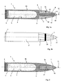
- an ammunition perforant 1 according to one embodiment of the invention comprises a penetration body 2 which delimits a cavity internal 3 closed by a base 4.
- This ammunition could be an air / ground bomb or a missile or a missile military head. She will have a diameter greater than 100 mm and a length of about 1.5m.
- it may have a rear part (not shown) incorporating a thruster that will give it a range or speed given.
- the internal cavity 3 contains an explosive charge 5 which can be initiated by a rocket 6 disposed in the vicinity of the base 4.
- the rocket shall be designed to ensure the detection crossing a wall and then initiating the loading explosive once this wall crossed.
- Such rockets are well known to those skilled in the art. We can for example see US5255608 which describes such a rocket.
- Penetration body 2 has a front tip 2a which is extended by a rear cylindrical portion 2b delimiting the internal cavity 3.
- This body is made of high material mechanical characteristics, ie a material whose elastic limit is greater than or equal to 1200 Mega Pascals.
- 35NCD16 steel may be used.
- the front tip 2a comprises inserts 7 made of a denser material than the one 2.
- These inserts are made of a dense material to high mechanical characteristics.
- the inserts 7 are here shaped into segments arranged radially around an axial axial extension 8 of the body 2.
- each segment is in contact with the body 2, on the one hand at the axial extension 8 and on the other share with a shoulder 9 of the body 2. Free space surrounding the axial extension 8 thus constitutes a dwelling for the inserts.
- Each insert 7 is also in contact with two other neighboring inserts.
- the set of inserts thus forms the ogee-shaped part of the front tip 2a of the penetration body 2.
- the inserts 7 are made integral with the body by a connecting means which comprises at least one ring 10 surrounding the inserts 7. This ring will be made of steel. She is will lodge in a groove 11 formed by the juxtaposition notches carried by each insert.
- the ammunition 1 also has a nose 12 which is it also made of a dense alloy. This nose is set at a end 14 of smaller diameter carried by the extension axial 8 of the body 2.
- the nose 12 has a rear surface 13 resting on the inserts 7.
- the nose 12 is fixed on the end 14 for example by thread. It allows to transmit to different inserts 7 shock when impacting a target.
- the munition according to the invention combines an ogive of large diameter (greater than 90 mm) and capacity important perforator with a steel body function to ensure the carriage of the explosive charge and the maintaining perforating inserts.
- the inserts have reasonable dimensions (section of the order of 2000 mm 2 to 6000 mm 2 ) which allows their manufacture according to sintering techniques already implemented for artillery arrows projectiles.
- the design of the munition according to the invention it also becomes possible to improve a munition in replacing at the end of a storage phase the inserts 7 initially provided by inserts with improved mechanical characteristics.
- FIG. 2 shows a munition 1 according to another mode of embodiment of the invention.
- This mode differs from the previous one only in the structure of the front tip 2a.
- the nose 2a here comprises an axial bore 15 to inside which is positioned an insert 7 having the shape of a substantially cylindrical bar and made of a denser material than the body 2.
- the front tip 16 of this insert has an ogee shape which extends the body of penetration 2.
- This insert 7 will thus have a diameter of the order of 30 to 40 mm for a penetration body 2 of diameter 90 mm. Her manufacturing is thus facilitated.
- the implementation of a tungsten alloy with high mechanical properties allows to confer on this point a perforating character and no simple ballast. This improves the capacity of perforation of the ammunition for a given mass.
- the ammunition shown in Figure 3 also includes a single insert 7 of dense material disposed in a bore axial 15.
- This insert 7 has an internal cavity 17 inside of which is disposed a charge of propellant powder 18.
- a device 19 for igniting this charge is housed in the body 2. It is connected by a link wired 20 to the rocket 6.
- the latter will then include a chronometric module or a proximity detection module (connected to a antenna not shown integral with the body's warhead 2) which will trigger the ignition of the propellant charge 18 before the impact on a target and at a distance from it the order of 3 to 4 calibers.
- a chronometric module or a proximity detection module connected to a antenna not shown integral with the body's warhead 2 which will trigger the ignition of the propellant charge 18 before the impact on a target and at a distance from it the order of 3 to 4 calibers.
- the propellant charge 18 will ensure the ejection of the insert 7 out of the body of penetration 2. It will thus be propelled towards the target.
- the speed differential between insert 7 and the body 2 will be of the order of 200 m / s. Such a provision allows to increase the perforation capabilities of the ammunition without increasing its speed.
- the insert will ensure the drilling of a pre-hole in the target, the penetration body will then impact the target at level of this before hole.
- Figures 4a, 4b and 4c show another mode of production of a perforating munition according to the invention.
- This mode differs from the previous ones only in the structure of the piercing head 2a which here comprises several bars 7a, 7b, 7c crimped into bores arranged in the body of the tip 2a.
- Each bar 7a, 7b, 7c is cylindrical and the axis of its bore is parallel to the axis 21 of the piercing head 2a.
- the bars 7a and 7b are thus distributed in two concentric rings surrounding the axis 21 of the head perforating.
- a bar 7c also occupies a bore coaxial to the head 2a (see also Figure 4c).
- first crown or middle crown comprising eight bars 7b regularly distributed around axis 21 and a second crown or outer ring comprising sixteen bars 7a regularly distributed around axis 21.
- the diameters of the peripheral bars 7a are here lower than those of the median bars 7b.
- the diameters of different bars may be identical or different for reasons of organization of the piercing head. The goal sought is to obtain the highest overall density for the piercing head.
- the diameters of the bars can be between 10 mm and 30 mm.
- the bars are still made of a dense material, for example, a tungsten alloy obtained by sintering. Because of the reduced diameter for the bars, we can here adopt a material with mechanical characteristics such as a tungsten alloy whose elastic limit will be greater than or equal to 1500 Mega Pascals.
- the body of the heads 2a is made of steel.
- This embodiment makes it easy to obtain a front tip 2a having a high density. It is indeed more easy to make dense bars of reduced diameter (from order of 10 to 30 mm) than to achieve a peak before large diameter (greater than 150mm) in such a sintered material.
- FIGS 5a and 5b represent another mode of which differs from the preceding only in the form of bars 7.
- each bar 7a and 7b protrude outside the body of 2.
- Each bar therefore has a point 22 which extends outside the outer surface of the spike before 2a.
- the axes of the bars 7a, 7b and 7c are again all parallel to the axis 21 of the ammunition.
- Figures 6a and 6b show another way of analogous to that of Figures 5a and 5b but in which each bar 7a or 7b has its axis 23a or 23b inclined with respect to the axis 21 of the penetration body 2.
- the bars 7a of the outer ring have an axis 23a which is inclined at an angle ⁇ of the order of 20 ° to 30 °.
- the bars 7b of the middle crown have an axis 23b which is inclined by an angle ⁇ of the order of 10 ° to 15 °.
- This provision also makes it possible the attachment of the nose 2a on the target during a impact with impact.
- this embodiment makes it possible to to increase the rigging capacity without increasing the masses or diameters of bars 7.
- Figure 7a shows another embodiment similar to that of Figures 5a and 5b but in which the bars 7b of the middle crown have a length such that their tip 22 is substantially at the level of the tip 22 of the axial bar 7c (so at the same plane 24).
- Such an embodiment makes it possible to ensure simultaneous weakening of the target at the level of several point of impact. This improves the perforation.
- Figure 7b shows an embodiment similar to that of Figure 7a but in which all the bars have a length such that their tip 22 is substantially at the point 22 of the axial bar 7c (therefore at the level from the same plane 24).
- the explosive charge 5 by a different kind of loading, for example a incendiary charge or one or more submunitions explosive and / or incendiary ejected after perforation of target.
Landscapes
- Engineering & Computer Science (AREA)
- Chemical & Material Sciences (AREA)
- Combustion & Propulsion (AREA)
- General Engineering & Computer Science (AREA)
- Portable Nailing Machines And Staplers (AREA)
- Aiming, Guidance, Guns With A Light Source, Armor, Camouflage, And Targets (AREA)
- Supply Devices, Intensifiers, Converters, And Telemotors (AREA)
- Powder Metallurgy (AREA)
- Transition And Organic Metals Composition Catalysts For Addition Polymerization (AREA)
- Medicines Containing Material From Animals Or Micro-Organisms (AREA)
- Preliminary Treatment Of Fibers (AREA)
Abstract
Description
- les figures 1a et 1b montrent un premier mode de réalisation d'une munition selon l'invention, la figure 1a étant une coupe longitudinale et la figure 1b une vue externe non coupée de cette munition,
- la figure 2 montre un deuxième mode de réalisation d'une munition selon l'invention,
- la figure 3 montre un troisième mode de réalisation d'une munition selon l'invention,
- les figures 4a, 4b et 4c montrent un quatrième mode de réalisation d'une munition selon l'invention, la figure 4a étant une coupe longitudinale, la figure 4b une vue externe non coupée de cette munition et la figure 4c étant une vue de face de l'ogive de cette munition,
- les figures 5a et 5b montrent une variante de réalisation de ce quatrième mode de réalisation, la figure 5a étant une coupe longitudinale et la figure 5b une vue externe non coupée de cette munition,
- les figures 6a et 6b montrent une autre variante de réalisation de ce quatrième mode de réalisation, la figure 6a étant une coupe longitudinale et la figure 6b une vue externe non coupée de cette munition.
- les figures 7a et 7b montrent en coupe longitudinale deux autres variantes de réalisation de la munition selon l'invention.
Claims (14)
- Munition perforante (1) comprenant un corps de pénétration (2) délimitant une cavité interne (3) fermée par un culot (4), caractérisée en ce que le corps de pénétration (2) est réalisé en un matériau ayant une limite élastique supérieure ou égale à 1200 Méga Pascals et comporte une pointe avant (2a) comprenant au moins un insert (7,7a,7b,7c) solidaire de la pointe (2a), insert réalisé en un matériau à hautes caractéristiques mécaniques, plus dense que celui du corps et disposé dans un logement débouchant à l'extérieur du corps.
- Munition perforante selon la revendication 1, caractérisée en ce que les inserts (7) sont conformés en segments disposés radialement autour d'un prolongement axial (8) du corps (2), segments rendus solidaires du corps par un moyen de liaison.
- Munition perforante selon la revendication 2, caractérisée en ce que le moyen de liaison comprend au moins une bague (10) entourant les inserts (7).
- Munition perforante selon une des revendications 2 ou 3, caractérisée en ce qu'elle comporte un nez (12) en alliage dense disposé à l'extrémité du prolongement axial (8) du corps et comportant une surface arrière (13) en appui sur les segments (7).
- Munition perforante selon la revendication 1, caractérisée en ce que chaque insert (7) est constitué par un barreau sensiblement cylindrique logé dans un alésage du corps de pénétration (2).
- Munition perforante selon la revendication 5, caractérisée en ce qu'elle comporte un insert axial (7) unique comportant une pointe avant (16) prolongeant le corps de pénétration (2).
- Munition perforante selon la revendication 6, caractérisée en ce qu'elle comporte une charge de poudre propulsive (18) permettant d'éjecter l'insert (7) hors du corps de pénétration (2).
- Munition perforante selon la revendication 5, caractérisée en ce qu'elle comporte au moins une couronne de barreaux (7a,7b) régulièrement disposés autour d'un axe (21) du corps de pénétration (2).
- Munition perforante selon la revendication 8, caractérisée en ce qu'elle comporte deux couronnes de barreaux (7a,7b) régulièrement disposés autour d'un axe (21) du corps de pénétration (2).
- Munition perforante selon une des revendications 8 ou 9, caractérisée en ce que les extrémités des barreaux (7a,7b) sont affleurantes avec une surface externe du corps de pénétration (2).
- Munition perforante selon une des revendications 8 ou 9, caractérisée en ce que les extrémités des barreaux (7a,7b) sont en saillie à l'extérieur du corps de pénétration (2).
- Munition perforante selon la revendication 11, caractérisée en ce que chaque barreau (7a,7b) a son axe incliné par rapport à l'axe (21) du corps de pénétration (2).
- Munition perforante selon une des revendications 11 ou 12, caractérisée en ce que les extrémités des barreaux (7a,7b) d'une couronne et d'une autre couronne et/ou d'un barreau axial (7c) se trouvent sensiblement dans un même plan (24).
- Munition perforante selon une des revendications 1 à 13, caractérisée en ce que la cavité interne (3) renferme au moins un chargement explosif (5).
Priority Applications (1)
| Application Number | Priority Date | Filing Date | Title |
|---|---|---|---|
| EP06076213A EP1701131B1 (fr) | 2003-10-03 | 2004-09-16 | Munition perforante |
Applications Claiming Priority (2)
| Application Number | Priority Date | Filing Date | Title |
|---|---|---|---|
| FR0311645 | 2003-10-03 | ||
| FR0311645A FR2860579B1 (fr) | 2003-10-03 | 2003-10-03 | Munition perforante |
Related Child Applications (1)
| Application Number | Title | Priority Date | Filing Date |
|---|---|---|---|
| EP06076213A Division EP1701131B1 (fr) | 2003-10-03 | 2004-09-16 | Munition perforante |
Publications (2)
| Publication Number | Publication Date |
|---|---|
| EP1521052A1 true EP1521052A1 (fr) | 2005-04-06 |
| EP1521052B1 EP1521052B1 (fr) | 2007-06-20 |
Family
ID=34307428
Family Applications (2)
| Application Number | Title | Priority Date | Filing Date |
|---|---|---|---|
| EP06076213A Expired - Lifetime EP1701131B1 (fr) | 2003-10-03 | 2004-09-16 | Munition perforante |
| EP04292218A Expired - Lifetime EP1521052B1 (fr) | 2003-10-03 | 2004-09-16 | Munition perforante |
Family Applications Before (1)
| Application Number | Title | Priority Date | Filing Date |
|---|---|---|---|
| EP06076213A Expired - Lifetime EP1701131B1 (fr) | 2003-10-03 | 2004-09-16 | Munition perforante |
Country Status (6)
| Country | Link |
|---|---|
| US (1) | US7063020B2 (fr) |
| EP (2) | EP1701131B1 (fr) |
| AT (1) | ATE365307T1 (fr) |
| DE (2) | DE602004026633D1 (fr) |
| ES (2) | ES2288669T3 (fr) |
| FR (1) | FR2860579B1 (fr) |
Cited By (2)
| Publication number | Priority date | Publication date | Assignee | Title |
|---|---|---|---|---|
| EP2372296A1 (fr) * | 2010-03-30 | 2011-10-05 | Nexter Munitions | Pénétrateur à énergie cinétique |
| EP2636985A1 (fr) | 2012-03-06 | 2013-09-11 | Nexter Munitions | Projectile sous calibre à structure de tête aménagée |
Families Citing this family (6)
| Publication number | Priority date | Publication date | Assignee | Title |
|---|---|---|---|---|
| US7743409B2 (en) * | 2005-07-08 | 2010-06-22 | Sandisk Corporation | Methods used in a mass storage device with automated credentials loading |
| US8985026B2 (en) | 2011-11-22 | 2015-03-24 | Alliant Techsystems Inc. | Penetrator round assembly |
| IL219010A (en) * | 2012-04-03 | 2016-11-30 | Amon Jacob | Warhead |
| US9212876B1 (en) * | 2013-08-30 | 2015-12-15 | The United States Of America As Represented By The Secretary Of The Army | Large caliber frangible projectile |
| US11027859B2 (en) | 2017-10-16 | 2021-06-08 | The Boeing Company | Variable stiffness flyer plate for penetration device |
| DE102020116589A1 (de) | 2020-06-24 | 2021-12-30 | Rheinmetall Waffe Munition Gmbh | Penetrator, Verwendung eines Penetrators und Geschoss |
Citations (8)
| Publication number | Priority date | Publication date | Assignee | Title |
|---|---|---|---|---|
| GB107252A (en) * | 1916-06-27 | 1917-06-27 | William Warburton | Improvements in the Manufacture of Armour Piercing Bursting Shells or Projectiles. |
| US3203349A (en) * | 1962-09-18 | 1965-08-31 | Kohlswa Jernverks Ab | Projectile or the like, preferably for armor-piercing weapons, and a method of manufacturing such a projectile |
| US3731630A (en) * | 1969-08-05 | 1973-05-08 | Oerlikon Buehrle Ag | High-explosive armor-piercing shell |
| US4108072A (en) * | 1964-12-29 | 1978-08-22 | Deutsch-Franzosisches Forschungsinstitut | Armor-piercing projectile having spaced cores |
| WO1987007708A1 (fr) * | 1986-06-09 | 1987-12-17 | Royal Ordnance Pld | Projectile transpersant un blindage |
| DE9018051U1 (de) * | 1990-07-24 | 1994-04-07 | Rheinmetall Gmbh, 40882 Ratingen | Unterkalibriges Wuchtgeschoß |
| FR2771496A1 (fr) * | 1983-10-27 | 1999-05-28 | Rheinmetall Gmbh | Projectile sans allumeur, provoquant au moins la formation d'eclats et un effet d'energie cinetique au moment de l'impact |
| US6186072B1 (en) | 1999-02-22 | 2001-02-13 | Sandia Corporation | Monolithic ballasted penetrator |
Family Cites Families (5)
| Publication number | Priority date | Publication date | Assignee | Title |
|---|---|---|---|---|
| US3464356A (en) * | 1967-12-28 | 1969-09-02 | Us Army | Self-stabilizing rod penetrators |
| US4597333A (en) * | 1983-07-08 | 1986-07-01 | Rheinmetall G.M.B.H. | Two-part armor-piercing projectile |
| US4573412A (en) * | 1984-04-27 | 1986-03-04 | The United States Of America As Represented By The Secretary Of The Army | Plug nozzle kinetic energy penetrator rocket |
| US5255608A (en) | 1992-12-16 | 1993-10-26 | The United States Of America As Represented By The Secretary Of The Air Force | Real-time identification of a medium for a high-speed penetrator |
| DE10332257A1 (de) * | 2003-07-16 | 2005-02-03 | Rheinmetall W & M Gmbh | Gefechtskopf |
-
2003
- 2003-10-03 FR FR0311645A patent/FR2860579B1/fr not_active Expired - Fee Related
-
2004
- 2004-09-16 EP EP06076213A patent/EP1701131B1/fr not_active Expired - Lifetime
- 2004-09-16 DE DE602004026633T patent/DE602004026633D1/de not_active Expired - Lifetime
- 2004-09-16 EP EP04292218A patent/EP1521052B1/fr not_active Expired - Lifetime
- 2004-09-16 AT AT04292218T patent/ATE365307T1/de not_active IP Right Cessation
- 2004-09-16 ES ES04292218T patent/ES2288669T3/es not_active Expired - Lifetime
- 2004-09-16 ES ES06076213T patent/ES2344597T3/es not_active Expired - Lifetime
- 2004-09-16 DE DE602004007080T patent/DE602004007080T2/de not_active Expired - Lifetime
- 2004-09-24 US US10/948,232 patent/US7063020B2/en not_active Expired - Fee Related
Patent Citations (8)
| Publication number | Priority date | Publication date | Assignee | Title |
|---|---|---|---|---|
| GB107252A (en) * | 1916-06-27 | 1917-06-27 | William Warburton | Improvements in the Manufacture of Armour Piercing Bursting Shells or Projectiles. |
| US3203349A (en) * | 1962-09-18 | 1965-08-31 | Kohlswa Jernverks Ab | Projectile or the like, preferably for armor-piercing weapons, and a method of manufacturing such a projectile |
| US4108072A (en) * | 1964-12-29 | 1978-08-22 | Deutsch-Franzosisches Forschungsinstitut | Armor-piercing projectile having spaced cores |
| US3731630A (en) * | 1969-08-05 | 1973-05-08 | Oerlikon Buehrle Ag | High-explosive armor-piercing shell |
| FR2771496A1 (fr) * | 1983-10-27 | 1999-05-28 | Rheinmetall Gmbh | Projectile sans allumeur, provoquant au moins la formation d'eclats et un effet d'energie cinetique au moment de l'impact |
| WO1987007708A1 (fr) * | 1986-06-09 | 1987-12-17 | Royal Ordnance Pld | Projectile transpersant un blindage |
| DE9018051U1 (de) * | 1990-07-24 | 1994-04-07 | Rheinmetall Gmbh, 40882 Ratingen | Unterkalibriges Wuchtgeschoß |
| US6186072B1 (en) | 1999-02-22 | 2001-02-13 | Sandia Corporation | Monolithic ballasted penetrator |
Cited By (4)
| Publication number | Priority date | Publication date | Assignee | Title |
|---|---|---|---|---|
| EP2372296A1 (fr) * | 2010-03-30 | 2011-10-05 | Nexter Munitions | Pénétrateur à énergie cinétique |
| EP2636985A1 (fr) | 2012-03-06 | 2013-09-11 | Nexter Munitions | Projectile sous calibre à structure de tête aménagée |
| FR2987891A1 (fr) * | 2012-03-06 | 2013-09-13 | Nexter Munitions | Projectile sous calibre a structure de tete amenagee |
| US8869704B2 (en) | 2012-03-06 | 2014-10-28 | Nexter Munitions | Sub-caliber projectile with a fitted head structure |
Also Published As
| Publication number | Publication date |
|---|---|
| ES2288669T3 (es) | 2008-01-16 |
| EP1701131A2 (fr) | 2006-09-13 |
| DE602004026633D1 (de) | 2010-05-27 |
| ES2344597T3 (es) | 2010-09-01 |
| US7063020B2 (en) | 2006-06-20 |
| EP1701131B1 (fr) | 2010-04-14 |
| DE602004007080D1 (de) | 2007-08-02 |
| FR2860579B1 (fr) | 2007-10-05 |
| FR2860579A1 (fr) | 2005-04-08 |
| DE602004007080T2 (de) | 2008-02-21 |
| US20050109233A1 (en) | 2005-05-26 |
| ATE365307T1 (de) | 2007-07-15 |
| EP1701131A3 (fr) | 2006-10-04 |
| EP1521052B1 (fr) | 2007-06-20 |
Similar Documents
| Publication | Publication Date | Title |
|---|---|---|
| CA2375292C (fr) | Balle a fleche interne portee | |
| EP1728043B1 (fr) | Balle de chasse a bague d'expansion | |
| EP0905473A1 (fr) | Projectile d'artillerie de campagne de gros calibre à longue portée | |
| BE420793A (fr) | Perfectionnements aux projectiles | |
| EP3102906B1 (fr) | Charge creuse et application pour la séparation de deux étages d'un engin aéronautique ou sa neutralisation | |
| EP1521052B1 (fr) | Munition perforante | |
| EP0438343A2 (fr) | Munition perforante pour des cibles à haute résistance mécanique | |
| EP2636985B1 (fr) | Projectile sous calibre à structure de tête aménagée | |
| EP0737298A1 (fr) | Balle de chasse a fleche telescopee, comportant un sous-projectile associe a un lanceur | |
| FR2599134A1 (fr) | Tete militaire pour engin | |
| EP0143720A1 (fr) | Munition pour arme de chasse | |
| FR2520102A1 (fr) | Charge creuse, notamment pour missile | |
| EP3994421B1 (fr) | Munition télescopée comprenant un obus ayant un empilement de disques rainurés | |
| EP1521053B1 (fr) | Munition anti bunker | |
| EP0728293B1 (fr) | Balle de chasse a double penetration et a portee reduite | |
| FR2648222A1 (fr) | Projectile-fleche a energie cinetique | |
| EP0338874B1 (fr) | Projectile explosif engendrant une gerbe d'éclats | |
| FR2704052A1 (fr) | Charge formée multiamorçable. | |
| FR2992408A1 (fr) | Tete militaire a projection de noyaux | |
| FR2817336A1 (fr) | Munition a projectile comportant une fleche et une masse-marteau a fragmentation | |
| EP1870640B1 (fr) | Tête militaire engendrant un noyau tubulaire | |
| EP2204634A1 (fr) | Tête militaire projetant des barreaux | |
| EP1988355A1 (fr) | Projectile générateur d'éclats | |
| FR2916837A1 (fr) | Sous-projectile dispersable et empilable | |
| FR2626358A1 (fr) | Perfectionnements aux engins, notamment aux obus explosifs, a charge explosive composite |
Legal Events
| Date | Code | Title | Description |
|---|---|---|---|
| PUAI | Public reference made under article 153(3) epc to a published international application that has entered the european phase |
Free format text: ORIGINAL CODE: 0009012 |
|
| AK | Designated contracting states |
Kind code of ref document: A1 Designated state(s): AT BE BG CH CY CZ DE DK EE ES FI FR GB GR HU IE IT LI LU MC NL PL PT RO SE SI SK TR |
|
| AX | Request for extension of the european patent |
Extension state: AL HR LT LV MK |
|
| 17P | Request for examination filed |
Effective date: 20050928 |
|
| AKX | Designation fees paid |
Designated state(s): AT BE BG CH CY CZ DE DK EE ES FI FR GB GR HU IE IT LI LU MC NL PL PT RO SE SI SK TR |
|
| GRAP | Despatch of communication of intention to grant a patent |
Free format text: ORIGINAL CODE: EPIDOSNIGR1 |
|
| RAP1 | Party data changed (applicant data changed or rights of an application transferred) |
Owner name: NEXTER MUNITIONS |
|
| GRAS | Grant fee paid |
Free format text: ORIGINAL CODE: EPIDOSNIGR3 |
|
| GRAA | (expected) grant |
Free format text: ORIGINAL CODE: 0009210 |
|
| AK | Designated contracting states |
Kind code of ref document: B1 Designated state(s): AT BE BG CH CY CZ DE DK EE ES FI FR GB GR HU IE IT LI LU MC NL PL PT RO SE SI SK TR |
|
| REG | Reference to a national code |
Ref country code: GB Ref legal event code: FG4D Free format text: NOT ENGLISH |
|
| REG | Reference to a national code |
Ref country code: CH Ref legal event code: EP |
|
| REG | Reference to a national code |
Ref country code: IE Ref legal event code: FG4D Free format text: LANGUAGE OF EP DOCUMENT: FRENCH |
|
| GBT | Gb: translation of ep patent filed (gb section 77(6)(a)/1977) |
Effective date: 20070705 |
|
| REF | Corresponds to: |
Ref document number: 602004007080 Country of ref document: DE Date of ref document: 20070802 Kind code of ref document: P |
|
| PG25 | Lapsed in a contracting state [announced via postgrant information from national office to epo] |
Ref country code: SE Free format text: LAPSE BECAUSE OF FAILURE TO SUBMIT A TRANSLATION OF THE DESCRIPTION OR TO PAY THE FEE WITHIN THE PRESCRIBED TIME-LIMIT Effective date: 20070920 |
|
| PG25 | Lapsed in a contracting state [announced via postgrant information from national office to epo] |
Ref country code: PL Free format text: LAPSE BECAUSE OF FAILURE TO SUBMIT A TRANSLATION OF THE DESCRIPTION OR TO PAY THE FEE WITHIN THE PRESCRIBED TIME-LIMIT Effective date: 20070620 Ref country code: AT Free format text: LAPSE BECAUSE OF FAILURE TO SUBMIT A TRANSLATION OF THE DESCRIPTION OR TO PAY THE FEE WITHIN THE PRESCRIBED TIME-LIMIT Effective date: 20070620 |
|
| NLV1 | Nl: lapsed or annulled due to failure to fulfill the requirements of art. 29p and 29m of the patents act | ||
| REG | Reference to a national code |
Ref country code: ES Ref legal event code: FG2A Ref document number: 2288669 Country of ref document: ES Kind code of ref document: T3 |
|
| REG | Reference to a national code |
Ref country code: IE Ref legal event code: FD4D |
|
| PG25 | Lapsed in a contracting state [announced via postgrant information from national office to epo] |
Ref country code: SI Free format text: LAPSE BECAUSE OF FAILURE TO SUBMIT A TRANSLATION OF THE DESCRIPTION OR TO PAY THE FEE WITHIN THE PRESCRIBED TIME-LIMIT Effective date: 20070620 Ref country code: IE Free format text: LAPSE BECAUSE OF FAILURE TO SUBMIT A TRANSLATION OF THE DESCRIPTION OR TO PAY THE FEE WITHIN THE PRESCRIBED TIME-LIMIT Effective date: 20070620 Ref country code: CZ Free format text: LAPSE BECAUSE OF FAILURE TO SUBMIT A TRANSLATION OF THE DESCRIPTION OR TO PAY THE FEE WITHIN THE PRESCRIBED TIME-LIMIT Effective date: 20070620 Ref country code: BG Free format text: LAPSE BECAUSE OF FAILURE TO SUBMIT A TRANSLATION OF THE DESCRIPTION OR TO PAY THE FEE WITHIN THE PRESCRIBED TIME-LIMIT Effective date: 20070920 Ref country code: NL Free format text: LAPSE BECAUSE OF FAILURE TO SUBMIT A TRANSLATION OF THE DESCRIPTION OR TO PAY THE FEE WITHIN THE PRESCRIBED TIME-LIMIT Effective date: 20070620 Ref country code: PT Free format text: LAPSE BECAUSE OF FAILURE TO SUBMIT A TRANSLATION OF THE DESCRIPTION OR TO PAY THE FEE WITHIN THE PRESCRIBED TIME-LIMIT Effective date: 20071120 |
|
| PG25 | Lapsed in a contracting state [announced via postgrant information from national office to epo] |
Ref country code: SK Free format text: LAPSE BECAUSE OF FAILURE TO SUBMIT A TRANSLATION OF THE DESCRIPTION OR TO PAY THE FEE WITHIN THE PRESCRIBED TIME-LIMIT Effective date: 20070620 |
|
| BERE | Be: lapsed |
Owner name: NEXTER MUNITIONS Effective date: 20070930 |
|
| PLBE | No opposition filed within time limit |
Free format text: ORIGINAL CODE: 0009261 |
|
| STAA | Information on the status of an ep patent application or granted ep patent |
Free format text: STATUS: NO OPPOSITION FILED WITHIN TIME LIMIT |
|
| PG25 | Lapsed in a contracting state [announced via postgrant information from national office to epo] |
Ref country code: DK Free format text: LAPSE BECAUSE OF FAILURE TO SUBMIT A TRANSLATION OF THE DESCRIPTION OR TO PAY THE FEE WITHIN THE PRESCRIBED TIME-LIMIT Effective date: 20070620 Ref country code: GR Free format text: LAPSE BECAUSE OF FAILURE TO SUBMIT A TRANSLATION OF THE DESCRIPTION OR TO PAY THE FEE WITHIN THE PRESCRIBED TIME-LIMIT Effective date: 20070921 Ref country code: MC Free format text: LAPSE BECAUSE OF NON-PAYMENT OF DUE FEES Effective date: 20070930 |
|
| 26N | No opposition filed |
Effective date: 20080325 |
|
| PG25 | Lapsed in a contracting state [announced via postgrant information from national office to epo] |
Ref country code: RO Free format text: LAPSE BECAUSE OF FAILURE TO SUBMIT A TRANSLATION OF THE DESCRIPTION OR TO PAY THE FEE WITHIN THE PRESCRIBED TIME-LIMIT Effective date: 20070620 |
|
| PG25 | Lapsed in a contracting state [announced via postgrant information from national office to epo] |
Ref country code: BE Free format text: LAPSE BECAUSE OF NON-PAYMENT OF DUE FEES Effective date: 20070930 |
|
| PG25 | Lapsed in a contracting state [announced via postgrant information from national office to epo] |
Ref country code: EE Free format text: LAPSE BECAUSE OF FAILURE TO SUBMIT A TRANSLATION OF THE DESCRIPTION OR TO PAY THE FEE WITHIN THE PRESCRIBED TIME-LIMIT Effective date: 20070620 |
|
| PG25 | Lapsed in a contracting state [announced via postgrant information from national office to epo] |
Ref country code: FI Free format text: LAPSE BECAUSE OF FAILURE TO SUBMIT A TRANSLATION OF THE DESCRIPTION OR TO PAY THE FEE WITHIN THE PRESCRIBED TIME-LIMIT Effective date: 20070620 |
|
| REG | Reference to a national code |
Ref country code: CH Ref legal event code: PL |
|
| PG25 | Lapsed in a contracting state [announced via postgrant information from national office to epo] |
Ref country code: LI Free format text: LAPSE BECAUSE OF NON-PAYMENT OF DUE FEES Effective date: 20070930 Ref country code: CH Free format text: LAPSE BECAUSE OF NON-PAYMENT OF DUE FEES Effective date: 20070930 |
|
| PG25 | Lapsed in a contracting state [announced via postgrant information from national office to epo] |
Ref country code: CY Free format text: LAPSE BECAUSE OF FAILURE TO SUBMIT A TRANSLATION OF THE DESCRIPTION OR TO PAY THE FEE WITHIN THE PRESCRIBED TIME-LIMIT Effective date: 20070620 |
|
| PG25 | Lapsed in a contracting state [announced via postgrant information from national office to epo] |
Ref country code: LU Free format text: LAPSE BECAUSE OF NON-PAYMENT OF DUE FEES Effective date: 20070916 |
|
| PG25 | Lapsed in a contracting state [announced via postgrant information from national office to epo] |
Ref country code: TR Free format text: LAPSE BECAUSE OF FAILURE TO SUBMIT A TRANSLATION OF THE DESCRIPTION OR TO PAY THE FEE WITHIN THE PRESCRIBED TIME-LIMIT Effective date: 20070620 Ref country code: HU Free format text: LAPSE BECAUSE OF FAILURE TO SUBMIT A TRANSLATION OF THE DESCRIPTION OR TO PAY THE FEE WITHIN THE PRESCRIBED TIME-LIMIT Effective date: 20071221 |
|
| PG25 | Lapsed in a contracting state [announced via postgrant information from national office to epo] |
Ref country code: CH Free format text: LAPSE BECAUSE OF NON-PAYMENT OF DUE FEES Effective date: 20080930 Ref country code: LI Free format text: LAPSE BECAUSE OF NON-PAYMENT OF DUE FEES Effective date: 20080930 |
|
| REG | Reference to a national code |
Ref country code: FR Ref legal event code: PLFP Year of fee payment: 13 |
|
| REG | Reference to a national code |
Ref country code: FR Ref legal event code: PLFP Year of fee payment: 14 |
|
| REG | Reference to a national code |
Ref country code: FR Ref legal event code: PLFP Year of fee payment: 15 |
|
| PGFP | Annual fee paid to national office [announced via postgrant information from national office to epo] |
Ref country code: IT Payment date: 20230822 Year of fee payment: 20 Ref country code: GB Payment date: 20230823 Year of fee payment: 20 |
|
| PGFP | Annual fee paid to national office [announced via postgrant information from national office to epo] |
Ref country code: FR Payment date: 20230822 Year of fee payment: 20 Ref country code: DE Payment date: 20230822 Year of fee payment: 20 |
|
| PGFP | Annual fee paid to national office [announced via postgrant information from national office to epo] |
Ref country code: ES Payment date: 20231002 Year of fee payment: 20 |
|
| REG | Reference to a national code |
Ref country code: DE Ref legal event code: R071 Ref document number: 602004007080 Country of ref document: DE |
|
| REG | Reference to a national code |
Ref country code: ES Ref legal event code: FD2A Effective date: 20240927 |
|
| REG | Reference to a national code |
Ref country code: GB Ref legal event code: PE20 Expiry date: 20240915 |
|
| PG25 | Lapsed in a contracting state [announced via postgrant information from national office to epo] |
Ref country code: GB Free format text: LAPSE BECAUSE OF EXPIRATION OF PROTECTION Effective date: 20240915 |
|
| PG25 | Lapsed in a contracting state [announced via postgrant information from national office to epo] |
Ref country code: ES Free format text: LAPSE BECAUSE OF EXPIRATION OF PROTECTION Effective date: 20240917 |
|
| PG25 | Lapsed in a contracting state [announced via postgrant information from national office to epo] |
Ref country code: GB Free format text: LAPSE BECAUSE OF EXPIRATION OF PROTECTION Effective date: 20240915 Ref country code: ES Free format text: LAPSE BECAUSE OF EXPIRATION OF PROTECTION Effective date: 20240917 |