EP1521364B1 - Verfahren und Vorrichtung zur Filterung von durch einen Piezoelektrischen Beschleunigungsmesser erzeugten Signalen, und Anwendung auf einem tragbaren Gegenstand wie zum Beispiel eine Uhr - Google Patents
Verfahren und Vorrichtung zur Filterung von durch einen Piezoelektrischen Beschleunigungsmesser erzeugten Signalen, und Anwendung auf einem tragbaren Gegenstand wie zum Beispiel eine Uhr Download PDFInfo
- Publication number
- EP1521364B1 EP1521364B1 EP03021920.8A EP03021920A EP1521364B1 EP 1521364 B1 EP1521364 B1 EP 1521364B1 EP 03021920 A EP03021920 A EP 03021920A EP 1521364 B1 EP1521364 B1 EP 1521364B1
- Authority
- EP
- European Patent Office
- Prior art keywords
- time
- period
- accelerometer
- threshold value
- signal
- Prior art date
- Legal status (The legal status is an assumption and is not a legal conclusion. Google has not performed a legal analysis and makes no representation as to the accuracy of the status listed.)
- Expired - Lifetime
Links
- 238000000034 method Methods 0.000 title claims description 21
- 238000001914 filtration Methods 0.000 title claims description 17
- 230000035939 shock Effects 0.000 claims description 54
- 238000001514 detection method Methods 0.000 claims description 18
- 230000004044 response Effects 0.000 claims description 14
- 230000007423 decrease Effects 0.000 claims description 7
- 239000003990 capacitor Substances 0.000 claims description 3
- 238000005286 illumination Methods 0.000 description 6
- 230000002747 voluntary effect Effects 0.000 description 6
- 230000009189 diving Effects 0.000 description 5
- 238000010586 diagram Methods 0.000 description 4
- 239000004973 liquid crystal related substance Substances 0.000 description 3
- 230000008569 process Effects 0.000 description 2
- 239000007787 solid Substances 0.000 description 2
- WHXSMMKQMYFTQS-UHFFFAOYSA-N Lithium Chemical compound [Li] WHXSMMKQMYFTQS-UHFFFAOYSA-N 0.000 description 1
- 238000005299 abrasion Methods 0.000 description 1
- 210000004027 cell Anatomy 0.000 description 1
- 230000000295 complement effect Effects 0.000 description 1
- 210000002858 crystal cell Anatomy 0.000 description 1
- 230000003247 decreasing effect Effects 0.000 description 1
- 230000000694 effects Effects 0.000 description 1
- 229910052744 lithium Inorganic materials 0.000 description 1
- 238000012423 maintenance Methods 0.000 description 1
- 229910052751 metal Inorganic materials 0.000 description 1
- 239000002184 metal Substances 0.000 description 1
- 238000012986 modification Methods 0.000 description 1
- 230000004048 modification Effects 0.000 description 1
- 239000004575 stone Substances 0.000 description 1
- 230000007704 transition Effects 0.000 description 1
- 230000001960 triggered effect Effects 0.000 description 1
Images

Classifications
-
- G—PHYSICS
- G04—HOROLOGY
- G04G—ELECTRONIC TIME-PIECES
- G04G21/00—Input or output devices integrated in time-pieces
- G04G21/02—Detectors of external physical values, e.g. temperature
-
- H—ELECTRICITY
- H03—ELECTRONIC CIRCUITRY
- H03K—PULSE TECHNIQUE
- H03K5/00—Manipulating of pulses not covered by one of the other main groups of this subclass
- H03K5/125—Discriminating pulses
- H03K5/1252—Suppression or limitation of noise or interference
- H03K5/1254—Suppression or limitation of noise or interference specially adapted for pulses generated by closure of switches, i.e. anti-bouncing devices
-
- G—PHYSICS
- G01—MEASURING; TESTING
- G01R—MEASURING ELECTRIC VARIABLES; MEASURING MAGNETIC VARIABLES
- G01R19/00—Arrangements for measuring currents or voltages or for indicating presence or sign thereof
- G01R19/165—Indicating that current or voltage is either above or below a predetermined value or within or outside a predetermined range of values
- G01R19/16566—Circuits and arrangements for comparing voltage or current with one or several thresholds and for indicating the result not covered by subgroups G01R19/16504, G01R19/16528, G01R19/16533
- G01R19/1659—Circuits and arrangements for comparing voltage or current with one or several thresholds and for indicating the result not covered by subgroups G01R19/16504, G01R19/16528, G01R19/16533 to indicate that the value is within or outside a predetermined range of values (window)
Definitions
- the present invention relates to a method for filtering electrical signals produced by a piezoelectric accelerometer in response to a mechanical shock.
- the present invention also relates to a device for implementing such a method.
- the present invention finally relates to the application of such a device to a portable object such as a watch.
- a diving instrument comprising a liquid crystal display device sealingly housed in a transparent housing.
- the diving instrument also includes an accelerometer capable of detecting a shock applied to the housing. In response to the detection of a shock, the accelerometer produces a signal that controls the ignition of a backlight device of the liquid crystal cell.
- the Scubapro invention makes it possible to dispense with the use of a push button to control the illumination of the liquid crystal display device, which is particularly advantageous in the case of a diving instrument. Indeed, divers often wear thick gloves that would make it difficult for them to handle a push button.
- Scubapro proposes to use a bandpass filter whose function is to filter the characteristic signals produced by the accelerometer in response to a shock applied to the housing.
- the filter must make it possible to avoid that the electrical signals coming from the accelerometer and corresponding, for example, to abrasion noises, cause the illumination of the display cell lighting means.
- Scubapro determined that the frequency of the signals produced by the accelerometer in response to a deliberate impact applied to the housing with a finger was in the range of 6 to 25 kHz. For this reason, the high cutoff frequency of the bandpass filter has been set at 25 kHz, and its low cutoff frequency is 6 kHz.
- the object of the present invention is to remedy this problem as well as to others by proposing a method of filtering the signals produced by a piezoelectric type accelerometer in response to a shock which makes it possible to discriminate more reliably from the Voluntary shocks from unintended shocks.
- the present invention relates to a method for filtering the signals produced by a piezoelectric accelerometer in response to the detection of an impact applied to an object to which the accelerometer is linked, this method being characterized in that it is ensured that during a first step, the signal produced by the accelerometer, after having grown and exceeded a first threshold value, decreases and becomes smaller than a second threshold value lower than the first threshold value after a duration greater than a minimum and less than a maximum.
- the present invention provides a method of filtering the signals produced by a piezoelectric accelerometer in response to the detection of a shock that reliably distinguishes the voluntary shocks from unwanted shocks.
- the present invention finds its interest in its application to a portable object such as a mobile phone or a timepiece.
- the present invention makes it possible to discriminate between a deliberate impact applied to the ice by means of a finger and the involuntary shocks corresponding, for example, to the case where the watch hitting a solid object such as a table or in case the wearer of the watch applauds.
- the present invention makes it possible to prevent a function, for example the illumination of the lighting means of the time display device of the watch, from being triggered accidentally, which allows considerable energy savings and prolongs the life of the energy source, for example a rechargeable battery or battery, which supplies power to the watch.
- a function for example the illumination of the lighting means of the time display device of the watch
- the signal produced by the accelerometer remains lower than the first threshold value for a duration equal to a third predetermined value.
- the present invention finally relates to a portable object such as a timepiece comprising a filtering device of the kind described above, characterized in that, if the control means determine that the shock applied to the object is voluntary, they produce a control signal for starting a function of the portable object.
- the present invention proceeds from the general inventive idea of providing a method of filtering the signals produced by a piezoelectric type accelerometer in response to an impact on an object with which the accelerometer is associated which makes it possible to discriminate reliably. voluntary shocks from unintended shocks.
- the circuit for carrying out the present method will produce a signal for controlling an electrical or electronic function of the object. It may be, for example in the case where the object is a watch, to control the illumination of the illumination means of the time display device by applying a shock on the ice of the watch by means of of a finger.
- the method according to the invention achieves substantial gains in terms of power consumption, which increases the life of the energy source, typically a rechargeable battery or battery, which supplies the object.
- FIG. 1 is a state diagram of the detection circuit.
- the system is at rest (step 1).
- a force of such impact has been applied on the object that the voltage V IN across the accelerometer becomes greater than the threshold value V TH, ON .
- the system then enters the active mode P ON illustrated in 4.
- the voltage V IN After having grown, the voltage V IN begins to decrease.
- the detection circuit can then pass to the second active mode P OFF illustrated in 8 subject to checking the transition condition 10 which requires the voltage V IN to remain below the threshold value V TH, OFF for a minimum duration T P , ON greater than a value T P, ON, MIN itself less than the duration T P, ON, MAX .
- This holding condition requires the voltage V IN not to have a rebound and remain below the first threshold value V TH, ON for a duration T P, OFF at least equal to a third threshold value T P, OFF, MIN .
- the system can enter a silent mode represented at 14 in which it does not accept a new shock. Indeed, as indicated in 16, if the voltage V IN across the piezoelectric accelerometer is greater than V TH, OFF but for a duration T P, ON less than the duration T P, ON, MIN or if the voltage V IN is greater than V TH, OFF but for a duration T P, ON greater than T P, ON, MAX , the shock applied to the object is not recognized as valid.
- the system If, while the system is in the active mode P OFF represented at 8, the voltage V IN across the accelerometer has a rebound which makes it exceed the threshold voltage V TH, ON as indicated at 18 after a time T P, OFF less than T P, OFF, MIN , the system enters directly into the mute mode at 14 in which it does not accept a new shock.
- This provision has the particular interest that it avoids the system to consider as corresponding to a valid shock the end of a series of rebounds of the voltage V IN .
- the first rebound of the voltage V IN could be removed by the system as not corresponding to a valid shock, but the following rebound could on the other hand, to fulfill the required conditions and to be accepted by the system as corresponding to a valid shock.
- the output of the system would become active while the initial shock was involuntary.
- the shock applied to the object is recognized as voluntary and the system enters the commit mode as indicated in 22.
- the system output becomes active and remains until a timeout period of 24 has expired. It goes without saying that during the period during which the output of the system remains active, said system does not accept a new shock.
- the system output becomes inactive after expiry of the delay time as indicated at 26, the system enters the mute mode 14 and remains in that mode until a delay time indicated at 28 has expired.
- the delay time expires (step 30)
- the system returns to its idle state (step 32), ready to detect a new shock.
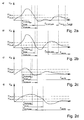
- the Figures 2a to 2d represent, as a function of time, the characteristic aspect of the signals produced by the piezoelectric accelerometer according to the nature of the shock applied to the object.
- the figure 2a corresponds to a valid shock.
- the voltage V IN across the accelerometer begins by exceeding the threshold value V TH, ON . After having grown and passed through a maximum, the voltage V IN begins to decrease. It becomes lower than the threshold value V TH, OFF after a duration T P, ON less than the value T P, ON, MAX and higher than the value T P, ON, MIN . Subsequently, the voltage V IN across the accelerometer is not rebound and remains below the threshold value V TH, ON for a time T P, OFF that will at least equal the value T P, OFF, MIN .
- the shock being recognized as valid, the output of the system becomes active during a duration T OUT . When the output of the system becomes inactive, the system enters a silent mode during a time T MUTE during which said system does not accept a new shock.
- the figure 2b corresponds to a non-valid shock typically produced by a contact of the object against a hard surface.
- the voltage V IN begins to present a satisfactory profile as the figure 2a until, having decreased below the threshold value V TH, OFF, it does not start to grow again and exceed the threshold value V TH, ON after a period T P, OFF less than the value T P, OFF, MIN .
- the system enters its mute mode in which it accepts no new shock for a time T MUTE .
- the Figure 2c corresponds to another invalid shock because too weak. Indeed, if the voltage V IN across the accelerometer begins to exceed the threshold value V TH, ON , it decreases rapidly and becomes lower than the second threshold value after a period T P, ON which is less than T P, ON, MIN , which is not enough. The signal is therefore not recognized as valid and is rejected by the system which enters a silent mode in which it does not accept a new shock for a duration T MUTE .
- figure 2d also corresponds to a non-valid shock typically produced by a contact of the object against a soft surface or when the user applauds in the case where the object is a wristwatch.
- the voltage V IN remains greater than the second threshold value V TH, OFF for a duration T P, ON greater than the value T P, ON.MAX .
- the signal is therefore not recognized as valid and is rejected by the system which enters the mute mode in which it accepts no new shock for a time T MUTE .
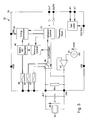
- the figure 3 is a block diagram of the detection circuit.
- this circuit comprises a piezoelectric type accelerometer 34 sold by Murata under the reference PKGS 90LC. Under the effect of a shock, this accelerometer produces a current which is transformed into a voltage signal V IN by its own capacity.
- a capacitor C1 is connected in parallel across this accelerometer. This capacitor C1 which can take different values is mounted outside an integrated circuit 36 and allows the detection circuit 32 to always see the same signal regardless of the application to which said detection circuit 32 is intended. For example, in the case of a watch application, the detection circuit 32 will see the same signal as the case of the watch is plastic or metal.
- a resistor R IN is also connected in parallel across the terminals of the accelerometer 34 but is part of the integrated circuit 36. This resistor is intended to allow at rest, the positive input of a comparator 38 is brought to the same potential as its negative input.
- a follower circuit 40 whose positive input is connected to a reference voltage source 42 generates a voltage between the negative and positive supply potentials, respectively V SS and V DD , of the integrated circuit 36, which voltage is used. to bias one of the terminals of the accelerometer 34 and the negative input of the comparator 38 and whose value will preferably be but not limited to being fixed in the vicinity of 700mV.
- the comparator 38 is a hysteresis comparator having two threshold values respectively V TH, OFF and V TH, ON . Depending on the step of the filtering process where it is located, the voltage V IN across the accelerometer 34 will be compared to one or other of these two threshold values.
- the threshold value V TH, OFF preferably corresponds to a potential difference between the input terminals of the comparator 38 of the order of 0V +/- 5mV, whereas the threshold value V TH, ON can be set near 30mV. +/- 2mV.
- a start circuit 44 controls the engagement of a time base 46 which includes an RC oscillator whose clock frequency is set at 65 kHz.
- This time base 46 provides a clock signal to a generator of durations 48, that is to say a division chain which counts the time and makes it possible to ensure that the duration of the V IN pulse produced by the accelerometer 34 is less than a maximum duration T P, ON, MAX and greater than a minimum duration T P, ON, MIN .
- the minimum durations T P, ON, MIN and maximum T P, ON, MAX are respectively 0,488ms and 5,127ms.
- the duration generator 48 also makes it possible to generate the duration T P, OFF during which the V IN pulse produced by the accelerometer 34 must remain below the threshold value V TH, ON so that the signal is recognized as valid.
- the threshold level of the comparator will be set to V TH, OFF and vice versa.
- the duration T P, OFF has a value of 5.127ms.
- the duration T MUTE during which the system does not accept a new shock is set at 46.8ms.
- a control circuit 50 checks whether the pulse V IN is valid according to the method illustrated in connection with the figure 1 . If this is the case, its output OUT goes to a high level for a duration T OUT determined by the duration generator 48. T OUT therefore determines the duration during which a function remains active or during which the digital output of the control circuit 50 remains applied to an input of a microcontroller. After this time, the output of the control circuit 50 returns to an inactive low level and the system remains insensitive to shocks for an additional duration T MUTE determined by the duration generator 48. If the shock is not recognized as valid, the system immediately goes into its mute state for the duration T MUTE . It will also be noted that the control circuit 50 also has the function of indicating to the comparator 38 which of its two high or low levels V TH, ON or V TH, OFF it must compare with the voltage V IN present at the terminals of the accelerometer 34.
- fuses 52, 54 and 56 are provided which, for a given integrated circuit, make it possible to adjust the thresholds V TH, OFF , V TH, ON and the frequency of the clock circuit 46.
Landscapes
- Physics & Mathematics (AREA)
- Nonlinear Science (AREA)
- General Physics & Mathematics (AREA)
- Electric Clocks (AREA)
Claims (20)
- Verfahren zum Filtern von Signalen (von), die durch einen Beschleunigungsmesser (34) des piezoelektrischen Typs in Reaktion auf die Detektion eines Stoßes, der auf ein Objekt ausgeübt wird, mit dem der Beschleunigungsmesser verbunden ist, erzeugt werden, wobei dieses Verfahren dadurch gekennzeichnet ist, dass sichergestellt ist, dass während eines ersten Schrittes das Signal (VIN), das durch den Beschleunigungsmesser (34) erzeugt wird, nachdem es angewachsen ist und einen ersten Schwellenwert (VTH,ON) durchläuft, nach einer Dauer (TP,ON), die größer als eine minimale Dauer (T P,ON,MIN) und kleiner als eine maximale Dauer (TP,ON,MAX) ist, abnimmt und kleiner als ein zweiter Schwellenwert (VTH,OFF), der kleiner als der erste Schwellenwert (VTH,ON) ist, wird.
- Verfahren nach Anspruch 1, dadurch gekennzeichnet, dass während eines zweiten Schrittes, der auf den ersten Schritt folgt, sichergestellt ist, dass das von dem Beschleunigungsmesser (34) erzeugte Signal (VIN) während einer Dauer, die wenigstens gleich einem dritten vorgegebenen Wert (TP,OFF,MIN) ist, kleiner als der erste Schwellenwert (VTH,ON) bleibt.
- Verfahren nach einem der Ansprüche 1 oder 2, dadurch gekennzeichnet, dass dann, wenn das von dem Beschleunigungsmesser (34) erzeugte Signal (VIN) nach einer Dauer (TP,ON), die kleiner als die minimale Dauer (TP,ON,MIN) ist, größer als der zweite Schwellenwert (VTH,OFF) bleibt, oder wenn das Signal (VIN) größer als der zweite Schwellenwert (VTH,OFF) bleibt, dies jedoch während einer Dauer (TP,ON), die größer als die maximale Dauer (TP,ON,MAX) ist, der Stoß nicht als gültig erkannt wird.
- Verfahren nach einem der vorhergehenden Ansprüche 2 oder 3, dadurch gekennzeichnet, dass dann, wenn das Signal (VIN) nach dem ersten Schritt am Ende einer Zeit, die kleiner als die Dauer (TP,OFF,MIN) ist, wieder größer als der erste Schwellenwert (VTH,ON) wird, der Stoß nicht als gültig erkannt wird.
- Vorrichtung zum Filtern von Signalen (VIN), die von einem Beschleunigungsmesser (34) des piezoelektrischen Typs in Reaktion auf die Detektion eines Stoßes, der auf ein Objekt, mit dem der Beschleunigungsmesser (34) verbunden ist, ausgeübt wird, erzeugt werden, wobei diese Vorrichtung dadurch gekennzeichnet ist, dass sie umfasst:- Vergleichsmittel (38), um den Pegel des von dem Beschleunigungsmesser (34) erzeugten Signals (VIN) mit einem ersten und einem zweiten Schwellenwert (VTH,ON; VTH,OFF) zu vergleichen;
Mittel (44) zum Auslösen einer Zeitbasis (46), die in Betrieb versetzt wird, wenn der Pegel des an die Vergleichsmittel (38) gelieferten Signals (VIN) des Beschleunigungsmessers (34) größer als der erste Schwellenpegel (VTH,ON) ist;- einen Referenzdauer-Generator (48), der durch die Zeitbasis (46) gesteuert wird, und- Mittel (50) zum zeitlichen Steuern des Ausgangspegels (OUT(COMP)) der Vergleichsmittel in Bezug auf die Referenzdauern, die von dem Generator (48) geliefert werden, um zu bestimmen, ob der Stoß gültig ist oder nicht. - Vorrichtung nach Anspruch 5, dadurch gekennzeichnet, dass der Referenzdauer-Generator (48) die folgenden Dauern erzeugt:- eine minimale Dauer (TP,ON,MIN) und eine maximale Dauer (TP,ON,MAX), zwischen denen eine Dauer (TP,ON) enthalten ist, nach der das Signal (VIN) kleiner als ein zweiter Schwellenwert (VTH,OFF) wird, nachdem es den ersten Schwellenwert (VTH,ON) überschritten hat;- einen dritten vorgegebenen Wert (TP,OFF,MIN), währenddessen das Signal (VIN) den ersten Schwellenwert (VTH,ON) nicht erneut überschreiten darf;- eine erste Verzögerungsdauer (TOUT), während der eine Funktion aktiv bleibt oder während der ein digitaler Anteil der Steuerschaltung (50) an einen Eingang eines Mikrocontrollers angelegt bleibt, und- eine zweite Verzögerungsdauer (TMUTE), während der die Filterungsvorrichtung (32) keinen neuen Stoß akzeptiert.
- Vorrichtung nach Anspruch 6, dadurch gekennzeichnet, dass:- die Dauer (TP,ON,MIN) als Wert 0,488 ms hat;- die Dauer (TP,ON,MAX) als Wert 5,127 ms hat;- die Dauer (TP,OFF,MIN) als Wert 5,127 ms hat und- die Dauer (TOUT) als Wert 46,8 ms hat.
- Vorrichtung nach einem der Ansprüche 5 bis 7, dadurch gekennzeichnet, dass sie eine integrierte Schaltung (36) umfasst.
- Vorrichtung nach Anspruch 8, dadurch gekennzeichnet, dass ein Kondensator (C1) zu den Anschlüssen des Beschleunigungsmessers (34) außerhalb der integrierten Schaltung (36) parallelgeschaltet ist, derart, dass die Vergleichsmittel (38) unabhängig von der Eingabe, für die die Filterungsvorrichtung (32) bestimmt ist, stets das gleiche Signal sehen.
- Vorrichtung nach einem der Ansprüche 5 bis 9, dadurch gekennzeichnet, dass die Vergleichsmittel (38) einen Komparator mit Hysterese umfassen, der zwei Schwellenwerte (VTH,OFF bzw. VTH,ON) aufweist.
- Vorrichtung nach Anspruch 10, dadurch gekennzeichnet, dass ein Widerstand (RIN) zu den Anschlüssen des Komparators (38) parallelgeschaltet ist, derart, dass es möglich ist, dann, wenn die Filterungsschaltung (32) in Ruhe ist, die Anschlüsse des Komparators (38) auf demselben Potential liegen.
- Vorrichtung nach einem der Ansprüche 5 bis 11, dadurch gekennzeichnet, dass die Zeitbasis (46) einen RC-Oszillator enthält.
- Vorrichtung nach Anspruch 12, dadurch gekennzeichnet, dass die Taktfrequenz des RC-Oszillators auf 65 kHz festgelegt ist.
- Vorrichtung nach einem der Ansprüche 5 bis 13, dadurch gekennzeichnet, dass der Dauer-Generator (48) eine Teilungskette, die die Zeit abwärts zählt, umfasst.
- Vorrichtung nach einem der Ansprüche 5 bis 14, dadurch gekennzeichnet, dass die Steuermittel (50) außerdem die Funktion haben, den Vergleichsmitteln (38) anzugeben, ob der Hochpegel oder der Tiefpegel (VTH,ON; VTH,OFF) mit der von der Beschleunigungsmesser (34) erzeugten Spannung (VIN) verglichen werden soll.
- Vorrichtung nach einem der Ansprüche 5 bis 15, dadurch gekennzeichnet, dass sie Schmelzsicherungen (52, 54, 56) umfasst, die ermöglichen, die Schwellenwerte (VTH,OF; VTH,ON) und die Taktfrequenz der Zeitbasis (46) einzustellen.
- Vorrichtung nach einem der Ansprüche 7 bis 16, dadurch gekennzeichnet, dass sie eine Folgerschaltung (40) umfasst, die mit einer Referenzspannungsquelle (42) verbunden ist und eine Spannung erzeugt, die zwischen dem negativen und dem positiven Versorgungspotential (VSS bzw. VDD) der integrierten Schaltung (36) liegt, wobei einer der Anschlüsse des Beschleunigungsmessers (34) und des Komparators (38) mit der Spannung vorgespannt wird.
- Vorrichtung nach Anspruch 17, dadurch gekennzeichnet, dass die von der Folgerschaltung (40) erzeugte Spannung in der Umgebung von 700 mV liegt.
- Vorrichtung nach einem der Ansprüche 5 bis 18, dadurch gekennzeichnet, dass der Schwellenwert (VTH,OFF) einer Potentialdifferenz in der Größenordnung von 0 V ± 5 mV entspricht und dass der Schwellenwert (VTH,ON) in der Umgebung von 30 mV ± 2 mV festgelegt werden kann.
- Tragbarer Gegenstand wie etwa eine Armbanduhr, der eine Filterungsvorrichtung nach einem der Ansprüche 5 bis 19 umfasst, dadurch gekennzeichnet, dass dann, wenn die Steuermittel bestimmen, dass während eines ersten Schrittes das Signal (VIN), das von dem Beschleunigungsmesser (34) erzeugt wird, nachdem es angestiegen ist und einen ersten Schwellenwert (VTH,ON) durchlaufen hat, nach einer Dauer (TP,ON), die größer als eine minimale Dauer (TP,ON,MIN) und kleiner als eine maximale Dauer (TP,ON,MAX) ist, abnimmt und kleiner als ein zweiter Schwellenwert (VTH,OFF), der kleiner als der erste Schwellenwert (VTH,ON) ist, wird, der Schluss gezogen wird, dass der auf das Objekt ausgeübte Stoß absichtlich erfolgt, und ein Steuersignal erzeugt wird, um eine Funktion des tragbaren Gegenstands auszulösen.
Priority Applications (2)
| Application Number | Priority Date | Filing Date | Title |
|---|---|---|---|
| EP03021920.8A EP1521364B1 (de) | 2003-09-29 | 2003-09-29 | Verfahren und Vorrichtung zur Filterung von durch einen Piezoelektrischen Beschleunigungsmesser erzeugten Signalen, und Anwendung auf einem tragbaren Gegenstand wie zum Beispiel eine Uhr |
| US10/951,692 US7143012B2 (en) | 2003-09-29 | 2004-09-29 | Method and device for filtering signals produced by an accelerometer of the piezo-electric type, and application to a portable object such as a watch |
Applications Claiming Priority (1)
| Application Number | Priority Date | Filing Date | Title |
|---|---|---|---|
| EP03021920.8A EP1521364B1 (de) | 2003-09-29 | 2003-09-29 | Verfahren und Vorrichtung zur Filterung von durch einen Piezoelektrischen Beschleunigungsmesser erzeugten Signalen, und Anwendung auf einem tragbaren Gegenstand wie zum Beispiel eine Uhr |
Publications (2)
| Publication Number | Publication Date |
|---|---|
| EP1521364A1 EP1521364A1 (de) | 2005-04-06 |
| EP1521364B1 true EP1521364B1 (de) | 2013-08-21 |
Family
ID=34306782
Family Applications (1)
| Application Number | Title | Priority Date | Filing Date |
|---|---|---|---|
| EP03021920.8A Expired - Lifetime EP1521364B1 (de) | 2003-09-29 | 2003-09-29 | Verfahren und Vorrichtung zur Filterung von durch einen Piezoelektrischen Beschleunigungsmesser erzeugten Signalen, und Anwendung auf einem tragbaren Gegenstand wie zum Beispiel eine Uhr |
Country Status (2)
| Country | Link |
|---|---|
| US (1) | US7143012B2 (de) |
| EP (1) | EP1521364B1 (de) |
Families Citing this family (5)
| Publication number | Priority date | Publication date | Assignee | Title |
|---|---|---|---|---|
| US7606552B2 (en) * | 2005-11-10 | 2009-10-20 | Research In Motion Limited | System and method for activating an electronic device |
| FR2940847B1 (fr) * | 2009-01-08 | 2011-07-15 | Legrand France | Dispositif d'interfacage tactile |
| US8612146B2 (en) * | 2010-02-15 | 2013-12-17 | Texas Instruments Incorporated | Accelerometer-aided gyroscope |
| DE102010027160A1 (de) * | 2010-07-14 | 2012-01-19 | Hella Kgaa Hueck & Co. | Möbel mit einer Beleuchtungseinrichtung und Verfahren zum Betreiben einer solchen |
| KR101403457B1 (ko) * | 2013-12-27 | 2014-06-27 | (주)페타리 | 저전력을 이용한 상태 검출 장치 및 방법 |
Family Cites Families (12)
| Publication number | Priority date | Publication date | Assignee | Title |
|---|---|---|---|---|
| US3961271A (en) * | 1975-02-07 | 1976-06-01 | International Telephone And Telegraph Corporation | Pulse width and amplitude screening circuit |
| US4745564B2 (en) * | 1986-02-07 | 2000-07-04 | Us Agriculture | Impact detection apparatus |
| US4763341A (en) * | 1987-02-25 | 1988-08-09 | The Grass Valley Group, Inc. | Digital timing using a state machine |
| US5197489A (en) * | 1991-06-17 | 1993-03-30 | Precision Control Design, Inc. | Activity monitoring apparatus with configurable filters |
| US5982573A (en) * | 1993-12-15 | 1999-11-09 | Hewlett-Packard Company | Disk drive and method for minimizing shock-induced damage |
| US6539336B1 (en) * | 1996-12-12 | 2003-03-25 | Phatrat Technologies, Inc. | Sport monitoring system for determining airtime, speed, power absorbed and other factors such as drop distance |
| EP0738943A1 (de) * | 1995-04-21 | 1996-10-23 | Scubapro EU | Tauchmessgerät, insbesondere Tauchcomputer |
| US5631427A (en) * | 1996-01-16 | 1997-05-20 | Dell Usa, L.P. | Accelerometer-based shock/vibration testing apparatus and associated methods for a portable computer |
| US6138516A (en) * | 1997-12-17 | 2000-10-31 | Weld Star Technology, Inc. | Low-power shock detector and detection method |
| US6553807B2 (en) * | 1999-02-22 | 2003-04-29 | Seagate Technology Llc | Disc drive component level shock tester |
| US6353579B1 (en) * | 2000-08-07 | 2002-03-05 | Timex Group B.V. | Display illumination for an electronic device |
| DE10042270A1 (de) * | 2000-08-29 | 2002-03-14 | Alcatel Sa | Spannungskomparatorschaltung für die Einhüllende einer Wechselspannung und Verfahren dazu |
-
2003
- 2003-09-29 EP EP03021920.8A patent/EP1521364B1/de not_active Expired - Lifetime
-
2004
- 2004-09-29 US US10/951,692 patent/US7143012B2/en not_active Expired - Lifetime
Also Published As
| Publication number | Publication date |
|---|---|
| EP1521364A1 (de) | 2005-04-06 |
| US7143012B2 (en) | 2006-11-28 |
| US20050071133A1 (en) | 2005-03-31 |
Similar Documents
| Publication | Publication Date | Title |
|---|---|---|
| EP0451060B1 (de) | Mp-Netzteil-Aufweck-Schaltung, insbesondere für ferngesteuerte Identifizierung bei Kraftwagen | |
| EP0806710B1 (de) | Stabilisation einer elektronischen Schaltung zur Regelung des mechanischen Gangwerks einer Zeitmessvorrichtung | |
| EP0674247B1 (de) | Uhr mit manueller Bedienung | |
| CH639309A5 (fr) | Machine-outil avec une tete et un dispositif de mesure amovible. | |
| EP0441714A1 (de) | Einrichtung zur Überwachung des Betriebs eines Mikroprozessorsystems oder dergleichen | |
| EP1521364B1 (de) | Verfahren und Vorrichtung zur Filterung von durch einen Piezoelektrischen Beschleunigungsmesser erzeugten Signalen, und Anwendung auf einem tragbaren Gegenstand wie zum Beispiel eine Uhr | |
| EP0058095B1 (de) | Gerät zur Bestimmung der Ankunftszeit von Impulsen mit DME-Verwendungszweck | |
| CH691010A5 (fr) | Appareil électrique fonctionnant à l'aide d'une source photovoltaïque, notamment pièce d'horlogerie. | |
| EP0654604B1 (de) | Verfahren und Vorrichtung einer Spulenzündung mit zusätzlichen Entladungen zur Diagnose | |
| CH690936A5 (fr) | Dispositif de détection ultra-sonore, notamment pour un système de nettoyage de pare-brise à commande automatique. | |
| EP1128239B1 (de) | Tragbares Objekt, insbesondere Uhrwerk, mit piezoelektrischem Transducer zum manuellen Eingeben von Daten | |
| EP1426738B1 (de) | Elektronische Vorrichtung und Verfahren mit darin integriertem kapazitiven Wasserfühler | |
| EP0954770A1 (de) | Uhr mit detektions- und sparvorrichtungen im falle von nicht ausreichender energieversorgung | |
| FR2846479A1 (fr) | Circuit permettant de detecter l'etat d'au moins un interrupteur electrique | |
| EP2320567A1 (de) | Schaltung zur Verbindung von Sensoren | |
| EP0616272B1 (de) | Schaltung zur Unterdrückung der Prelleffekte beim Schliessen und Öffnen eines Kontaktes in einen Uhr | |
| EP0327989B1 (de) | Regelkreis für einen Schrittmotor, insbesondere für Uhren | |
| EP3809210B1 (de) | Elektronische vorrichtung zur steuerung der stromversorgung eines elektrohaushaltsgeräts | |
| EP0853265B1 (de) | Mit photovoltaischer Zelle funktionierendes elektronisches Gerät, insbesondere Zeitmesswerk | |
| EP0849609B1 (de) | Ultraschalldetektionsvorrichtung, insbesondere für eine Scheibenwischeranlage mit automatischer Kontrolle | |
| FR3072177B1 (fr) | Procede de synchronisation pour la lecture d’un etat d’un contact electrique de vehicule automobile | |
| EP1235122A1 (de) | Tragbares Objekt mit Vorrichtungen zur Aktivierung einer elektronischen Funktion sowie Steuerungsverfahren für diese Funktion | |
| FR3034883B1 (fr) | Dispositif de commande renforce d'un equipement electrique | |
| EP1343059B1 (de) | Verfahren und Vorrichtung zur Beleuchtung eines elektronischen oder elektromechanischen Gerätes | |
| FR2577364A1 (fr) | Dispositif electronique de commande par variation de capacite |
Legal Events
| Date | Code | Title | Description |
|---|---|---|---|
| PUAI | Public reference made under article 153(3) epc to a published international application that has entered the european phase |
Free format text: ORIGINAL CODE: 0009012 |
|
| AK | Designated contracting states |
Kind code of ref document: A1 Designated state(s): AT BE BG CH CY CZ DE DK EE ES FI FR GB GR HU IE IT LI LU MC NL PT RO SE SI SK TR |
|
| AX | Request for extension of the european patent |
Extension state: AL LT LV MK |
|
| 17P | Request for examination filed |
Effective date: 20051006 |
|
| AKX | Designation fees paid |
Designated state(s): AT BE BG CH CY CZ DE DK EE ES FI FR GB GR HU IE IT LI LU MC NL PT RO SE SI SK TR |
|
| GRAJ | Information related to disapproval of communication of intention to grant by the applicant or resumption of examination proceedings by the epo deleted |
Free format text: ORIGINAL CODE: EPIDOSDIGR1 |
|
| GRAP | Despatch of communication of intention to grant a patent |
Free format text: ORIGINAL CODE: EPIDOSNIGR1 |
|
| GRAP | Despatch of communication of intention to grant a patent |
Free format text: ORIGINAL CODE: EPIDOSNIGR1 |
|
| INTG | Intention to grant announced |
Effective date: 20130409 |
|
| RIC1 | Information provided on ipc code assigned before grant |
Ipc: G01R 19/165 20060101ALI20130327BHEP Ipc: H03K 5/1254 20060101AFI20130327BHEP |
|
| GRAS | Grant fee paid |
Free format text: ORIGINAL CODE: EPIDOSNIGR3 |
|
| GRAA | (expected) grant |
Free format text: ORIGINAL CODE: 0009210 |
|
| AK | Designated contracting states |
Kind code of ref document: B1 Designated state(s): AT BE BG CH CY CZ DE DK EE ES FI FR GB GR HU IE IT LI LU MC NL PT RO SE SI SK TR |
|
| REG | Reference to a national code |
Ref country code: GB Ref legal event code: FG4D Free format text: NOT ENGLISH |
|
| REG | Reference to a national code |
Ref country code: CH Ref legal event code: EP |
|
| REG | Reference to a national code |
Ref country code: CH Ref legal event code: NV Representative=s name: ICB INGENIEURS CONSEILS EN BREVETS SA, CH |
|
| REG | Reference to a national code |
Ref country code: AT Ref legal event code: REF Ref document number: 628600 Country of ref document: AT Kind code of ref document: T Effective date: 20130915 |
|
| REG | Reference to a national code |
Ref country code: IE Ref legal event code: FG4D Free format text: LANGUAGE OF EP DOCUMENT: FRENCH |
|
| REG | Reference to a national code |
Ref country code: DE Ref legal event code: R096 Ref document number: 60344770 Country of ref document: DE Effective date: 20131010 |
|
| REG | Reference to a national code |
Ref country code: AT Ref legal event code: MK05 Ref document number: 628600 Country of ref document: AT Kind code of ref document: T Effective date: 20130821 Ref country code: NL Ref legal event code: VDEP Effective date: 20130821 |
|
| PG25 | Lapsed in a contracting state [announced via postgrant information from national office to epo] |
Ref country code: CY Free format text: LAPSE BECAUSE OF FAILURE TO SUBMIT A TRANSLATION OF THE DESCRIPTION OR TO PAY THE FEE WITHIN THE PRESCRIBED TIME-LIMIT Effective date: 20130703 Ref country code: AT Free format text: LAPSE BECAUSE OF FAILURE TO SUBMIT A TRANSLATION OF THE DESCRIPTION OR TO PAY THE FEE WITHIN THE PRESCRIBED TIME-LIMIT Effective date: 20130821 Ref country code: PT Free format text: LAPSE BECAUSE OF FAILURE TO SUBMIT A TRANSLATION OF THE DESCRIPTION OR TO PAY THE FEE WITHIN THE PRESCRIBED TIME-LIMIT Effective date: 20131223 Ref country code: SE Free format text: LAPSE BECAUSE OF FAILURE TO SUBMIT A TRANSLATION OF THE DESCRIPTION OR TO PAY THE FEE WITHIN THE PRESCRIBED TIME-LIMIT Effective date: 20130821 |
|
| PG25 | Lapsed in a contracting state [announced via postgrant information from national office to epo] |
Ref country code: GR Free format text: LAPSE BECAUSE OF FAILURE TO SUBMIT A TRANSLATION OF THE DESCRIPTION OR TO PAY THE FEE WITHIN THE PRESCRIBED TIME-LIMIT Effective date: 20131122 Ref country code: FI Free format text: LAPSE BECAUSE OF FAILURE TO SUBMIT A TRANSLATION OF THE DESCRIPTION OR TO PAY THE FEE WITHIN THE PRESCRIBED TIME-LIMIT Effective date: 20130821 Ref country code: SI Free format text: LAPSE BECAUSE OF FAILURE TO SUBMIT A TRANSLATION OF THE DESCRIPTION OR TO PAY THE FEE WITHIN THE PRESCRIBED TIME-LIMIT Effective date: 20130821 |
|
| BERE | Be: lapsed |
Owner name: EM MICROELECTRONIC-MARIN SA Effective date: 20130930 |
|
| PG25 | Lapsed in a contracting state [announced via postgrant information from national office to epo] |
Ref country code: CY Free format text: LAPSE BECAUSE OF FAILURE TO SUBMIT A TRANSLATION OF THE DESCRIPTION OR TO PAY THE FEE WITHIN THE PRESCRIBED TIME-LIMIT Effective date: 20130821 |
|
| PG25 | Lapsed in a contracting state [announced via postgrant information from national office to epo] |
Ref country code: EE Free format text: LAPSE BECAUSE OF FAILURE TO SUBMIT A TRANSLATION OF THE DESCRIPTION OR TO PAY THE FEE WITHIN THE PRESCRIBED TIME-LIMIT Effective date: 20130821 Ref country code: CZ Free format text: LAPSE BECAUSE OF FAILURE TO SUBMIT A TRANSLATION OF THE DESCRIPTION OR TO PAY THE FEE WITHIN THE PRESCRIBED TIME-LIMIT Effective date: 20130821 Ref country code: SK Free format text: LAPSE BECAUSE OF FAILURE TO SUBMIT A TRANSLATION OF THE DESCRIPTION OR TO PAY THE FEE WITHIN THE PRESCRIBED TIME-LIMIT Effective date: 20130821 Ref country code: NL Free format text: LAPSE BECAUSE OF FAILURE TO SUBMIT A TRANSLATION OF THE DESCRIPTION OR TO PAY THE FEE WITHIN THE PRESCRIBED TIME-LIMIT Effective date: 20130821 Ref country code: DK Free format text: LAPSE BECAUSE OF FAILURE TO SUBMIT A TRANSLATION OF THE DESCRIPTION OR TO PAY THE FEE WITHIN THE PRESCRIBED TIME-LIMIT Effective date: 20130821 Ref country code: RO Free format text: LAPSE BECAUSE OF FAILURE TO SUBMIT A TRANSLATION OF THE DESCRIPTION OR TO PAY THE FEE WITHIN THE PRESCRIBED TIME-LIMIT Effective date: 20130821 |
|
| PG25 | Lapsed in a contracting state [announced via postgrant information from national office to epo] |
Ref country code: MC Free format text: LAPSE BECAUSE OF FAILURE TO SUBMIT A TRANSLATION OF THE DESCRIPTION OR TO PAY THE FEE WITHIN THE PRESCRIBED TIME-LIMIT Effective date: 20130821 Ref country code: ES Free format text: LAPSE BECAUSE OF FAILURE TO SUBMIT A TRANSLATION OF THE DESCRIPTION OR TO PAY THE FEE WITHIN THE PRESCRIBED TIME-LIMIT Effective date: 20130821 Ref country code: IT Free format text: LAPSE BECAUSE OF FAILURE TO SUBMIT A TRANSLATION OF THE DESCRIPTION OR TO PAY THE FEE WITHIN THE PRESCRIBED TIME-LIMIT Effective date: 20130821 |
|
| PLBE | No opposition filed within time limit |
Free format text: ORIGINAL CODE: 0009261 |
|
| STAA | Information on the status of an ep patent application or granted ep patent |
Free format text: STATUS: NO OPPOSITION FILED WITHIN TIME LIMIT |
|
| REG | Reference to a national code |
Ref country code: IE Ref legal event code: MM4A |
|
| GBPC | Gb: european patent ceased through non-payment of renewal fee |
Effective date: 20131121 |
|
| 26N | No opposition filed |
Effective date: 20140522 |
|
| PG25 | Lapsed in a contracting state [announced via postgrant information from national office to epo] |
Ref country code: IE Free format text: LAPSE BECAUSE OF NON-PAYMENT OF DUE FEES Effective date: 20130929 Ref country code: BE Free format text: LAPSE BECAUSE OF NON-PAYMENT OF DUE FEES Effective date: 20130930 |
|
| REG | Reference to a national code |
Ref country code: DE Ref legal event code: R097 Ref document number: 60344770 Country of ref document: DE Effective date: 20140522 |
|
| PG25 | Lapsed in a contracting state [announced via postgrant information from national office to epo] |
Ref country code: GB Free format text: LAPSE BECAUSE OF NON-PAYMENT OF DUE FEES Effective date: 20131121 |
|
| PG25 | Lapsed in a contracting state [announced via postgrant information from national office to epo] |
Ref country code: TR Free format text: LAPSE BECAUSE OF FAILURE TO SUBMIT A TRANSLATION OF THE DESCRIPTION OR TO PAY THE FEE WITHIN THE PRESCRIBED TIME-LIMIT Effective date: 20130821 |
|
| PG25 | Lapsed in a contracting state [announced via postgrant information from national office to epo] |
Ref country code: HU Free format text: LAPSE BECAUSE OF FAILURE TO SUBMIT A TRANSLATION OF THE DESCRIPTION OR TO PAY THE FEE WITHIN THE PRESCRIBED TIME-LIMIT; INVALID AB INITIO Effective date: 20030929 Ref country code: LU Free format text: LAPSE BECAUSE OF NON-PAYMENT OF DUE FEES Effective date: 20130929 Ref country code: BG Free format text: LAPSE BECAUSE OF FAILURE TO SUBMIT A TRANSLATION OF THE DESCRIPTION OR TO PAY THE FEE WITHIN THE PRESCRIBED TIME-LIMIT Effective date: 20130821 |
|
| REG | Reference to a national code |
Ref country code: FR Ref legal event code: PLFP Year of fee payment: 14 |
|
| REG | Reference to a national code |
Ref country code: FR Ref legal event code: PLFP Year of fee payment: 15 |
|
| REG | Reference to a national code |
Ref country code: FR Ref legal event code: PLFP Year of fee payment: 16 |
|
| PGFP | Annual fee paid to national office [announced via postgrant information from national office to epo] |
Ref country code: DE Payment date: 20200819 Year of fee payment: 18 Ref country code: FR Payment date: 20200819 Year of fee payment: 18 |
|
| PGFP | Annual fee paid to national office [announced via postgrant information from national office to epo] |
Ref country code: CH Payment date: 20200819 Year of fee payment: 18 |
|
| REG | Reference to a national code |
Ref country code: DE Ref legal event code: R119 Ref document number: 60344770 Country of ref document: DE |
|
| REG | Reference to a national code |
Ref country code: CH Ref legal event code: PL |
|
| PG25 | Lapsed in a contracting state [announced via postgrant information from national office to epo] |
Ref country code: FR Free format text: LAPSE BECAUSE OF NON-PAYMENT OF DUE FEES Effective date: 20210930 Ref country code: DE Free format text: LAPSE BECAUSE OF NON-PAYMENT OF DUE FEES Effective date: 20220401 |
|
| PG25 | Lapsed in a contracting state [announced via postgrant information from national office to epo] |
Ref country code: LI Free format text: LAPSE BECAUSE OF NON-PAYMENT OF DUE FEES Effective date: 20210930 Ref country code: CH Free format text: LAPSE BECAUSE OF NON-PAYMENT OF DUE FEES Effective date: 20210930 |