EP1343059B1 - Verfahren und Vorrichtung zur Beleuchtung eines elektronischen oder elektromechanischen Gerätes - Google Patents
Verfahren und Vorrichtung zur Beleuchtung eines elektronischen oder elektromechanischen Gerätes Download PDFInfo
- Publication number
- EP1343059B1 EP1343059B1 EP02075879A EP02075879A EP1343059B1 EP 1343059 B1 EP1343059 B1 EP 1343059B1 EP 02075879 A EP02075879 A EP 02075879A EP 02075879 A EP02075879 A EP 02075879A EP 1343059 B1 EP1343059 B1 EP 1343059B1
- Authority
- EP
- European Patent Office
- Prior art keywords
- light source
- lighting
- lighting device
- light
- ambient
- Prior art date
- Legal status (The legal status is an assumption and is not a legal conclusion. Google has not performed a legal analysis and makes no representation as to the accuracy of the status listed.)
- Expired - Lifetime
Links
- 238000000034 method Methods 0.000 title claims description 14
- 239000003990 capacitor Substances 0.000 claims description 51
- 238000005286 illumination Methods 0.000 claims description 29
- 230000006870 function Effects 0.000 claims description 21
- 238000005259 measurement Methods 0.000 claims description 13
- 239000004973 liquid crystal related substance Substances 0.000 claims description 8
- 210000002858 crystal cell Anatomy 0.000 claims description 7
- 230000004297 night vision Effects 0.000 claims description 4
- 210000004027 cell Anatomy 0.000 claims description 3
- 230000003287 optical effect Effects 0.000 claims description 3
- 230000001360 synchronised effect Effects 0.000 claims description 3
- 238000007599 discharging Methods 0.000 claims description 2
- 230000005540 biological transmission Effects 0.000 claims 1
- 230000000694 effects Effects 0.000 description 4
- 230000004438 eyesight Effects 0.000 description 4
- 238000001514 detection method Methods 0.000 description 3
- 238000010586 diagram Methods 0.000 description 3
- 230000008033 biological extinction Effects 0.000 description 2
- 238000010276 construction Methods 0.000 description 2
- 238000004519 manufacturing process Methods 0.000 description 2
- 230000004048 modification Effects 0.000 description 2
- 238000012986 modification Methods 0.000 description 2
- 241000397921 Turbellaria Species 0.000 description 1
- 230000006978 adaptation Effects 0.000 description 1
- 230000003111 delayed effect Effects 0.000 description 1
- 230000005611 electricity Effects 0.000 description 1
- 238000004146 energy storage Methods 0.000 description 1
- 230000006355 external stress Effects 0.000 description 1
- 230000002349 favourable effect Effects 0.000 description 1
- 230000010354 integration Effects 0.000 description 1
- 230000002441 reversible effect Effects 0.000 description 1
- 230000007704 transition Effects 0.000 description 1
Images
Classifications
-
- G—PHYSICS
- G04—HOROLOGY
- G04G—ELECTRONIC TIME-PIECES
- G04G9/00—Visual time or date indication means
- G04G9/0017—Visual time or date indication means in which the light emitting display elements may be activated at will or are controlled in accordance with the ambient light
-
- H—ELECTRICITY
- H05—ELECTRIC TECHNIQUES NOT OTHERWISE PROVIDED FOR
- H05B—ELECTRIC HEATING; ELECTRIC LIGHT SOURCES NOT OTHERWISE PROVIDED FOR; CIRCUIT ARRANGEMENTS FOR ELECTRIC LIGHT SOURCES, IN GENERAL
- H05B45/00—Circuit arrangements for operating light-emitting diodes [LED]
-
- G—PHYSICS
- G04—HOROLOGY
- G04G—ELECTRONIC TIME-PIECES
- G04G9/00—Visual time or date indication means
- G04G9/0023—Visual time or date indication means by light valves in general
- G04G9/0029—Details
- G04G9/0047—Details electrical, e.g. selection or application of the operating voltage
- G04G9/0052—Details electrical, e.g. selection or application of the operating voltage using means to adjust the display in accordance with the ambient light, e.g. switching or controlling a supplementary light source
-
- H—ELECTRICITY
- H05—ELECTRIC TECHNIQUES NOT OTHERWISE PROVIDED FOR
- H05B—ELECTRIC HEATING; ELECTRIC LIGHT SOURCES NOT OTHERWISE PROVIDED FOR; CIRCUIT ARRANGEMENTS FOR ELECTRIC LIGHT SOURCES, IN GENERAL
- H05B44/00—Circuit arrangements for operating electroluminescent light sources
Definitions
- the present invention relates to a device for providing illumination of a portable electronic device such as a wristwatch to facilitate reading the information provided by this device for a user.
- the present invention also relates to a method for implementing such a device.
- Watches whose dial is illuminated with a light source to allow a user to read the time in the dark have been known for many, many years. These watches are distinguished by the intensity of the illumination provided by the light source. For some of them, the light source strongly illuminates the dial of the watch. This may be advantageous in the case where a seller wishes to demonstrate the qualities of his product to a potential buyer and present to the latter the appearance of his watch in case of night use. The user can thus, despite the clarity prevailing in the point of sale, perceive the display of the watch in the illuminated state. On the other hand, if the user of the watch wants to check the time during the night, the high intensity of the lighting may dazzle him.
- this solution has the significant disadvantage of being a strong energy consumer, which is a serious handicap in the case of portable electronic objects of small dimensions such as a watch whose energy storage capacity is necessarily limited.
- it has been proposed to illuminate the watches more weakly but still sufficiently, of course, so that the user of such a watch can read hourly or other information in the dark.
- This second solution has the main merit of being economical from the point of view of electricity consumption.
- it is practically impossible, unless you retire to a dimly lit place, to demonstrate at the point of sale the qualities of the watch's illumination, because this illumination is too weak to be perceived at all. day.
- a new step has been taken in the state of the art by proposing, as is done, for example, in the patent US 4,995,016 on behalf of the company Seikosha, to provide the watch with a light sensor capable of detecting the different levels of intensity of the ambient light and to adapt, according to the level of detected brightness, the illumination of the device of display which is provided with the watch.
- Such a device makes it possible to no longer need to choose, during the construction of the watch, between an intense or weak illumination, for example the display device of the data provided by said watch. So when the ambient illumination is low (in the dark or the penumbra), the illumination of the display device is itself weak, which, from the point of view of the electrical consumption, is very favorable and allows despite everything watch user to consult it at any time, especially in the middle of the night. On the other hand, when the ambient illumination is intense, the light sensor deactivates the lighting means of the watch.
- a shadow produced, for example, by the sleeve of a shirt distorts the measurement of the degree of ambient brightness.
- the skilled person has no choice but to increase the detection area. But such a measure greatly affects the aesthetic appearance of the watch and increases the size of it.
- the object of the present invention is to remedy the drawbacks of the prior art as well as others by providing a lighting device for a portable electronic device which makes it possible to control the illumination of data in a safe and inexpensive manner. displayed by the electronic device according to the intensity of the ambient light.
- the present invention relates to a lighting device as defined in claim 1.
- the present invention provides a lighting device whose light source is able both to illuminate the data display device of the apparatus it equips and to detect the degree of intensity of the device. ambient lighting.
- the present invention therefore makes it possible to no longer have recourse to an independent luminous intensity sensor which is easily understood. very advantageous in that it is thus possible to limit the number of components used, to simplify the construction and thus to limit costs.
- the reliability of a lighting device according to the invention is improved over that of similar devices known from the prior art.
- the lighting device according to the invention can advantageously be used in combination with the optical elements used to illuminate the display device such as those described in the application for EP-A-0 860 755 .
- these optical elements which are used to distribute the light produced by the light source on the surface, for example the dial of a watch, can be used reversibly to collect ambient light under the principle that the paths optics traversed by light are reversible.
- the use, in combination, of the light source and the elements originally used to diffuse light produced by said light source to collect the ambient light makes it possible to provide the sensor with more reliable information as to the degree of intensity of the light. the ambient brightness than if one used the sensor alone.
- This sensor comprises, in fact, a limited active surface and the detection signal that it provides can be easily disturbed by a temporary shadow.
- the light intensity provided by the light source is adapted to the intensity of the measured ambient light.
- the lighting device if the lighting device is activated while the device that it equips, in particular a timepiece of the wristwatch type, is in full light, said lighting device will provide a strong illumination.
- a seller of a jewelery will be able to demonstrate the characteristics of the watch to his client and to show him what it will look like when the customer uses his watch for example during the night.
- the lighting device is activated in a dark place, it will provide less illumination than in daylight. The user will not be dazzled if he consults his watch during the night, and power consumption will be limited, which increases the life of the batteries that power the watch.
- the time necessary for the human eye to accustom itself to the darkness is taken into account.
- the lighting device will consider that the user's vision has not yet adapted to the new conditions ambient lighting and will strongly illuminate the display device of the watch.
- the lighting device will shine weakly.
- the present invention also relates to a method for illuminating a display device as defined in claim 18.
- the present invention proceeds from the general inventive idea of using the same light source, not only to illuminate the display device of an electronic or electromechanical device such as a wristwatch, but also as a detector of degree of ambient brightness to match the brightness of the display device illumination to the surrounding conditions.
- a detector of degree of ambient brightness to match the brightness of the display device illumination to the surrounding conditions.
- the present invention will be described in connection with an electronic device of the wristwatch type. It goes without saying that the invention is not limited by the type of display device used. It may just as well be a dial above which needles move as a liquid crystal cell. Similarly, the invention is not limited to the horological field and can be applied to any type of portable device such as a measuring device, a wireless phone or laptop or other.
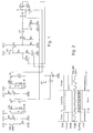
- the light-emitting diode D3 better known by its English name “Light-Emitting Diode” or "LED”, does not play the role of lighting means but, instead, operates in a mode in which it detects the degree of ambient light.
- LED Light-Emitting Diode
- the diode D3, connected to the gate of a transistor T1 thus constitutes with the latter a measuring stage operating in the manner of a current generator whose intensity will depend on the degree of ambient light.
- This provides a current source controlled by LED D3.
- the current produced by this current source flows through a resistor R1 which is connected to the drain of the transistor T1 and which makes it possible to create a voltage drop proportional to the current produced by the current generator.
- a voltage which is a function, on the one hand, of the current produced by the current source controlled by the diode D3, and on the other hand of the value of the resistor R1 itself.
- the choice of the value of the resistor R1 will allow to set a voltage threshold below which the diode D3, when requested, will produce intense lighting, and beyond beyond which the same diode D3 will produce a limited illumination.
- interruption means comprising a transistor T2 are connected to the common point between the transistor T1 and the resistor R1.
- this transistor T2 is always conductive and thus makes it possible to quickly apply the voltage present across said resistor R1 to a capacitor C3.
- This capacitor C3 is connected in parallel with the resistor R1 via a non-return diode D1 which prevents said capacitor C3 from being discharged through the resistor R1.
- the capacitor C3 is associated with a resistor R9 with which it constitutes an RC circuit whose constant of time determines the speed at which the capacitor C3 can discharge through the resistor R9.
- This RC circuit thus constitutes a storage stage which will store a state corresponding to a low or high level of ambient light as a function of the electrical signal produced by the measurement stage. It will be seen later that the value of the time constant of the circuit formed by the capacitor C3 and the resistor R9 is adjusted as a function of the time which is necessary for human vision to adapt to changes in the ambient illumination.
- the elements described so far thus define two time constants.
- the first of these constants corresponds to the very short time required to charge the capacitor C3 via the non-return diode D1, the latter having a very low resistance.
- the second time constant defined by the elements described above corresponds to the time that is necessary for the capacitor C3 to discharge into the resistor R9. This time is longer than the time required to charge the capacitor C3 and is adjusted according to the parameters of human vision as already mentioned. Accordingly, when the device according to the invention is in intense ambient lighting conditions, the current generator that is the LED D3 and the transistor T1 associated with it will charge the capacitor C3 very quickly. If, then, the device according to the invention goes into an environment where the ambient illumination is lower, the capacitor C3 will gradually discharge through the resistor R9.
- the RC circuit formed by the capacitor C3 and the resistor R9 is connected to the logic input D of a flip-flop 1.
- This flip-flop 1 constitutes a stage which, when a signal intended to control the ignition of the light source is produced, adapts the intensity of the light supplied by said light source according to the electrical state stored in the storage stage. More precisely, this flip-flop 1 will consider that its input D is at a logic high level "1" or low "0" depending on whether the voltage applied to this input is greater than a first given value, for example 1.7 volts, or less than a second given value, for example 1.2 volts.
- the flip-flop 1 has the function of applying, without modification, the logic state in which its input D is located at its output Q under the effect of an external bias.
- this external stress takes the form of a pressure on a push button PB1 which just put t1 (see figure 2 , "start” curve) the output Q of a timing circuit 2 at a high level "1".
- the output Q of the timer 2 is connected directly to the clock input CLK of the flip-flop 1.
- the Q output of timer 2 is also connected to the gate of transistor T2.
- the transistor T2 is conducting throughout the duration of the idle phase of the device according to the invention, and the capacitor C3 is connected to the current generator formed by the light emitting diode D3 and the transistor T1 via the non-return diode D1 and said transistor T2.
- the storage stage capacitor C3, resistor R9 of the measurement stage must be decoupled immediately. or integration (diode D3, transistor T1, resistor R1) so as not to distort the state of charge of said capacitor C3. This is the role of the signal generated at the output Q of the timer 2 which opens the transistor T2.
- the transistor T3 controlling the lighting is turned on at time t2 only (see figure 2 curve "LED"), that is to say with a small delay time t1 moment where the push button PB1 is actuated.
- This delay is introduced by an RC circuit consisting of a capacitor C1 and a resistor R3 arranged between the timer 2 and the transistor T3.
- This delayed ignition of the diode D3 makes it possible to ensure that the state of the electric charge accumulated in the capacitor C3 is not changed.
- the logical high or low level of the Q output of flip-flop 1 is represented on the "ligthing" curve of the figure 2 .
- Two horizontal bold lines indicate the logic state "0" or "1" of the Q output of flip-flop 2.
- the logic state of output Q is a function of the state of charge of capacitor C3 at time t1 where push button PB1 is pressed. Indeed, as long as the diode D3 functions as a sensor, the voltage across the capacitor C3 fluctuates as a function of the variations in the intensity of the surrounding light (see FIG. figure 2 curve "Vlight").
- the state of charge of the capacitor C3 freezes and remains substantially the same throughout the duration of the time delay, although the illumination conditions can continue to fluctuate as this is indicated in dashed lines on the "Vlight" curve of the figure 2 . Indeed, because of its time constant, the capacitor C3 slowly discharges in comparison with the duration of the delay signal which corresponds to the duration during which the light emitting diode D3 remains on. At the end of the delay, the capacitor C3 is powered again and quickly regains a charge level corresponding to ambient lighting conditions.
- the logic high or low level of the Q output of flip-flop 1 is applied to the gate of a transistor T6.
- the transistor T6 remains open and the diode D3 is supplied with a minimum current through two resistors R4 and R5 connected in series between said diode D3. and said transistor T6.
- the transistor T6 closes and the diode D3 is then supplied with a maximum current through the single resistor R5. Indeed, when the transistor T6 is conductive, it virtually bypasses the resistance R4 insofar as the value of its internal resistance is very small compared to that of R4.
- the logic state of the Q output of the timer returns to "0".
- the transistor T3 opens, causing the extinction of the diode D3.
- the transistor T2 closes again, so that the capacitor C3 is again connected to the current source stage formed by the diode D3 and the transistor T1 and that its state of charge gradually returns to a level corresponding to the intensity of the ambient light.
- a second timer 4 resets the logic output Q of the flip-flop 1 (see FIG. figure 2 , "reset" curve).
- the transistor T3 In the standby state of the device, the transistor T3 is open because the light-emitting diode D3 must not be electrically powered. Conversely, the transistor T2 is closed and thus passing so that the voltage present across the resistor R1 can be applied across the capacitor C3 and thus allows the load of the latter. It is recalled that the voltage across the resistor R1 results from the current flowing through it and which is produced by the light emitting diode D3 and the transistor T1 operating as a current generator controlled by the ambient brightness. It is easy to understand that the state of charge of the capacitor C3 is a function of the potential drop at the common point between the drain of the transistor T1 and the resistor R1.
- the value of the resistor R1 will determine the value of the voltage applied to the logic input D of the flip-flop 1 and allow it to decide whether its logic input D is at a high level “1” or low “0 ". Depending on whether the logic input D of flip-flop 1 is at "0" or "1” at the moment when the push-button PB1 is actuated, this will determine the intensity of the electric current supplying the diode D3 and therefore the intensity low or high, the illumination produced by said diode D3.
- the device according to the invention being in the light, suppose that one actuates the push button PB1.
- the state of charge of the capacitor C3 is at a high level, so that the logic state of the input D of the flip-flop 1 is at its high level "1".
- the output Q of the timing circuit 2 goes to "1" and controls the transfer of the logic state "1" of the input D of the flip-flop 1 to the Q output of the latter.
- the timing circuit 2 controls the opening of the transistor T2 so that the state of charge of the capacitor C3 is not distorted by the ignition of the light-emitting diode D3.
- the timing circuit 2 controls the closing of the transistor T3 so that the diode D3 can be supplied with electric current.
- the diode D3, however, is energized only briefly after the pusher PB1 has been actuated, this delay being generated by an RC circuit which consists of a capacitor C1 and a resistor R3 and allowing, there also, to ensure that the state of the charge of the capacitor C3 will not be changed by the ignition of the diode D3.
- the high level "1" of the Q output of the flip-flop 2 is applied to the gate of the transistor T6 to make the latter conductive, so that the current that will feed the diode D3 is limited only by the resistor R5. The lighting of the diode D3 will therefore be maximum.
- This function is especially useful when a seller of a jewelry store wishes to present to a customer the appearance of the watch when illuminated in dim light. Indeed, despite the clarity that prevails in the point of sale, the diode D3 shine bright enough for the customer to perceive the lighting of said watch.
- the logic output Q of said timer 2 goes to zero.
- the transistor T3 opens, causing the extinction of the diode D3, and the transistor T2 closes, so that the capacitor C3 gradually returns to a state of charge corresponding to the ambient brightness.
- the device according to the invention will be in a situation in which the potential drop created by the resistance R1 which is a function of the degree of intensity of the Ambient brightness will be less than the potential of capacitor C3.
- the current generator formed by the photoluminescent diode D3 and the transistor T1 can not recharge the capacitor C3 and the latter will begin to gradually discharge through the resistor R9.
- the rate at which the capacitor C3 discharges is set by the time constant of the circuit constituted by said capacitor C3 and the resistor R9. This is a parameter that can be adjusted according to the values of C3 and R9.
- the value of the time constant of the circuit C3, R9 will be of the order of a few minutes. It is indeed a duration which corresponds to the average time necessary for the human eye to accustom itself to the darkness when the person comes from a strongly lit environment.
- the push-button PB1 before the state of charge of the capacitor C3 has reached the value of the potential drop at the common point between the transistor T1 and the resistor R1, the state of the logic input D of flip-flop 1 will be high and diode D3 will shine strongly.
- the user actuates the pusher PB1 while the capacitor C3 has discharged through the resistor R9 and the voltage at its terminals corresponds to the voltage across the resistor R1, in this case the state the logic input D of the flip-flop 1 will be low and the light-emitting diode D3 will glow weakly.
- This feature of the invention advantageously allows the user to read the indications provided by his watch in all circumstances. Thus, if the user suddenly switches from lightness to dim light and it operates shortly after the pushbutton PB1, the light-emitting diode D3 will shine strongly to allow him to read the information displayed by his watch because his vision will not be fully accustomed to the darkness.
- the present invention is not limited to the embodiments that have just been described, and that various modifications and simple variants can be envisaged without departing from the scope of the present invention.
- the values of the resistors can be programmed by the user in order to adjust the charging and discharging times of the capacitors and thus the adaptation times of the illumination to the day and night vision conditions.
- Another advantageous embodiment is to use an electronic circuit that pulses a liquid crystal cell to improve the readability and contrast of the display. Indeed, if one measures the contrast of the display of a liquid crystal cell integrated in a watch, there is a beat of this contrast synchronized with the addressing signal of the electrodes of said cell. Thus, if the pulsed illumination is synchronized with the addressing of the liquid crystal cell in an optimized manner, the observer will only perceive the maximum display contrast.
Landscapes
- Physics & Mathematics (AREA)
- General Physics & Mathematics (AREA)
- Engineering & Computer Science (AREA)
- Microelectronics & Electronic Packaging (AREA)
- Electric Clocks (AREA)
Claims (24)
- Beleuchtungsvorrichtung für ein elektronisches oder elektromechanisches Gerät wie etwa ein Zeitmessgerät des Typs Armbanduhr, das eine Vorrichtung zum Anzeigen einer zeitlichen oder anderen Information enthält, wobei diese Beleuchtungsvorrichtung eine Lichtquelle (D3) umfasst, um die Anzeigevorrichtung zu beleuchten, wobei diese Lichtquelle (D3) außerdem die Intensität des Umgebungslichts messen kann, wobei die Beleuchtungsvorrichtung umfasst:- eine Messstufe (D3, T1), die dazu ausgelegt ist, ein elektrisches Signal zu liefern, das Umgebungsbeleuchtungsbedingungen repräsentiert;- eine Speicherstufe (C3, R9), die dazu ausgelegt ist, einen elektrischen Zustand, der einem geringen oder einem hohen Helligkeitspegel entspricht, in Abhängigkeit von dem von der Messstufe erzeugten elektrischen Signal zu speichern, wobei diese Speicherstufe einen Kondensator (C3) umfasst, der zu den Anschlüssen eines Widerstands (R9) parallelgeschaltet ist, derart, dass eine RC-Schaltung gebildet ist, deren Wert der Zeitkonstante entsprechend den Werten der Kapazität des Kondensators (C3) und des Widerstands (R9) bestimmt ist, und- eine Stufe (1), die dann, wenn ein Signal (Tempo) erzeugt wird, das dazu bestimmt ist, das Einschalten der Lichtquelle zu steuern, dazu ausgelegt ist, die Intensität des von der Lichtquelle (D3) gelieferten Lichts als Funktion des in der Speicherstufe (C3, R9) gespeicherten elektrischen Zustands anzupassen;wobei zwischen der Messstufe und der Speicherstufe Unterbrechungsmittel (T2) angeordnet sind, wobei diese Unterbrechungsmittel so lange durchschalten, wie die Lichtquelle die Intensität des Umgebungslichts misst, und bei Empfang des Signals, das das Einschalten der Lichtquelle (D3) steuert, unterbrechen, damit der Ladezustand der Speicherstufe nicht gestört wird.
- Beleuchtungsvorrichtung nach Anspruch 1, dadurch gekennzeichnet, dass die von der Lichtquelle gelieferte Lichtintensität eine Funktion der gemessenen Intensität des Umgebungslichts ist.
- Beleuchtungsvorrichtung nach einem der Ansprüche 1 oder 2, dadurch gekennzeichnet, dass die Lichtquelle den Intensitätsgrad der Umgebungshelligkeit während der Perioden, in der sie nicht für die Beleuchtung verwendet wird, messen kann.
- Beleuchtungsvorrichtung nach einem der Ansprüche 1 bis 3, dadurch gekennzeichnet, dass die Messstufe die Lichtquelle umfasst, der ein Transistor (T1) zugeordnet ist, um einen durch die Intensität des Umgebungslichts gesteuerten Stromgenerator zu bilden.
- Beleuchtungsvorrichtung nach einem der Ansprüche 1 bis 5, dadurch gekennzeichnet, dass der Wert der Zeitkonstante der Zeit entspricht, die das menschliche Auge benötigt, um sich an die Dunkelheit zu gewöhnen.
- Beleuchtungsvorrichtung nach einem der Ansprüche 1 bis 5, dadurch gekennzeichnet, dass die Steuerschaltung zum Einschalten der Lichtquelle eine Kippschaltung (1) umfasst, die hinter der Schaltung angeordnet ist, die durch den Kondensator (C3) und den Widerstand (R9) gebildet ist, wobei der hohe oder tiefe Zustand eines logischen Eingangs D der Kippschaltung (1) eine Funktion des Zustands der Ladung des Kondensators (C3) ist, wobei dieser Zustand bei Empfang des Steuersignals, das dazu bestimmt ist, das Einschalten der Lichtquelle zu steuern, an einen logischen Ausgang Q dieser Kippschaltung (1) übertragen wird, wobei dann der Ausgang Q der Kippschaltung (1) Mittel steuert, die die Lichtquelle in Abhängigkeit vom hohen oder tiefen logischen Zustand des Ausgangs Q mit einem mehr oder weniger starken Strom versorgen können.
- Beleuchtungsvorrichtung nach Anspruch 6, dadurch gekennzeichnet, dass die Mittel zum Steuern der Intensität des Stroms, der die Lichtquelle versorgt, wenigstens zwei in Reihe geschaltete Widerstände (R4, R5) umfassen, wovon einer (R4) durch einen an seinen Anschlüssen angebrachten Transistor (T6) kurzgeschlossen werden kann, wenn dieser durchschaltet.
- Beleuchtungsvorrichtung nach einem der Ansprüche 6 oder 7, dadurch gekennzeichnet, dass das Steuersignal durch eine Verzögerungsschaltung (2) erzeugt wird, wobei diese Verzögerungsschaltung (2) das Schließen von Unterbrechungsmitteln steuert, was ermöglicht, die Lichtquelle mit einer Versorgungsquelle zu verbinden, und die Zeit bestimmt, während der die Lichtquelle eingeschaltet bleibt.
- Beleuchtungsvorrichtung nach Anspruch 8, dadurch gekennzeichnet, dass die Unterbrechungsmittel einen zweiten Transistor (T3) umfassen.
- Beleuchtungsvorrichtung nach einem der Ansprüche 8 oder 9, dadurch gekennzeichnet, dass die Lichtquelle bei Aussenden des Signals zum Steuern des Einschaltens der Lichtquelle mit einer Zeitverzögerung versorgt wird.
- Beleuchtungsvorrichtung nach Anspruch 10, dadurch gekennzeichnet, dass die Zeitverzögerung durch eine zweite RC-Schaltung erzeugt wird, die einen zweiten Kondensator (C1) und einen zweiten Widerstand (R3) umfasst.
- Beleuchtungsvorrichtung nach einem der Ansprüche 1 bis 11, dadurch gekennzeichnet, dass die Speicherstufe von der Messstufe durch eine Rücklaufverhinderungsdiode (D1) getrennt ist, die verhindert, dass sich der Kondensator (C3) in die Messstufe entlädt.
- Beleuchtungsvorrichtung nach einem der Ansprüche 1 bis 12, dadurch gekennzeichnet, dass die Unterbrechungsmittel einen dritten Transistor (T2) umfassen.
- Beleuchtungsvorrichtung nach einem der Ansprüche 6 bis 13, dadurch gekennzeichnet, dass beim Ausschalten der Lichtquelle eine zweite Verzögerungsschaltung (4) den logischen Ausgang Q der Kippschaltung (1) auf null zurückstellt.
- Beleuchtungsvorrichtung nach einem der Ansprüche 1 bis 14, dadurch gekennzeichnet, dass die Lichtquelle eine Elektrolumineszenzdiode (D3) ist.
- Beleuchtungsvorrichtung nach einem der Ansprüche 1 bis 15, dadurch gekennzeichnet, dass die Anzeigevorrichtung eine Flüssigkristallzelle, ein Zifferblatt oder Zeiger oder aber eine Kombination aus wenigstens zwei dieser Elemente umfasst.
- Beleuchtungsvorrichtung nach einem der Ansprüche 1 bis 16, dadurch gekennzeichnet, dass die Beleuchtungsvorrichtung in Kombination mit optischen Elementen verwendet werden kann, die verwendet werden, um das von der Lichtquelle erzeugte Licht auf die gesamte Beleuchtungsvorrichtung zu verteilen.
- Verfahren zum Beleuchten einer Vorrichtung zum Anzeigen einer zeitlichen oder anderen Information für ein elektronisches oder elektromechanisches Gerät wie etwa ein Zeitmessgerät des Typs Armbanduhr, die eine Lichtquelle (D3) umfasst, um die Anzeigevorrichtung zu beleuchten, wobei diese Beleuchtungsquelle außerdem verwendet wird, um die Intensität des Umgebungslichts zu messen, wobei dieses Verfahren die Schritte umfasst, die darin bestehen:- die Umgebungsbeleuchtungsbedingungen zu messen und ein diese Umgebungsbeleuchtungsbedingungen repräsentierendes elektrisches Signal zu liefern;- einen elektrischen Zustand, der einem niedrigen oder hohen Helligkeitspegel entspricht, der eine Funktion des von der Stufe zum Messen der Umgebungsbeleuchtungsbedingungen gelieferten elektrischen Signals ist, mittels einer Speicherstufe zu speichern, die einen zu den Anschlüssen eines Widerstands (R9) parallelgeschalteten Kondensator (C3) umfasst, derart, dass eine RC-Schaltung gebildet ist, deren Wert der Zeitkonstante als Funktion der Werte der Kapazität des Kondensators (C3) und des Widerstands (R9) bestimmt ist, und- die Intensität des von der Lichtquelle (D3) gelieferten Lichts als Funktion des gespeicherten elektrischen Zustands anzupassen, wenn ein Signal (Tempo), das dazu bestimmt ist, das Einschalten der Lichtquelle zu steuern, erzeugt wird,wobei das Verfahren außerdem den Schritt umfasst, der darin besteht, Unterbrechungsmittel (T2), die zwischen den Mitteln (D3, T1) zum Messen der Umgebungsbeleuchtungsbedingungen und den Mitteln (C3, R9) zum Speichern des Umgebungshelligkeitspegels angeordnet sind, so lange durchzuschalten, wie die Lichtquelle die Intensität des Umgebungslichts misst, und die Verbindung zwischen den Messmitteln (D3, Tal) und den Speichermitteln (C3, R9) bei Empfang des Signals, das das Einschalten der Lichtquelle steuert, zu unterbrechen, um den Ladezustand der Speichermittel nicht zu stören.
- Verfahren nach Anspruch 18, dadurch gekennzeichnet, dass die Anzeigevorrichtung als Funktion des Umgebungsbeleuchtungsgrads mehr oder weniger stark beleuchtet wird.
- Verfahren nach Anspruch 19, dadurch gekennzeichnet, dass die Anzeigevorrichtung stark beleuchtet wird, wenn sie sich in einer hellen Umgebung befindet.
- Verfahren nach einem der Ansprüche 18 bis 20, dadurch gekennzeichnet, dass dann, wenn das Gerät von einer sehr hellen Umgebung in eine Umgebung gebracht wird, in der Dämmerlicht oder Dunkelheit herrscht, und dann, wenn gewünscht ist, die Anzeigevorrichtung zu beleuchten, bevor der Zeitpunkt erreicht ist, zu dem sich das menschliche Auge an die Dunkelheit gewöhnt hat, die Anzeigevorrichtung mit einer Intensität beleuchtet wird, als ob sie sich in einer hellen Umgebung befände.
- Verfahren nach einem der Ansprüche 18 bis 21, dadurch gekennzeichnet, dass dann, wenn das Gerät von einem sehr hellen Ort zu einem Ort gebracht wird, in dem Dämmerlicht oder Dunkelheit herrscht, und dann, wenn gewünscht ist, die Anzeigevorrichtung zu beleuchten, nachdem der Zeitpunkt erreicht ist, zu dem sich das menschliche Auge an die Dunkelheit gewöhnt hat, die Anzeigevorrichtung schwach beleuchtet wird.
- Verfahren nach einem der Ansprüche 20 bis 22, dadurch gekennzeichnet, dass die Zeit für die Anpassung der Beleuchtung an die Tag- oder Nachtsichtbedingungen programmiert werden kann.
- Verfahren nach einem der Ansprüche 18 bis 23, wobei die Anzeigevorrichtung eine Flüssigkristallzelle ist, dadurch gekennzeichnet, dass die Beleuchtung mit der Anzeigefrequenz der Flüssigkristallzelle synchronisiert ist, derart, dass die Zelle zu dem Zeitpunkt beleuchtet wird, zu dem ihr Kontrast optimal ist.
Priority Applications (1)
| Application Number | Priority Date | Filing Date | Title |
|---|---|---|---|
| EP02075879A EP1343059B1 (de) | 2002-03-05 | 2002-03-05 | Verfahren und Vorrichtung zur Beleuchtung eines elektronischen oder elektromechanischen Gerätes |
Applications Claiming Priority (1)
| Application Number | Priority Date | Filing Date | Title |
|---|---|---|---|
| EP02075879A EP1343059B1 (de) | 2002-03-05 | 2002-03-05 | Verfahren und Vorrichtung zur Beleuchtung eines elektronischen oder elektromechanischen Gerätes |
Publications (2)
| Publication Number | Publication Date |
|---|---|
| EP1343059A1 EP1343059A1 (de) | 2003-09-10 |
| EP1343059B1 true EP1343059B1 (de) | 2011-12-21 |
Family
ID=27741209
Family Applications (1)
| Application Number | Title | Priority Date | Filing Date |
|---|---|---|---|
| EP02075879A Expired - Lifetime EP1343059B1 (de) | 2002-03-05 | 2002-03-05 | Verfahren und Vorrichtung zur Beleuchtung eines elektronischen oder elektromechanischen Gerätes |
Country Status (1)
| Country | Link |
|---|---|
| EP (1) | EP1343059B1 (de) |
Families Citing this family (1)
| Publication number | Priority date | Publication date | Assignee | Title |
|---|---|---|---|---|
| CN107241827B (zh) * | 2017-06-07 | 2023-09-12 | 欧普照明股份有限公司 | 一种开关电路 |
Family Cites Families (3)
| Publication number | Priority date | Publication date | Assignee | Title |
|---|---|---|---|---|
| US3757511A (en) * | 1971-05-17 | 1973-09-11 | Motorola Inc | Light emitting diode display for electronic timepiece |
| JPH02107991A (ja) * | 1988-10-17 | 1990-04-19 | Seikosha Co Ltd | 発光装置付時計 |
| FI110211B (fi) * | 1999-12-31 | 2002-12-13 | Nokia Corp | Valaistusolosuhteiden mittaus |
-
2002
- 2002-03-05 EP EP02075879A patent/EP1343059B1/de not_active Expired - Lifetime
Also Published As
| Publication number | Publication date |
|---|---|
| EP1343059A1 (de) | 2003-09-10 |
Similar Documents
| Publication | Publication Date | Title |
|---|---|---|
| CH616822B5 (de) | ||
| FR2463470A1 (fr) | Unite d'affichage a cristaux liquides pour vehicules automobiles | |
| FR2783629A1 (fr) | Afficheur a cristal liquide a matrice active | |
| US7550930B2 (en) | Method and device for lighting an electronic or electromechanical apparatus | |
| EP0744675B1 (de) | Zeitmessinstrument insbesondere elektrische Armbanduhr analoger Art | |
| EP3620866B1 (de) | Aktive beleuchtungsvorrichtung, die am handgelenk einer person tragbar ist | |
| EP1343059B1 (de) | Verfahren und Vorrichtung zur Beleuchtung eines elektronischen oder elektromechanischen Gerätes | |
| EP2746869B1 (de) | Elektrischer Solar-Aufzugmechanismus für automatische Armbanduhr | |
| EP1875454B1 (de) | Treiber und dessen verfahren zur steuerung einer segment-flüssigkristallanzeigevorrichtung | |
| FR2847685A1 (fr) | Horloge multifonctions | |
| EP0221363A1 (de) | Elektronische Analoguhr | |
| EP3835890B1 (de) | Digitale anzeigevorrichtung, die zwei übereinander angeordnete anzeigezellen umfasst | |
| WO1998033098A1 (fr) | Montre comportant des moyens de detection et de sauvegarde en cas d'insuffisance de la source d'alimentation | |
| EP3299906B1 (de) | Elektronische uhr mit zwei zeigern vom analogen typ | |
| CH621027B5 (de) | ||
| EP0243232A1 (de) | Vorrichtung zum Antrieb eines Mobile | |
| CH716362B1 (fr) | Dispositif d'affichage digital comprenant deux cellules d'affichage superposées et pièce d'horlogerie comprenant un tel dispositif d'affichage. | |
| FR2553509A3 (fr) | Dispositif de mesure comportant un dispositif d'affichage passif | |
| CH715296B1 (fr) | Dispositif d`éclairage actif portable au poignet d`une personne | |
| HK1058972B (en) | Method and device for lighting an electronic or electromechanical apparatus | |
| FR2476341A1 (fr) | Circuit pour un appareil, en particulier une pendule electronique, comprenant un circuit de controle de la batterie | |
| CH720364A2 (fr) | Cadran de montre comprenant un dispositif autonome de détermination d'un évènement magnétique | |
| CH720375A2 (fr) | Pièce d'horlogerie à illumination localisée | |
| CH712944A2 (fr) | Pièce d'horlogerie électronique à deux aiguilles du type analogique. | |
| CH707406A2 (fr) | Remontoir électrique solaire pour montre automatique. |
Legal Events
| Date | Code | Title | Description |
|---|---|---|---|
| PUAI | Public reference made under article 153(3) epc to a published international application that has entered the european phase |
Free format text: ORIGINAL CODE: 0009012 |
|
| AK | Designated contracting states |
Kind code of ref document: A1 Designated state(s): AT BE CH CY DE DK ES FI FR GB GR IE IT LI LU MC NL PT SE TR |
|
| AX | Request for extension of the european patent |
Extension state: AL LT LV MK RO SI |
|
| 17P | Request for examination filed |
Effective date: 20040310 |
|
| AKX | Designation fees paid |
Designated state(s): CH DE FR GB LI |
|
| RBV | Designated contracting states (corrected) |
Designated state(s): AT BE CH CY DE DK ES FI FR GB GR IE IT LI LU MC NL PT SE TR |
|
| RBV | Designated contracting states (corrected) |
Designated state(s): CH DE FR GB LI |
|
| 17Q | First examination report despatched |
Effective date: 20100118 |
|
| GRAP | Despatch of communication of intention to grant a patent |
Free format text: ORIGINAL CODE: EPIDOSNIGR1 |
|
| RTI1 | Title (correction) |
Free format text: METHOD AND MEANS FOR ILLUMINATING AN ELECTRONIC OR AN ELECTROMECHANICAL DEVICE |
|
| GRAS | Grant fee paid |
Free format text: ORIGINAL CODE: EPIDOSNIGR3 |
|
| GRAA | (expected) grant |
Free format text: ORIGINAL CODE: 0009210 |
|
| AK | Designated contracting states |
Kind code of ref document: B1 Designated state(s): CH DE FR GB LI |
|
| REG | Reference to a national code |
Ref country code: GB Ref legal event code: FG4D Free format text: NOT ENGLISH |
|
| REG | Reference to a national code |
Ref country code: CH Ref legal event code: EP |
|
| REG | Reference to a national code |
Ref country code: CH Ref legal event code: NV Representative=s name: ICB INGENIEURS CONSEILS EN BREVETS SA |
|
| REG | Reference to a national code |
Ref country code: DE Ref legal event code: R096 Ref document number: 60241777 Country of ref document: DE Effective date: 20120308 |
|
| PLBE | No opposition filed within time limit |
Free format text: ORIGINAL CODE: 0009261 |
|
| STAA | Information on the status of an ep patent application or granted ep patent |
Free format text: STATUS: NO OPPOSITION FILED WITHIN TIME LIMIT |
|
| 26N | No opposition filed |
Effective date: 20120924 |
|
| GBPC | Gb: european patent ceased through non-payment of renewal fee |
Effective date: 20120321 |
|
| REG | Reference to a national code |
Ref country code: DE Ref legal event code: R097 Ref document number: 60241777 Country of ref document: DE Effective date: 20120924 |
|
| PG25 | Lapsed in a contracting state [announced via postgrant information from national office to epo] |
Ref country code: GB Free format text: LAPSE BECAUSE OF NON-PAYMENT OF DUE FEES Effective date: 20120321 |
|
| REG | Reference to a national code |
Ref country code: FR Ref legal event code: PLFP Year of fee payment: 15 |
|
| PGFP | Annual fee paid to national office [announced via postgrant information from national office to epo] |
Ref country code: DE Payment date: 20160218 Year of fee payment: 15 |
|
| PGFP | Annual fee paid to national office [announced via postgrant information from national office to epo] |
Ref country code: FR Payment date: 20160219 Year of fee payment: 15 |
|
| REG | Reference to a national code |
Ref country code: DE Ref legal event code: R119 Ref document number: 60241777 Country of ref document: DE |
|
| REG | Reference to a national code |
Ref country code: CH Ref legal event code: PFUS Owner name: THE SWATCH GROUP RESEARCH AND DEVELOPMENT LTD , CH Free format text: FORMER OWNER: ASULAB S.A., CH |
|
| REG | Reference to a national code |
Ref country code: FR Ref legal event code: ST Effective date: 20171130 |
|
| PG25 | Lapsed in a contracting state [announced via postgrant information from national office to epo] |
Ref country code: DE Free format text: LAPSE BECAUSE OF NON-PAYMENT OF DUE FEES Effective date: 20171003 Ref country code: FR Free format text: LAPSE BECAUSE OF NON-PAYMENT OF DUE FEES Effective date: 20170331 |
|
| PGFP | Annual fee paid to national office [announced via postgrant information from national office to epo] |
Ref country code: CH Payment date: 20210219 Year of fee payment: 20 |
|
| REG | Reference to a national code |
Ref country code: CH Ref legal event code: PL |