EP1521385A2 - Protocole de sécurité pour contrôleur industriel - Google Patents
Protocole de sécurité pour contrôleur industriel Download PDFInfo
- Publication number
- EP1521385A2 EP1521385A2 EP04022515A EP04022515A EP1521385A2 EP 1521385 A2 EP1521385 A2 EP 1521385A2 EP 04022515 A EP04022515 A EP 04022515A EP 04022515 A EP04022515 A EP 04022515A EP 1521385 A2 EP1521385 A2 EP 1521385A2
- Authority
- EP
- European Patent Office
- Prior art keywords
- message data
- recited
- data
- edc
- message
- Prior art date
- Legal status (The legal status is an assumption and is not a legal conclusion. Google has not performed a legal analysis and makes no representation as to the accuracy of the status listed.)
- Granted
Links
Images

Classifications
-
- H—ELECTRICITY
- H04—ELECTRIC COMMUNICATION TECHNIQUE
- H04L—TRANSMISSION OF DIGITAL INFORMATION, e.g. TELEGRAPHIC COMMUNICATION
- H04L1/00—Arrangements for detecting or preventing errors in the information received
- H04L1/004—Arrangements for detecting or preventing errors in the information received by using forward error control
- H04L1/0056—Systems characterized by the type of code used
- H04L1/0061—Error detection codes
-
- H—ELECTRICITY
- H04—ELECTRIC COMMUNICATION TECHNIQUE
- H04L—TRANSMISSION OF DIGITAL INFORMATION, e.g. TELEGRAPHIC COMMUNICATION
- H04L1/00—Arrangements for detecting or preventing errors in the information received
- H04L1/004—Arrangements for detecting or preventing errors in the information received by using forward error control
- H04L1/0056—Systems characterized by the type of code used
- H04L1/0064—Concatenated codes
- H04L1/0065—Serial concatenated codes
-
- H—ELECTRICITY
- H04—ELECTRIC COMMUNICATION TECHNIQUE
- H04L—TRANSMISSION OF DIGITAL INFORMATION, e.g. TELEGRAPHIC COMMUNICATION
- H04L1/00—Arrangements for detecting or preventing errors in the information received
- H04L1/0078—Avoidance of errors by organising the transmitted data in a format specifically designed to deal with errors, e.g. location
- H04L1/0083—Formatting with frames or packets; Protocol or part of protocol for error control
-
- H—ELECTRICITY
- H04—ELECTRIC COMMUNICATION TECHNIQUE
- H04L—TRANSMISSION OF DIGITAL INFORMATION, e.g. TELEGRAPHIC COMMUNICATION
- H04L1/00—Arrangements for detecting or preventing errors in the information received
- H04L2001/0092—Error control systems characterised by the topology of the transmission link
- H04L2001/0094—Bus
Definitions
- the present invention relates to industrial controllers used for real time control of industrial processes, and in particular, to a high reliability industrial controller appropriate for use in devices intended to protect human health and life.
- Industrial controllers are special purpose computers used in controlling industrial processes. Under the direction of a stored control program, an industrial controller examines a series of inputs reflecting the status of the control process and changes a series of outputs controlling the industrial process.
- the inputs and outputs may be binary, that is, on or off, or analog, providing a value within a continuous range.
- the inputs may be obtained from sensors attached to the controlled equipment and the outputs may be signals to actuators on the controlled equipment.
- Safety systems are systems intended to ensure the safety of humans working in the environment of an industrial process. Such systems may include, but are not limited to, the electronics associated with emergency stop buttons, interlock switches and machine lockouts. Traditionally, safety systems have been implemented by a set of circuits wholly separate from the industrial control system used to control the industrial process with which the safety system is associated. Such safety systems were originally "hard-wired” from switches and relays, some of which may be specialized “safety relays” allowing comparison of redundant signals and providing internal checking of conditions such as welded or stuck contacts. Safety systems may use switches with dual contacts providing an early indication of contact failure, and multiple contacts may be wired to actuators so that the actuators are energized only if multiple contacts close.
- Hard-wired safety systems have proven inadequate as the complexity of industrial processes has increased. This is in part because of the cost of installing and wiring relays and in part because of the difficulty of troubleshooting and maintaining the "program" implemented by the safety system in which the logic can only be changed by rewiring physical relays and switches.
- High reliability refers generally to systems that guard against the propagation of erroneous data or signals to a predetermined high level of probability defined by safety certification standards. Such high reliability is obtained by detecting error or fault conditions and entering into a predetermined fault state. High reliability systems may be distinguished from high availability systems, however, the present invention may be useful in both situations, and therefore as used herein, high reliability should not be considered to exclude high availability systems.
- High reliability controllers are easier to program and have reduced installation costs because of their ability for use of a high-speed serial communication network eliminating long runs of point-to-point wiring.
- the system should be sufficiently robust so as to reliably detect errors in transmitting network messages.
- Efforts have been undertaken to develop a "safety network" which is a high-speed serial communication network providing greater certainty in the transmission of data.
- conventional high-speed serial communication networks commonly used in industrial control are not sufficiently reliable for safety systems. For instance, such networks add a large amount of safety information to each message, which increases the message length and thereby reduces the capacity of the network. This reduced capacity may adversely affect the response time for the industrial controller and/or limit additional reliability enhancing features that might be added to the message to otherwise improve its reliability. If the amount of safety information embedded in the messages of conventional safety networks is decreased, the reliability of error detection is compromised.
- the present invention provides a network-independent, high-reliability communications system by imposing levels of safety on data that is transmitted over the network while reducing the necessary hardware.
- the present invention recognizes that safety in data transmission can be achieved with reduced hardware by providing at least one message of data, and providing a compressed representation of the message.
- one aspect of the invention provides a method of communication between a producer node and a consumer node over a high reliability network.
- a message is prepared at the producer node that includes message data, a first error detection code (EDC) based on the message data using a first protocol, and a second EDC based on the message data using a second protocol different than the first protocol.
- EDC error detection code
- the message is then transmitted to the consumer node.
- the consumer node receives the message over the network and calculates an expected first EDC based on the received message data using the first protocol, and an expected second EDC corresponding to the received message data using the second protocol.
- the first and second EDCs are compared to the received first and second EDCs to determine whether data had been corrupted during the transmission of the message.
- the invention provides a method of communication between a producer node and a consumer node over a high reliability network.
- First actual message data is provided.
- First and second phantom error detection codes are then generated as compressed representations related to the actual message data.
- An overall error detection code is generated as a compressed representation of the first and second phantom error detection codes.
- a message is transmitted from the producer node to the consumer node, the message including the actual message data and the overall error detection code, but not the first and second phantom error detection codes..
- the message is received over the network at the consumer node, which calculates an expected overall error detection code.
- the expected error detection code is compared to the received error detection code to determine whether data had been corrupted during the transmission of the message.
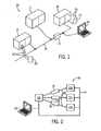
- Fig. 1 is a perspective view of a simplified industrial controller using a standard serial communication network linking a central controller with remote input and output circuits and with a remote configuration terminal, such as may be used in the present invention
- Fig. 2 is a simplified schematic of a network physically connecting nodes of an industrial controller showing messages transmitted from a producer node to consumer nodes;
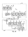
- Fig. 3A is a flowchart showing the path of message flow between a producer node and a consumer node in accordance with the preferred embodiment.
- Fig. 3B is a flowchart showing the path of message flow between a producer node and a consumer node similar to that illustrated in Fig. 3A in accordance with an alternate embodiment
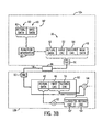
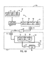
- Fig. 4A is a flowchart showing the path of message flow between a producer node and a consumer node in accordance with an alternate embodiment
- Fig. 4B is a flowchart showing the path of message flow between a producer node and a consumer node in a manner similar to that illustrated in Fig. 4A in accordance with an alternate embodiment.
- the present invention can be part of a "safety system” used to protect human life and limb in the industrial environment. Nevertheless, the term “safety” as used herein is not a representation that the present invention will make an industrial process safe or that other systems will produce unsafe operation. Safety in an industrial process depends on a wide variety of factors outside of the scope of the present invention including: design of the safety system, installation and maintenance of the components of the safety system, and the cooperation and training of individuals using the safety system. Although the present invention is intended to be highly reliable, all physical systems are susceptible to failure and provision must be made for such failure.
- a high reliability industrial control system 10 for implementing a safety system with the present invention includes a controller 11 communicating on a high speed serial network 14 with remote input module 17 and remote output module 19.
- the network 14 may be a standard and commonly available high-speed serial network including but not limited to: Ethernet, DeviceNet, ControlNet, Firewire, FieldBus, or CAN protocol.
- the network 14 may optionally include a bridge 21 translating between different of the above standard or other protocols. As will be understood from the following, the present invention may be easily adapted to applications that use a bridge.
- Input module 17 may accept input signals 23 (on like-designated lines) which are communicated over the network 14 to the industrial controller 11.
- the signals 23 may be processed under a control program implementing a safety system (such as a machine lock-out or emergency stop) and further signals sent to the output module 19 which may produce output signals 25 (on like-designated lines) to an actuator 27.
- a safety system such as a machine lock-out or emergency stop
- the input signals 23 may come from a switch 29 which may be any of a variety of devices producing safety input signals including but not limited to emergency stop switches, interlock switches, light curtains and other proximity detectors.
- the actuator 27 may be a relay, solenoid, motor, enunciator, lamp or other device implementing a safety function.
- a standard computer 20 which may be used as a configuration terminal.
- Nodes 12a-12d may comprise any of switch 29, input module 17, controller 11, output module 19, actuator 27, or any other communications module that is compatible with network 14.
- each of the nodes 12 includes a processor (not shown) for executing a safety protocol program of the preferred embodiment and a standard network interface circuit (NIC) 51 (Figs. 3 and 4) used to provide a low level interface between the given node 12 and the network 14.
- the network 14 may be, for example, one or more standard networks such as Ethernet, DeviceNet, ControlNet, FireWire, or FieldBus.
- the network 14 may use a single or multiple conductor copper media or may use fiber optics, wireless communication technology, or other well-known alternatives. Such networks 14 allow one or more physical media to interconnect each of the nodes 12 with the messages directed by effective addresses contained in the messages.
- Network 14 may be an external network, an internal backplane, or the like.
- a producer node 12a may establish logical connections 18 with other nodes 12b-12d and/or direct messages 16 to particular ones of the other nodes 12b-12d (consumer nodes).
- the nodes 12 may be, for example, components of the high reliability industrial control system 10 including input or output circuits and a centralized controller. While each of nodes 12b-12d are illustrated as receiving nodes, the preferred embodiment will be described with reference only to receiving node 12b, it being appreciated that the present invention is applicable to other receiving nodes.
- Errors may occur in such networks 14 in which a particular message 16 becomes misdirected or otherwise corrupted.
- a misdirected message 16 may be received by a node 12d for which it was not intended. Such misdirection may occur for a number of reasons including alterations in the bit pattern that provide the implicit address of the message 16 as may be caused by external electromagnetic interference.
- a message may reach its intended consumer node though the message data has been corrupted. Such errors may otherwise exhibit no detectable error and, if acted upon, can undermine the reliability of the system.
- EDC error detection code
- the cyclic redundancy code is generally a compressed representation of the message data generated at the producer node.
- the CRC is attached to the message and transmitted over the network to a consumer node.
- An expected CRC is then independently computed at the consumer node based on the message data received, and compared to the CRC embedded in the message.
- a discrepancy between the expected CRC and actual CRC at the consumer module will signify a corruption of the transferred data.
- the reliability of a CRC depends directly on the method used to compute the CRC. While some CRCs have proven more robust than others in detecting various error types, it has been found that some errors nonetheless go systematically undetected.
- the producer node 12a compiles an actual data section 40, which includes actual message data 42 that is to be transmitted over the network 14 to consumer nodes 12b.
- the producer also compiles a complement data section 44 that includes the complement of the message data 46.
- the complement data 46 may be achieved by, for example, inverting each bit of the message data.
- the actual data and complement data sections 40 and 44 are attached to the message portion 16' that is to be further refined into message 16 that is to be transmitted over the network. It should be appreciated that while the actual message data 42 is inverted in accordance with the preferred embodiment, the present invention envisions any systematic alteration of the actual message data 42 to produce the complement message data 46.
- Other miscellaneous data 48 may be included in the message 16' such as a mode byte information and connection data, as understood by those having ordinary skill in the art.
- the function generator 50 includes error detection circuitry which adds an additional error detecting code, which is typically a number sequence that may include, for example, a CRC or other compressed representation of the message transmitted by the producer node 12a that can be used at a later time to detect any errors that occurred during the transmission of data over the network 14.
- generator 50 calculates a first CRC 52 for actual message data 42 based upon a predetermined protocol, and includes CRC 52 in actual data section 40.
- Generator 50 additionally calculates a second CRC 54 for complement message data 46 based upon a predetermined protocol, and includes CRC 54 in complement data section 44. It should thus be appreciated that both CRCs 52 and 54 are said to be "related" or "produced based on" actual message data 42, as the complementary message data 46 has a predetermined relationship to the actual message data.
- the protocol used to calculate CRC 52 is different than that used to compute CRC 54, though the protocol could be the same.
- the protocol used to calculate CRCs 52 and 54 is different, the two CRCs can both be determined based on the actual message data 42 or complementary message data 46. If the protocol used to calculate the CRCs 52 and 54 is the same, CRC 52 would be calculated directly from the actual message data 42, while CRC 54 would be calculated directly from the complementary data 46.
- the protocol used to calculate CRCs 52 and 54 can include any systematic method for compressing data
- the preferred embodiment divides message data 42 and 46 by a predetermined polynomial key to produce a remainder.
- the remainder provides the CRC for the respective data.
- suitable polynomial keys include base-16 0x137 and 0x13b. Accordingly, if the CRCs 52 and 54 are calculated using the same protocol applied to different data sections 42 and 46, either key can be applied. Otherwise, if the CRCs use different protocol, one key would be used to produce CRC 52, while the other key would be used to produce CRC 54.
- the two polynomial keys described herein have been found to produce sufficiently reliable message data, many other polynomial keys could alternatively be used, such as 0x107 and 0x12f, along with others as appreciated by those having ordinary skill in the art.
- the base-16 polynomial keys described above can be converted to a base-2 polynomial.
- the polynomial 0x137 converts to X 8 + X 5 + X 4 + X 2 + X 1 + 1.
- the polynomial 0x137 is divided into the polynomial formed by the bits of actual message data 42. The remainder is expressed as a set of binary bits stored as the first CRC 52.
- the polynomial 0x13b converts to X 8 + X 5 + X 4 + X 3 + X 1 + 1.
- the second CRC 54 is calculated directly from the complementary data 46
- the polynomial 0x13b is divided into the polynomial formed by the bits of complement data 46.
- the remainder is expressed as a set of binary bits, and stored as the second CRC 54.
- the message 16 is then communicated over the network via NIC 51 of producer node 12a, which modifies message 16, typically by adding data according to the particular requirements of the protocol of the network 14.
- the message 16 is received by network interface circuit (NIC) 51' of consumer node 12b, and message sections 40 and 44 are forwarded to a buffer 60.
- the actual message data 42 and complementary data 46 are then fed into a generator 62, while the first and second CRCs 52 and 54 are forwarded to a comparator 64.
- the generator 62 calculates expected first and second CRCs 52' and 54'based on the same protocol used by producer node 12a to determine first and second CRCs 52 and 54, as described above.
- CRCs 52' and 54' are then fed to comparator 64 and are compared against the actual corresponding CRCs 52 and 54. If there is a match, the message 16 is forwarded to the control program. If there is no match, the high-reliability control system 10 can enter a safety state which generally provides a shutting down of portions or all of the high reliability industrial control system 10 according to the predefined safety states for its inputs and outputs.
- Fig. 3B an alternate embodiment to that described an illustrated above with reference to Fig. 3A recognizes that the data transmitted over the network can be reduced, thereby freeing additional bandwidth for actual message data and increasing the efficiency of the network 14.
- producer node 12a can compile a message portion 16' that eliminates complementary data 46, such that the message portion includes actual message data 42 and miscellaneous data 48.
- the message portion 16' is then communicated to function generator 50, which produces first and second CRCs 52 and 54.
- first CRC 52 is preferably produced based on actual message data 42
- second CRC 54 is produced based on message data complementary to actual message data 42.
- the complementary data can be either produced by producer node 12a and forwarded to function generator, or produced at the function generator 50.
- the complementary message data is not part of message 16, the complementary message data is said to be virtual message data.
- CRCs 52 and 54 can be determined using any of the alternative methods described above with reference to Fig. 3A.
- Message 16 including the actual message data 42, first CRC 52, second CRC 54, and miscellaneous data 48, is then communicated over the network 14 via NIC 51 of producer node 12a, which modifies message 16, typically by adding data according to the particular requirements of the protocol of the network 14.
- the message 16 is received by network interface circuit (NIC) 51' of consumer node 12b, and message data 42, 54, and 54 are forwarded to buffer 60.
- the actual message data 42 is then fed into a generator 62, while the first and second CRCs 52 and 54 are forwarded to comparator 64.
- the generator 62 calculates an expected first and second CRCs 52' and 54' based on the same protocol used by producer node 12a to produce CRCs 52 and 54, as described above.
- CRCs 52' and 54' are then fed to comparator 64 and compared against the actual corresponding CRCs 52 and 54. If there is a match, the message 16 is forwarded to the control program. If there is no match, the high reliability control system 10 can enter a safety state as described above.
- the network 14 illustrated in Fig. 3B enables the-safe communication message packets having less safety data than that illustrated in Fig. 3A, thereby increasing the available bandwidth and overall efficiency of the network.
- a message portion 16' is created including an actual message data 74, complement message data 76, and miscellaneous data 78, as discussed above.
- Message portion 16' is sent to the function generator 50 of producer node 12a, which generates an error detection code.
- the error detection code comprises a single overall CRC 80 that is a compressed representation of two CRCs related to actual message data 42, as will be described in more detail below.
- the message 16 is then transmitted to node 12b.
- generator 50 computes a first CRC for the actual message data 42, and a second CRC for the complementary data 46 based on different protocol in the manner described above, and stores the CRCs in a buffer (not shown).
- the first and second CRC's can alternatively be computed using any of the alternative methods described above with reference to Fig. 3A. Unlike the method illustrated and described above with reference to Fig. 3A, however, the computed first and second CRCs are not communicated over the network 14 to consumer node 12b in accordance with the embodiment illustrated in Fig. 4A. Accordingly, these CRCs are referred to herein as phantom CRCs.
- the generator 50 computes an overall CRC 80 that can either be a compressed representation of both phantom CRCs only, or a compressed representation of the phantom CRCs along with actual data 74 and complementary data 76, or any combination thereof, using any technique well known to those having ordinary skill in the art.
- message 16 includes only a single CRC 80, the resulting message 16 is of a smaller size, thereby increasing the available bandwidth for network 14 while providing high reliability data.
- Message 16 is transmitted over the network 14 by producer node 12a via NIC 51, and is received by NIC 51' of consumer node 12b.
- the actual data 74, complementary data 76, and overall CRC 80 are subsequently stored in buffer 60.
- CRC 80 is fed into comparator 64, while actual and complementary data 74 and 76, respectively, are received by a generator 62 which computes an expected CRC 82 based on the protocol used to generate overall CRC 80 at the producer node 12a.
- the expected CRC 82 is forwarded to the comparator 64 and compared to the actual CRC 80. If there is a match, the message 16 is forwarded to the control program. If there is no match, the high reliability control system 10 may enter a safety state which generally provides a shutting down of portions or all of the high reliability industrial control system 10 according to the predefined safety states for its inputs and outputs.
- control system 10 thus provides a high reliability communications network 14 having a reduced bandwidth compared to conventional networks. Data capacity is thus conserved.
- the present invention recognizes that the bandwidth of network 14 illustrated in Fig. 4A can further be increased for actual message data by eliminating the transfer of complementary data 76 from the producer node 12a to the consumer node 12b. Rather, producer node 12a produces compiles message portion 16' including actual data 74, comp data 76, and miscellaneous data 78.
- the function generator 50 receives message portion 16', and calculates the overall CRC based, either directly or indirectly, on the actual data 74 using any of the methods described above. Once the overall CRC is calculated by generator 50, message 16 can be created without complementary data 76.
- the message 16 is then communicated over network 14 via NIC 51 of producer node 12a, which modifies message 16, typically by adding data according to the particular requirements of the protocol of the network.
- the message 16 is received by network interface circuit (NIC) 51' of consumer node 12b, and message sections 74 and 80 are forwarded to buffer 60.
- the actual message data 74 is then fed into a generator 82, while the overall CRC is forwarded to comparator 64.
- the generator 62 can determine, based on actual data 74, an expected overall CRC using the same protocol as producer node 12a to calculate overall CRC 80, as described above.
- the expected CRC is forwarded to comparator 64.
- the expected CRC is compared against the actual CRC 80. If there is a match, the message 16 is forwarded to the control program. If there is no match, the high reliability control system 10 may enter a safety state, as described above.
- producer node 12a can alternatively communicate message portion 16' to function generator 50 without the complementary data 76, such that only actual data 74 and miscellaneous data 78 are received by the function generator.
- the function generator determines the overall CRC 80 using actual data 74 alone.
- the first phantom CRC can be determined directly from the actual data 74
- the second phantom CRC can be determined by altering the actual data to achieve virtual complementary data, and apply the second phantom CRC protocol to the virtual complementary data to determine the second phantom CRC.
- the first and second phantom CRCs are then compressed to provide the overall CRC 80.
- Messages in a high reliability industrial control system are associated with safety messages that enable reliable detection of data errors caused during transmission of the message over the network.
- error detection codes are generated and transmitted along with message data.
- an expected EDC is generated and compared to the EDC transmitted over the network to determine whether any data was corrupted.
Landscapes
- Engineering & Computer Science (AREA)
- Computer Networks & Wireless Communication (AREA)
- Signal Processing (AREA)
- Detection And Prevention Of Errors In Transmission (AREA)
- Communication Control (AREA)
Applications Claiming Priority (2)
| Application Number | Priority Date | Filing Date | Title |
|---|---|---|---|
| US10/675,476 US7203885B2 (en) | 2003-09-30 | 2003-09-30 | Safety protocol for industrial controller |
| US675476 | 2003-09-30 |
Publications (3)
| Publication Number | Publication Date |
|---|---|
| EP1521385A2 true EP1521385A2 (fr) | 2005-04-06 |
| EP1521385A3 EP1521385A3 (fr) | 2007-12-19 |
| EP1521385B1 EP1521385B1 (fr) | 2018-06-06 |
Family
ID=34313991
Family Applications (1)
| Application Number | Title | Priority Date | Filing Date |
|---|---|---|---|
| EP04022515.3A Expired - Lifetime EP1521385B1 (fr) | 2003-09-30 | 2004-09-22 | Protocole de sécurité pour contrôleur industriel |
Country Status (2)
| Country | Link |
|---|---|
| US (1) | US7203885B2 (fr) |
| EP (1) | EP1521385B1 (fr) |
Families Citing this family (26)
| Publication number | Priority date | Publication date | Assignee | Title |
|---|---|---|---|---|
| SE0203819D0 (sv) * | 2002-12-19 | 2002-12-19 | Abb As | Method to increase the safety integrity level of a control system |
| WO2006124650A1 (fr) * | 2005-05-13 | 2006-11-23 | Fisher-Rosemount Systems, Inc. | Communications du procede fieldbus au moyen de la correction d'erreur |
| WO2007076284A2 (fr) * | 2005-12-20 | 2007-07-05 | Fieldbus Foundation | Systeme et procede pour mettre en oeuvre des systemes instrumentes de securite |
| US7539550B2 (en) * | 2006-02-23 | 2009-05-26 | Rockwell Automation Technologies, Inc. | Safety versus availability graphical user interface |
| AT504739B1 (de) * | 2007-01-08 | 2013-09-15 | Bernecker & Rainer Ind Elektronik Gmbh | Anordnung und ein verfahren zur sicheren datenkommunikation über ein nicht sicheres netzwerk |
| DE102007007537A1 (de) * | 2007-02-15 | 2008-08-21 | Siemens Ag | Leitsystem einer technischen Anlage |
| US8656248B2 (en) * | 2007-12-13 | 2014-02-18 | Qualcomm Incorporated | Hierarchical CRC scheme |
| JP5482275B2 (ja) * | 2009-04-01 | 2014-05-07 | セイコーエプソン株式会社 | 記憶装置、基板、液体容器、データ記憶部に書き込むべきデータをホスト回路から受け付ける方法、ホスト回路に対し電気的に接続可能な記憶装置を含むシステム |
| EP2237163B1 (fr) * | 2009-04-01 | 2013-05-01 | Seiko Epson Corporation | Système doté d'une pluralité de dispositifs de mémoire et procédé de transfert de données correspondant |
| CN101856912B (zh) * | 2009-04-01 | 2013-05-22 | 精工爱普生株式会社 | 存储装置和包括能够与主机电路电连接的存储装置的系统 |
| DE102009019089A1 (de) * | 2009-04-20 | 2010-11-04 | Pilz Gmbh & Co. Kg | Verfahren und Vorrichtung zum Erstellen eines Anwenderprogramms für eine Sicherheitssteuerung |
| US9397785B1 (en) | 2010-04-12 | 2016-07-19 | Marvell International Ltd. | Error detection in a signal field of a WLAN frame header |
| US8631174B2 (en) * | 2010-04-21 | 2014-01-14 | General Electric Company | Systems, methods, and apparatus for facilitating communications between an external controller and fieldbus devices |
| JP5556371B2 (ja) | 2010-05-25 | 2014-07-23 | セイコーエプソン株式会社 | 記憶装置、基板、液体容器、データ記憶部に書き込むべきデータをホスト回路から受け付ける方法、ホスト回路に対し電気的に接続可能な記憶装置を含むシステム |
| CN103444114B (zh) | 2011-02-04 | 2017-07-14 | 马维尔国际贸易有限公司 | 用于wlan的控制模式phy |
| DE102011084364A1 (de) | 2011-10-12 | 2013-04-18 | Endress + Hauser Wetzer Gmbh + Co Kg | Verfahren zur telegrammweisen Datenübertragung |
| JP6168503B2 (ja) | 2012-04-03 | 2017-07-26 | マーベル ワールド トレード リミテッド | 方法および装置 |
| WO2014183059A1 (fr) | 2013-05-10 | 2014-11-13 | Marvell World Trade Ltd. | Format de trame de couche physique pour wlan |
| JP6253784B2 (ja) | 2013-09-10 | 2017-12-27 | マーベル ワールド トレード リミテッド | 屋外wlanのための拡張ガードインターバル |
| US10218822B2 (en) | 2013-10-25 | 2019-02-26 | Marvell World Trade Ltd. | Physical layer frame format for WLAN |
| WO2015061729A1 (fr) | 2013-10-25 | 2015-04-30 | Marvell World Trade Ltd. | Mode d'extension de plage wifi |
| US10194006B2 (en) | 2013-10-25 | 2019-01-29 | Marvell World Trade Ltd. | Physical layer frame format for WLAN |
| US11855818B1 (en) | 2014-04-30 | 2023-12-26 | Marvell Asia Pte Ltd | Adaptive orthogonal frequency division multiplexing (OFDM) numerology in a wireless communication network |
| US10256944B1 (en) * | 2015-04-23 | 2019-04-09 | Marvell International Ltd. | Controlling false packet acceptance |
| US11080132B2 (en) * | 2019-07-12 | 2021-08-03 | Micron Technology, Inc. | Generating error checking data for error detection during modification of data in a memory sub-system |
| US12323241B2 (en) * | 2023-07-28 | 2025-06-03 | Qualcomm Incorporated | Separate predictions for video compression for XR |
Citations (1)
| Publication number | Priority date | Publication date | Assignee | Title |
|---|---|---|---|---|
| EP0177690A2 (fr) | 1984-09-11 | 1986-04-16 | International Business Machines Corporation | Méthode de détection et de correction d'erreur par vote majoritaire |
Family Cites Families (12)
| Publication number | Priority date | Publication date | Assignee | Title |
|---|---|---|---|---|
| US4994993A (en) * | 1988-10-26 | 1991-02-19 | Advanced Micro Devices, Inc. | System for detecting and correcting errors generated by arithmetic logic units |
| US5438621A (en) * | 1988-11-02 | 1995-08-01 | Hewlett-Packard Company | DC-free line code and bit and frame synchronization for arbitrary data transmission |
| US5365516A (en) * | 1991-08-16 | 1994-11-15 | Pinpoint Communications, Inc. | Communication system and method for determining the location of a transponder unit |
| US6047396A (en) * | 1992-10-14 | 2000-04-04 | Tm Patents, L.P. | Digital data storage system including phantom bit storage locations |
| US5935268A (en) * | 1997-06-03 | 1999-08-10 | Bay Networks, Inc. | Method and apparatus for generating an error detection code for a modified data packet derived from an original data packet |
| US6598197B1 (en) * | 1997-06-12 | 2003-07-22 | Thomson Licensing S.A. | Method and apparatus for detecting and concealing data errors in stored digital data |
| JP3237700B2 (ja) * | 1997-10-03 | 2001-12-10 | 日本電気株式会社 | 誤り検出方法及び誤り検出システム |
| US6615387B1 (en) * | 1998-09-22 | 2003-09-02 | Seagate Technology Llc | Method and apparatus for error detection |
| US6732317B1 (en) * | 2000-10-23 | 2004-05-04 | Sun Microsystems, Inc. | Apparatus and method for applying multiple CRC generators to CRC calculation |
| US6915444B2 (en) * | 2001-09-12 | 2005-07-05 | Rockwell Automation Technologies, Inc. | Network independent safety protocol for industrial controller using data manipulation techniques |
| MXPA04005228A (es) * | 2001-12-05 | 2004-10-11 | Lg Electronics Inc | Metodo para generar codigos para deteccion de errores y generador de codigos para deteccion de errores. |
| US7047475B2 (en) * | 2003-02-04 | 2006-05-16 | Hewlett-Packard Development Company, L.P. | CRC encoding scheme for conveying status information |
-
2003
- 2003-09-30 US US10/675,476 patent/US7203885B2/en not_active Expired - Lifetime
-
2004
- 2004-09-22 EP EP04022515.3A patent/EP1521385B1/fr not_active Expired - Lifetime
Patent Citations (1)
| Publication number | Priority date | Publication date | Assignee | Title |
|---|---|---|---|---|
| EP0177690A2 (fr) | 1984-09-11 | 1986-04-16 | International Business Machines Corporation | Méthode de détection et de correction d'erreur par vote majoritaire |
Also Published As
| Publication number | Publication date |
|---|---|
| EP1521385B1 (fr) | 2018-06-06 |
| EP1521385A3 (fr) | 2007-12-19 |
| US20050071725A1 (en) | 2005-03-31 |
| US7203885B2 (en) | 2007-04-10 |
Similar Documents
| Publication | Publication Date | Title |
|---|---|---|
| US7203885B2 (en) | Safety protocol for industrial controller | |
| US7076715B2 (en) | Safety network using phantom address information | |
| US6891850B1 (en) | Network independent safety protocol for industrial controller | |
| US7107358B2 (en) | Bridge for an industrial control system using data manipulation techniques | |
| EP2325749B1 (fr) | Protocole de sécurité indépendant du réseau pour contrôleur industriel utilisant des techniques de manipulation de données | |
| EP1240561B1 (fr) | Reseau de securite pour un controleur industriel ayant des imperatifs de largeur de bande reduits | |
| US20030208283A1 (en) | Safety communication on a single backplane | |
| US8321774B2 (en) | Method for fail-safe transmission, safety switching device and control unit | |
| JP6635653B2 (ja) | 送信システムエラー検出および訂正のシステムおよび方法 | |
| US6907542B2 (en) | System, device and method for determining the reliability of data carriers in a failsafe system network | |
| CN108599896A (zh) | 一种基于冗余编码系统的crc校验系统及方法 | |
| US6725419B1 (en) | Automation system and method for operating an automation system | |
| US7418647B2 (en) | Method for data transmission | |
| US20060187932A1 (en) | Method and system for transmitting telegrams | |
| CN101176289B (zh) | 采用纠错的现场总线过程通信 | |
| JP3850841B2 (ja) | データパケットの安全送信の監視方法および装置 | |
| IL297685A (en) | A safety-oriented method and system for performing safety functions | |
| US20250208608A1 (en) | Method and system for error detection and correction | |
| CN101122784A (zh) | 串行异步传输数据的方法和装置 | |
| EP2824572B1 (fr) | Dispositif de sûreté et procédé pour faire fonctionner ledit dispositif | |
| Schiffer et al. | Introduction to DeviceNet safety |
Legal Events
| Date | Code | Title | Description |
|---|---|---|---|
| PUAI | Public reference made under article 153(3) epc to a published international application that has entered the european phase |
Free format text: ORIGINAL CODE: 0009012 |
|
| AK | Designated contracting states |
Kind code of ref document: A2 Designated state(s): AT BE BG CH CY CZ DE DK EE ES FI FR GB GR HU IE IT LI LU MC NL PL PT RO SE SI SK TR |
|
| AX | Request for extension of the european patent |
Extension state: AL HR LT LV MK |
|
| RIC1 | Information provided on ipc code assigned before grant |
Ipc: H04L 12/00 20060101ALI20070926BHEP Ipc: H04L 1/00 20060101AFI20050127BHEP Ipc: H03M 13/00 20060101ALI20070926BHEP |
|
| PUAL | Search report despatched |
Free format text: ORIGINAL CODE: 0009013 |
|
| AK | Designated contracting states |
Kind code of ref document: A3 Designated state(s): AT BE BG CH CY CZ DE DK EE ES FI FR GB GR HU IE IT LI LU MC NL PL PT RO SE SI SK TR |
|
| AX | Request for extension of the european patent |
Extension state: AL HR LT LV MK |
|
| 17P | Request for examination filed |
Effective date: 20080605 |
|
| AKX | Designation fees paid |
Designated state(s): DE FR GB |
|
| 17Q | First examination report despatched |
Effective date: 20111006 |
|
| GRAP | Despatch of communication of intention to grant a patent |
Free format text: ORIGINAL CODE: EPIDOSNIGR1 |
|
| INTG | Intention to grant announced |
Effective date: 20180109 |
|
| GRAS | Grant fee paid |
Free format text: ORIGINAL CODE: EPIDOSNIGR3 |
|
| GRAA | (expected) grant |
Free format text: ORIGINAL CODE: 0009210 |
|
| AK | Designated contracting states |
Kind code of ref document: B1 Designated state(s): DE FR GB |
|
| REG | Reference to a national code |
Ref country code: GB Ref legal event code: FG4D |
|
| REG | Reference to a national code |
Ref country code: DE Ref legal event code: R096 Ref document number: 602004052790 Country of ref document: DE |
|
| REG | Reference to a national code |
Ref country code: FR Ref legal event code: PLFP Year of fee payment: 15 |
|
| RIC2 | Information provided on ipc code assigned after grant |
Ipc: H04L 1/00 20060101AFI20050127BHEP Ipc: H04L 12/00 20060101ALI20070926BHEP Ipc: H03M 13/00 20060101ALI20070926BHEP |
|
| REG | Reference to a national code |
Ref country code: DE Ref legal event code: R097 Ref document number: 602004052790 Country of ref document: DE |
|
| PLBE | No opposition filed within time limit |
Free format text: ORIGINAL CODE: 0009261 |
|
| STAA | Information on the status of an ep patent application or granted ep patent |
Free format text: STATUS: NO OPPOSITION FILED WITHIN TIME LIMIT |
|
| 26N | No opposition filed |
Effective date: 20190307 |
|
| PGFP | Annual fee paid to national office [announced via postgrant information from national office to epo] |
Ref country code: FR Payment date: 20210819 Year of fee payment: 18 |
|
| PGFP | Annual fee paid to national office [announced via postgrant information from national office to epo] |
Ref country code: DE Payment date: 20210818 Year of fee payment: 18 Ref country code: GB Payment date: 20210820 Year of fee payment: 18 |
|
| REG | Reference to a national code |
Ref country code: DE Ref legal event code: R119 Ref document number: 602004052790 Country of ref document: DE |
|
| GBPC | Gb: european patent ceased through non-payment of renewal fee |
Effective date: 20220922 |
|
| P01 | Opt-out of the competence of the unified patent court (upc) registered |
Effective date: 20230404 |
|
| PG25 | Lapsed in a contracting state [announced via postgrant information from national office to epo] |
Ref country code: FR Free format text: LAPSE BECAUSE OF NON-PAYMENT OF DUE FEES Effective date: 20220930 Ref country code: DE Free format text: LAPSE BECAUSE OF NON-PAYMENT OF DUE FEES Effective date: 20230401 |
|
| PG25 | Lapsed in a contracting state [announced via postgrant information from national office to epo] |
Ref country code: GB Free format text: LAPSE BECAUSE OF NON-PAYMENT OF DUE FEES Effective date: 20220922 |