EP2325749B1 - Protocole de sécurité indépendant du réseau pour contrôleur industriel utilisant des techniques de manipulation de données - Google Patents
Protocole de sécurité indépendant du réseau pour contrôleur industriel utilisant des techniques de manipulation de données Download PDFInfo
- Publication number
- EP2325749B1 EP2325749B1 EP10012930A EP10012930A EP2325749B1 EP 2325749 B1 EP2325749 B1 EP 2325749B1 EP 10012930 A EP10012930 A EP 10012930A EP 10012930 A EP10012930 A EP 10012930A EP 2325749 B1 EP2325749 B1 EP 2325749B1
- Authority
- EP
- European Patent Office
- Prior art keywords
- data
- message
- protocol
- safety
- network
- Prior art date
- Legal status (The legal status is an assumption and is not a legal conclusion. Google has not performed a legal analysis and makes no representation as to the accuracy of the status listed.)
- Expired - Lifetime
Links
Images


Classifications
-
- H—ELECTRICITY
- H04—ELECTRIC COMMUNICATION TECHNIQUE
- H04L—TRANSMISSION OF DIGITAL INFORMATION, e.g. TELEGRAPHIC COMMUNICATION
- H04L1/00—Arrangements for detecting or preventing errors in the information received
- H04L1/004—Arrangements for detecting or preventing errors in the information received by using forward error control
- H04L1/0056—Systems characterized by the type of code used
- H04L1/0061—Error detection codes
-
- G—PHYSICS
- G05—CONTROLLING; REGULATING
- G05B—CONTROL OR REGULATING SYSTEMS IN GENERAL; FUNCTIONAL ELEMENTS OF SUCH SYSTEMS; MONITORING OR TESTING ARRANGEMENTS FOR SUCH SYSTEMS OR ELEMENTS
- G05B19/00—Program-control systems
- G05B19/02—Program-control systems electric
- G05B19/04—Program control other than numerical control, i.e. in sequence controllers or logic controllers
- G05B19/042—Program control other than numerical control, i.e. in sequence controllers or logic controllers using digital processors
- G05B19/0423—Input/output
- G05B19/0425—Safety, monitoring
-
- H—ELECTRICITY
- H04—ELECTRIC COMMUNICATION TECHNIQUE
- H04L—TRANSMISSION OF DIGITAL INFORMATION, e.g. TELEGRAPHIC COMMUNICATION
- H04L1/00—Arrangements for detecting or preventing errors in the information received
- H04L1/08—Arrangements for detecting or preventing errors in the information received by repeating transmission, e.g. Verdan system
-
- H—ELECTRICITY
- H04—ELECTRIC COMMUNICATION TECHNIQUE
- H04L—TRANSMISSION OF DIGITAL INFORMATION, e.g. TELEGRAPHIC COMMUNICATION
- H04L1/00—Arrangements for detecting or preventing errors in the information received
- H04L1/12—Arrangements for detecting or preventing errors in the information received by using return channel
- H04L1/14—Arrangements for detecting or preventing errors in the information received by using return channel in which the signals are sent back to the transmitter to be checked ; echo systems
-
- H—ELECTRICITY
- H04—ELECTRIC COMMUNICATION TECHNIQUE
- H04L—TRANSMISSION OF DIGITAL INFORMATION, e.g. TELEGRAPHIC COMMUNICATION
- H04L1/00—Arrangements for detecting or preventing errors in the information received
- H04L1/12—Arrangements for detecting or preventing errors in the information received by using return channel
- H04L1/16—Arrangements for detecting or preventing errors in the information received by using return channel in which the return channel carries supervisory signals, e.g. repetition request signals
- H04L1/18—Automatic repetition systems, e.g. Van Duuren systems
- H04L1/1803—Stop-and-wait protocols
-
- H—ELECTRICITY
- H04—ELECTRIC COMMUNICATION TECHNIQUE
- H04L—TRANSMISSION OF DIGITAL INFORMATION, e.g. TELEGRAPHIC COMMUNICATION
- H04L1/00—Arrangements for detecting or preventing errors in the information received
- H04L1/12—Arrangements for detecting or preventing errors in the information received by using return channel
- H04L1/16—Arrangements for detecting or preventing errors in the information received by using return channel in which the return channel carries supervisory signals, e.g. repetition request signals
- H04L1/18—Automatic repetition systems, e.g. Van Duuren systems
- H04L1/1829—Arrangements specially adapted for the receiver end
- H04L1/1848—Time-out mechanisms
- H04L1/1851—Time-out mechanisms using multiple timers
-
- H—ELECTRICITY
- H04—ELECTRIC COMMUNICATION TECHNIQUE
- H04L—TRANSMISSION OF DIGITAL INFORMATION, e.g. TELEGRAPHIC COMMUNICATION
- H04L1/00—Arrangements for detecting or preventing errors in the information received
- H04L1/12—Arrangements for detecting or preventing errors in the information received by using return channel
- H04L1/16—Arrangements for detecting or preventing errors in the information received by using return channel in which the return channel carries supervisory signals, e.g. repetition request signals
- H04L1/18—Automatic repetition systems, e.g. Van Duuren systems
- H04L1/1829—Arrangements specially adapted for the receiver end
- H04L1/1858—Transmission or retransmission of more than one copy of acknowledgement message
-
- H—ELECTRICITY
- H04—ELECTRIC COMMUNICATION TECHNIQUE
- H04L—TRANSMISSION OF DIGITAL INFORMATION, e.g. TELEGRAPHIC COMMUNICATION
- H04L1/00—Arrangements for detecting or preventing errors in the information received
- H04L1/12—Arrangements for detecting or preventing errors in the information received by using return channel
- H04L1/16—Arrangements for detecting or preventing errors in the information received by using return channel in which the return channel carries supervisory signals, e.g. repetition request signals
- H04L1/18—Automatic repetition systems, e.g. Van Duuren systems
- H04L1/1867—Arrangements specially adapted for the transmitter end
- H04L1/188—Time-out mechanisms
- H04L1/1883—Time-out mechanisms using multiple timers
-
- H—ELECTRICITY
- H04—ELECTRIC COMMUNICATION TECHNIQUE
- H04L—TRANSMISSION OF DIGITAL INFORMATION, e.g. TELEGRAPHIC COMMUNICATION
- H04L1/00—Arrangements for detecting or preventing errors in the information received
- H04L1/22—Arrangements for detecting or preventing errors in the information received using redundant apparatus to increase reliability
-
- G—PHYSICS
- G05—CONTROLLING; REGULATING
- G05B—CONTROL OR REGULATING SYSTEMS IN GENERAL; FUNCTIONAL ELEMENTS OF SUCH SYSTEMS; MONITORING OR TESTING ARRANGEMENTS FOR SUCH SYSTEMS OR ELEMENTS
- G05B2219/00—Program-control systems
- G05B2219/20—Pc systems
- G05B2219/25—Pc structure of the system
- G05B2219/25153—Checking communication
-
- G—PHYSICS
- G05—CONTROLLING; REGULATING
- G05B—CONTROL OR REGULATING SYSTEMS IN GENERAL; FUNCTIONAL ELEMENTS OF SUCH SYSTEMS; MONITORING OR TESTING ARRANGEMENTS FOR SUCH SYSTEMS OR ELEMENTS
- G05B2219/00—Program-control systems
- G05B2219/20—Pc systems
- G05B2219/25—Pc structure of the system
- G05B2219/25163—Transmit twice, redundant, same data on different channels, check each channel
-
- G—PHYSICS
- G05—CONTROLLING; REGULATING
- G05B—CONTROL OR REGULATING SYSTEMS IN GENERAL; FUNCTIONAL ELEMENTS OF SUCH SYSTEMS; MONITORING OR TESTING ARRANGEMENTS FOR SUCH SYSTEMS OR ELEMENTS
- G05B2219/00—Program-control systems
- G05B2219/20—Pc systems
- G05B2219/25—Pc structure of the system
- G05B2219/25228—Scheduling communication on bus
-
- H—ELECTRICITY
- H04—ELECTRIC COMMUNICATION TECHNIQUE
- H04L—TRANSMISSION OF DIGITAL INFORMATION, e.g. TELEGRAPHIC COMMUNICATION
- H04L1/00—Arrangements for detecting or preventing errors in the information received
- H04L1/12—Arrangements for detecting or preventing errors in the information received by using return channel
- H04L1/16—Arrangements for detecting or preventing errors in the information received by using return channel in which the return channel carries supervisory signals, e.g. repetition request signals
-
- H—ELECTRICITY
- H04—ELECTRIC COMMUNICATION TECHNIQUE
- H04L—TRANSMISSION OF DIGITAL INFORMATION, e.g. TELEGRAPHIC COMMUNICATION
- H04L1/00—Arrangements for detecting or preventing errors in the information received
- H04L1/12—Arrangements for detecting or preventing errors in the information received by using return channel
- H04L2001/125—Arrangements for preventing errors in the return channel
Definitions
- the present invention relates to industrial controllers used for real-time control of industrial processes, and in particular to high-reliability industrial controllers appropriate for use in devices intended to protect human life and health.
- “High reliability” refers generally to systems that guard against the propagation of erroneous data or signals by detecting error or fault conditions and signaling their occurrence and/or entering into a predetermined fault state.
- High reliability systems may be distinguished from high availability systems, however, the present invention may be useful in both such systems and therefore, as used herein, high reliability should not be considered to exclude high availability systems.
- Industrial controllers are special purpose computers used in controlling industrial processes. Under the direction of a stored control program, an industrial controller examines a series of inputs reflecting the status of the controlled process and changes a series of outputs controlling the industrial process.
- the inputs and outputs may be binary, that is, on or off, or analog, providing a value within a continuous range.
- the inputs may be obtained from sensors attached to the controlled equipment and the outputs may be signals to actuators on the controlled equipment.
- Safety systems are systems intended to ensure the safety of humans working in the environment of an industrial process. Such systems may include the electronics associated with emergency stop buttons, interlock switches and machine lockouts. Traditionally, safety systems have been implemented by a set of circuits wholly separate from the industrial control system used to control the industrial process with which the safety system is associated. Such safety systems are "hardwired” from switches and relays, some of which may be specialized “safety relays” allowing comparison of redundant signals and providing internal checking of conditions such as welded or stuck contacts. Safety systems may use switches with dual contacts providing an early indication of contact failure, and multiple contacts may be wired to actuators so that the actuators are energized only if multiple contacts close.
- Hard-wired safety systems have proven inadequate, as the complexity of industrial processes has increased. This is in part because of the cost of installing and wiring relays and in part because of the difficulty of troubleshooting and maintaining the "program" implemented by the safety system in which the logic can only be changed by rewiring physical relays and switches.
- controllers are easier to program and have reduced installation costs because of their use of a high-speed serial communication network eliminating long runs of point-to-point wiring.
- conventional safety systems transmit redundant data on two separate sets of network communication hardware as is necessary to detect certain types of hardware failure. While the data may be compared at any point in the transmission for error detection, this system may require additional hardware to accommodate the two messages.
- a safety network that is compatible with conventional industrial controller networks and components.
- Ideally such a safety network would work with a wide variety of different standard communication protocols and would allow the mixing of standard industrial control components and safety system components without compromising reliability.
- DE 198 57 154 C1 describes a method for processing data, wherein binary original data are transmitted to a unit, preferentially a register.
- the transmission from a transmitter to a receiver can be monitored by implementing a feedback transmission of the data, which are inverted in the receiver, to the transmitter, before performing a further inversion of the data in the transmitter and comparing the original data with these obtained data.
- JP 58 181393 A relates to a code transmitting method where code producing circuits produce the inverted data to the initial transmission data for the encoding, produce a redundancy code CRC for the initial data and the inverted data separately, add the initial data redundancy code CRC to the initial transmission data (21-bit) and add the inverted duplicate transmission data redundancy code CR Cato the inverted data for the production for the transmission code.
- Code detection circuits at the reception side process the code detecting using the CRC, apply the error bit correction and perform the error detection processing as to the normal standardization and transmission format, and apply the duplicate collation check.
- DE 37 02 527 A1 describes a data transfer system with repetition of data telegrams to be transmitted.
- the sender precedes the data telegrams having the same content with different telegram headers.
- the receiver comprises two telegram reception components which include switches which react to the different addresses of the telegram headers. Computing devices compare and evaluate the transmitted telegrams.
- a Document D4 relates to a safety network for industrial controller having reduced bandwidth requirements.
- a safety protocol is embedded within the standard serial protocol by adding to special error detecting data redundant with the protocol of the standard serial network.
- an overarching protocol involving timing of messages is imposed to provide the necessary level of reliability in the standard serial network.
- Two connections may be used to transmit redundant data and include a reply message to the message producer. Comparison of the data of the two messages can reveal other types of failure not apparent by these former techniques.
- the present invention provides a network-independent, high-reliability communications system by imposing levels of safety on data that is transmitted over the network while reducing the necessary hardware.
- the present invention recognizes that redundancy in data transmission may nonetheless be achieved with reduced hardware by providing two messages of redundant data, and altering one of the messages in a predetermined manner.
- Fig. 1 is a perspective view of a simplified industrial controller using a standard serial communication network linking a central controller with remote input and output circuits and with a remote configuration terminal, such as may be used in the present invention
- Fig. 2 is a schematic block diagram of the control system of Fig. 1 showing redundant wiring from an input switch to the input circuit of Fig. 1 , the input circuits having redundant components such as may process the signals from the input switch to send signals over the communication network to the controller of Fig. 1 , the controller having redundant processors to send signals over the communications network to the output circuit of Fig. 1 , the output circuit having redundant components to provide outputs to an actuator;
- Fig. 3 is a fragmentary view similar to Fig. 2 , showing an alternative configuration of the input circuit of Fig. 2 using conventional control input circuits without redundant components;
- Fig. 4 is a fragmentary view similar to Fig. 2 , showing an alternative configuration of the output circuit of Fig. 2 using conventional control output circuits without redundant components;
- Fig. 5 is a representational view of the dual communication protocols provided by the present invention in which data is first encoded with a safety protocol and then with a network protocol to be compatible with the serial network;
- Fig. 6 is a schematic representation of a data word transmitted over the standard serial network showing the embedding of safety formatting data with I/O data within the formatting provided by the standard serial network;
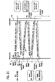
- Fig. 7 is a graphical representation having time on the vertical axis and distance along the network on the horizontal axis, showing transmission of configuration messages to the input circuit, the controller and the output circuit, forming the foundation of the safety protocol of the present invention
- Fig. 8 is a figure similar to that of Fig. 7 showing the transmission of messages after the configuration process during a start-up and run-time phase of the network;
- Fig. 9 is a block diagram of the industrial controller of Fig. 1 showing the division of communications between the input circuit, the controller and the output circuit into producer-consumer pairs such as provides redundant communication over a single network and the varied topologies of the implementations of Figs. 2, 3 and 4 ;
- Fig. 10 is a flow chart showing the principle stages of the safety protocol of initialization, start-up, and run-time;
- Fig. 11 is a figure similar to that of Fig. 7 showing normal protocol operation under the safety protocol of the present invention during run-time;
- Fig. 12 is a figure similar to Fig. 11 showing protocol operation with a corrupted producer message
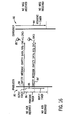
- Fig. 13 is a figure similar to Fig. 11 showing protocol operation with a lost producer message
- Fig. 14 is a figure similar to Fig. 11 showing protocol operation with a corrupted acknowledgement message from the consumer;
- Fig. 15 is a figure similar to Fig. 11 showing protocol operation with a lost consumer acknowledgement message
- Fig. 16 is a figure similar to Fig. 11 showing protocol operation with disruption of the connection between the producer and consumer;
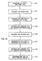
- Fig. 17 is a flow chart of a program executed by the producers of Fig. 9 in implementing the safety protocol
- Fig. 18 is a flow chart of a program executed by the consumers of Fig. 9 in implementing the safety protocol of the present invention.
- Fig. 19 is a flow chart of steps performed in accordance with an alternate embodiment of the invention.
- Fig. 20 is a schematic block diagram of a control system in accordance with the alternate embodiment described in Fig. 19 ;
- Fig. 21 is a fragmentary view similar to Fig. 20 , showing an alternative configuration of the input circuit of Fig. 20 using conventional control input circuits without redundant components;
- Fig. 22 is a fragmentary view similar to Fig. 20 , showing an alternative configuration of the output circuit of Fig. 20 using conventional control output circuits without redundant components;
- FIG. 23A-C are illustrations of data altering techniques performed in accordance with the alternate embodiment illustrated in Figs. 19-22 .
- the present invention can be part of a "safety system” used to protect human life and limb in the industrial environment. Nevertheless, the term “safety” as used herein is not a representation that the present invention will make an industrial process safe or that other systems will produce unsafe operation. Safety in an industrial process depends on a wide variety of factors outside of the scope of the present invention including: design of the safety system, installation and maintenance of the components of the safety system, and the cooperation and training of individuals using the safety system. Although the present invention is intended to be highly reliable, all physical systems are susceptible to failure and provision must be made for such failure.
- an industrial control system 10 for implementing a safety system includes a controller 12 communicating on a serial network 15 with remote input module 14 and remote output module 16.
- the network 15 may be a standard and commonly available high-speed serial network including but not limited to: Ethernet, DeviceNet, ControlNet, Firewire, FieldBus, or CAN protocol.
- the network 15 may optionally include a bridge 17 translating between different of the above standard or other protocols. As will be understood from the following, the present invention may be easily adapted to applications that use a bridge.
- Input module 14 may accept input signals 18 (on like-designated lines) which are communicated over the network 15 to the industrial controller 12.
- the signals 18 may be processed under a control program implementing a safety system (such as a machine lock-out or emergency stop) and further signals sent to the output module 16 which may produce output signals 20 (on like-designated lines) to an actuator 22.
- a safety system such as a machine lock-out or emergency stop
- the input signals 18 may come from a switch 19 which may be any of a variety of devices producing safety input signals including but not limited to emergency stop switches, interlock switches, light curtains and other proximity detectors.
- the actuator 22 may be a relay, solenoid, motor, enunciator, lamp or other device implementing a safety function.
- a standard computer which may be used as a configuration terminal 24 whose purposes will be described below.
- the switch 19 may produce redundant signals 18a and 18b where signal 18a is, for example, from a first contact within the switch 19, and signal 18b is from a second independent contact within switch 19.
- the contacts may have the same logic (as shown) both being normally open (e.g., closed with actuation of a pushbutton 26) or may be inverted logic with one contact normally open and one contact normally closed. In either case, redundant signals 18a and 18b are generated so as to provide for higher reliability in the determining the state of the switch 19.
- the input module 14 may include redundant interface circuitry 28a receiving signals 18a and interface circuitry 28b receiving signal 18b.
- interface circuitry 28a and 28b may each receive both signal 18a and 18b (for internal comparison) or may receive signals 18a and 18b from a single contact.
- the contacts, in generating signals 18a and 18b, may each be provided with a separate voltage from the input circuitry 28a and 28b or from a common voltage source (not shown).
- Other redundant variations on these wiring systems, known in the art, may also be used.
- Each of the interface circuitry 28a and 28b may in turn provide signals to associated microcontrollers 30a and 30b.
- Microcontrollers 30a and 30b provide a computer processor, memory and a stored program for executing safety protocol programs as will be described below.
- the safety protocol may be executed by safety protocol circuits 32 with which microcontrollers 30a and 30b communicate.
- the safety protocol circuits 28a and 28b may be application-specific integrated circuits (ASIC).
- ASIC application-specific integrated circuits
- the microcontrollers 30a and 30b may communicate with each other through an internal bus 34 to compare signals 18a and 18b as will be described.
- Microcontrollers 30a and 30b or safety protocol circuits 28a and 28b in turn connect to standard network protocol circuits 36a and 36b of a type well known in the art for handling the low level protocol of the standard network 15.
- the standard network protocol circuits 36a and 36b are implemented by an ASIC whose implementation represents considerable development time and which cannot be easily modified.
- the standard network protocol circuits 36a and 36b transmits signals from the input module 14 on the network 15 to be received at the controller 12 through a similar standard network protocol circuits 38a and 38b. These signals are processed by the standard network protocol circuit 38 and provided to redundant safety protocol circuits 40a and 40b, being similar to safety protocol circuits 32a and 32b described before. These safety protocol circuits 40a and 40b communicate with processors 42a and 42b, respectively, which include separate memory systems and control programs according to well-known redundancy techniques and which intercommunicate on internal bus 34'.
- Output signals generated by the processors 42a and 42b may be communicated back through the safety protocol circuits 40a and 40b to implement the safety protocol, as will be described below (or alternatively, the safety protocol may be handled by the processor 42a and 42b), and the output signals communicated to the standard network protocol circuits 38a and 38b for transmission again on network 15 to output module 16.
- Output module 16 may receive output data through a standard network protocol circuit 44 and 44' being similar to standard network protocol circuits 36a and 36b and 38a and 38b.
- the standard network protocol circuits 44 and 44' provide the data to safety protocol circuits 46a and 46b, which in turn provide them to redundant controllers 48a and 48b.
- the safety protocol may be handled by the controllers 48a and 48b instead.
- the controllers 48a and 48b communicate by internal bus 34" and in turn provide signals to output interface circuits 50a and 50b which provide the output signals 20a and 20b.
- the output signals may be connected to the actuator 22 so that outputs must be enabled for the actuator 22 to be powered.
- a default safety state is produced (of no power to the actuator 22) if there is an inconsistency between the signals received by processors 48a and 48b.
- a change in the wiring to parallel configurations could create a safety state where the actuator is actuated unless both signals received by processors 48a and 48b are not enabled.
- a safety state may be enforced by a safety state signal transmitted from the controller 12 or the input module 14 to the microcontrollers 48a and 48b of output module 16, the latter which may respond by producing outputs to output interface circuits 50a and 50b determined by stored values of desired safety states programmed through the configuration terminal 24 as will be described further below.
- a bridge circuit 17 per the present invention could use the basic structure shown in the input module 14 but replacing the interface circuitry 28a and 28b of input module 14 with network protocol circuits 38a and 38b and safety protocol circuits of 40a and 40b (where the network protocol circuits 38 and 36 are for different protocols, thereby allowing seamless transmission of safety data per the techniques described below).
- the pair of network protocol circuits may be replaced by a single hardware circuit that handles communication for both redundant messages of data. Diversity is achieved first by encoding, or altering, one of the messages of redundant data in a predetermined manner prior to transmission through the network protocol circuit. The encoded data is subsequently decoded after the data has passed through the network protocol circuit, and both messages are compared to ensure that no systemic, or "common mode" errors exist in the circuitry.
- a single message contains two logical messages that are processed by a single processor in accordance with the present invention, as will become more apparent from the description below.
- encoding is achieved by inverting each bit of data by a predetermined one of each pair of microprocessors 230a and 230b in modules 212, 214, and 216 such that one data message 231a comprises the data received by the input interface, while the other data message 231b comprises the inverse of that data.
- the encoded data is decoded by uninverting the data. The decoded data is then compared to the other logical message to ensure integrity, and then once again decoded prior to transmission to the subsequent module. All data transmitted in accordance with this embodiment may be forwarded in conformance with the safety protocol described throughout the present invention.
- redundant messages 218a and 218b are transmitted by switch 219, and are subsequently received by interface circuitry 228a and 228b, respectively, of the input module 214.
- the interface circuitry then transmit signals to the appropriate microprocessor 230a and 230b at step 300.
- a predetermined one of these microprocessors for example microprocessor 230b compares the data to that received by microprocessor 230a to ensure the accurate transfer, and then inverts its data at step 302 while the data received by microprocessor 230a remains unaltered.
- the data is then sent through the appropriate safety protocol circuit 232a and 232b, as described above, to execute the safety protocol.
- the reduced hardware embodiment further implements a single Controller Area Network (CAN) controller and associated transceiver, identified collectively at 236, that routes the data packets to the appropriate CAN 238 of controller 212.
- CAN 236 thus routes both messages of data to their proper destination on the network, and reduces the amount of circuitry necessary as compared to those systems that employ separate network hardware for each redundant message.
- the reduced hardware embodiment permits redundancy in the data transfer without the need to employ two separate network modules, as will now be described.
- CAN 236 transmits both messages to CAN 238 located in control module 212, which routes the inverted data packet to a predetermined one of processors 242, and routes the unaltered data packet to the other processor at step 304.
- the processor uninverts the data and compares the uninverted data with the data received by processor 242a at step 306. If the two messages match, processor 242b then reinverts the data at step 308, and processes and transmits the data via CAN 238 to the CAN 244 of output module 216. If an error exists in either of the CAN modules, the data will not match, and the processor may revert to a safety state, as described above. It should be appreciated that the data may further transmitted from control module 212 to output module 216 via bridge 217, which facilitates data transfer between networks operating different standards or protocols, as described above.
- CAN 244 then transmits messages to respective processors 248a and 248b via safety protocol circuits 246a and 246b at step 310.
- Processor 248b uninverts the inverted data and compares with the data received by processor 248a at step 312 to ensure the successful data transmission. If, at any point in the data transfer, an inconsistency exists between the uninverted data and the unaltered data, a default safety state is produced (of, for example, no power to the actuator 222).
- the control process may be shut down if an inconsistency in data is detected.
- the data is then sent over output interface circuits 250a and 250b at step 312, which provide the output signals 220a and 220b to actuator 222.
- the respective microprocessor could be configured to format the data to include safety protocol, as described in more detail below, thus dispensing with the safety protocol circuits and reducing the necessary hardware components of the control system.
- a single processor could perform the tasks of the pair of processors.
- a single processor receives a pair of logical messages, one of which is inverted. The processor then uninverts that data, and compares it to the unaltered data for error detection. The processor receives a single message that includes the two logical messages, thereby further simplifying the communications network.
- the "reduced hardware" embodiment includes a single processor processing a single message that contains the redundant data.
- Fig. 23A illustrates the above-described inversion process.
- two messages of data that are received from lines 218a and 218b.
- the data is transferred to modules 214, 212, and 216, the data of one of the messages (message 218b as illustrated) is inverted.
- each bit of data on the predetermined message including the header 62, data 52, safety error detection data 58, and footer 64, as will be described below with reference to Fig. 6 , are all inverted.
- the reduced hardware embodiment is usable along with a cyclic redundancy code to enable two levels of safety. While the data comprises eight bits in accordance with the illustrated embodiment, any number of bits may be used.
- the data comprises peer to peer data, in which each party has the same capabilities, and either party can initiate a communication session.
- the data may alternatively be altered by shifting the data a predetermined number of positions on one of the messages.
- decoding is achieved by shifting each bit of data one position to the right, with the last bit being wrapped around to the first bit.
- This data manipulation technique may be decoded by shifting each bit of data on message 218b to the left to verify the data with that on message a.
- Fig. 23C illustrates yet another data manipulation technique for 8 bits of data, in which the position of the first half (first 4 bits for an 8 bit word) of the data is translated to the position of the second half (last 4 bits), and vice versa. This process is also decoded when comparing the two messages to ensure the data integrity.
- the inversion process ensures that each bit of the manipulated data will be different than the corresponding bit of the unaltered data. As a result, the integrity of each bit of data may be verified.
- specialized redundant input module 14 illustrated in Fig. 2 may be replaced with two standard input modules 14a and 14b, input module 14a holding the equivalent of previously described interface circuitry 28a, microcontroller 30a, safety protocol circuit 32a and standard network protocol circuit 36a; and input module 14b holding the equivalent of interface circuitry 28b, microcontroller 30b, safety protocol circuit 32b, and standard network protocol circuit 36b.
- the operation of safety protocol circuits 32a and 32b are implemented in the firmware of the microcontrollers 30a and 30b and effected via messages communicated on the network 15 rather than the internal bus 34.
- the specialized redundant input module 214 illustrated in Fig. 20 may be replaced with two standard input modules 214a and 214b, input module 214a holding the equivalent of previously described interface circuitry 228a, microcontroller 230a, safety protocol circuit 232a and standard network protocol circuit 236a; and input module 214b holding the equivalent of interface circuitry 228b, microcontroller 230b, safety protocol circuit 232b, and standard network protocol circuit 236b.
- the operation of safety protocol circuits 232a and 232b are implemented in the firmware of the microcontrollers 230a and 230b and effected via messages communicated on the network 215 rather than the internal bus 234.
- output module 16 may be implemented by separate output circuits 16a and 16b, output module 16a including the equivalent of standard network protocol circuit 44, safety protocol circuit 46a, microcontroller 48a, and output interface circuit 50a, with output module 16b including the equivalents of standard network protocol circuit 44 as 44', safety protocol circuit 46b, microcontroller 48b, and output interface circuit 50b.
- output module 16a including the equivalent of standard network protocol circuit 44
- safety protocol circuit 46a safety protocol circuit 46a
- microcontroller 48a microcontroller 48a
- output interface circuit 50b the equivalents of standard network protocol circuit 44 as 44', safety protocol circuit 46b, microcontroller 48b, and output interface circuit 50b.
- the present invention provides a protocol that is indifferent to the exact parsing of the safety components among physical devices having addresses on the network 15.
- output module 216 may be implemented by separate output circuits 216a and 216b, output module 216a including the equivalent of standard network protocol circuit 244 as 244a, safety protocol circuit 246a, microcontroller 248a, and output interface circuit 250a.
- Output module 216b includes the equivalents of standard network protocol circuit 244 as 244b, safety protocol circuit 246b, microcontroller 248b, and output interface circuit 250b.
- the present invention provides a protocol that is indifferent to the exact parsing of the safety components among physical devices having addresses on the network 215.
- communication between modules 14a and 14b, and 214a and 214b is accomplished over links 43 and 243, respectively, that connect network protocol circuits 36a and 36b, and 236a and 236b, respectively.
- communication between modules 16a and 16b, and 216a and 216b is accomplished over links 43 and 243, respectively, that connect network protocol circuits 44 and 44', and 244a and 244b, respectively.
- the operation of the safety protocol circuits 32 and standard network protocol circuits 36 in the input circuit is to embed input data 52 from lines 18b within a safety-network protocol 54 implemented both as additional data attached to messages sent on network 15 and in the management of that data as will be described.
- the safety-network protocol 54 is in turn encapsulated in the standard network protocol 56 for seamless transmission on the network 15.
- the operation of the safety protocol circuits 32, 40 and 46 in conjunction with the standard network protocol circuits 36, 38 and 44 is to embed I/O data 52 (e.g., from lines 18b) within a safety-network protocol 54 implemented both as additional data attached to I/O data 52 sent on network 15 and in the management of the particulars of transmission of that I/O data 52.
- the safety-network protocol 54 is in turn encapsulated in the standard network protocol 56 for seamless transmission on the network 15.
- the data encapsulated in the safety-network protocol 54 and standard network protocol 56 can then be received (e.g., by the controller 12) and extracted through the successive operation of the standard network protocol circuits 36, 38 and 44 and the safety protocol circuits 32, 40 and 46 to provide the I/O data 32 in its basic state.
- Fig. 5 is only symbolic of the process and that the safety-network protocol 54 is not simply an encapsulation of the data 52 within for example safety data headers but rather the safety protocol includes timing constraints that may be executed in sequence with the standard network protocol 56 so that the safety-network protocol 54 may operate within the standard network protocol 56 without modification of the network 15 or standard network protocol circuits 36, 38 and 44.
- This dual level encapsulation and de-encapsulation is performed for each transmission of I/O data 52 on the network 15 that requires a high level of reliability commensurate with safety systems.
- the standard network protocol 56 may be used alone without the safety-network protocol 54 for communication with non-safety elements of the industrial control system 10. Because all data transmitted on the network 15 is embedded in the standard network protocol 56, the safety-network protocol 54 will work seamlessly with a variety of networks 15 providing they have data transmission capacity suitable for the I/O data 52 and sufficient in capacity to accept some added safety error detection data 58 of the safety-network protocol 54 as will be described.
- a first aspect of the safety-network protocol 54 is that the I/O data 52 is attached to safety error detection data 58 to form a safety message 60 that forms the data provided to the standard network protocol circuits 36, 38 and 44 to produce a network message 61.
- the safety error detection data 58 may include a sequence count indicating the local order in which the safety message 60 is transmitted with respect to earlier transmissions of safety messages. The sequence count is normally limited in range (0-3) as it is intended, as will be described, to detect the loss of only a single message.
- a cyclic redundancy code selected in the preferred embodiment to be twelve-bits.
- the cyclic redundancy code is functionally generated from the I/O data 52 and the sequence count so that an error in the transmission of either of those data elements can be detected when the CRC is recalculated by the receiving device and doesn't match.
- a twelve bit error code will allow the detection of errors with odd numbers of bit errors, all two-bit errors, all burst errors up to twelve bits and 99.951 % of burst errors larger than twelve bits, for up to two-thousand and forty seven bits of data of the safety message 60.
- the safety message 60 is embedded in the network headers and footers 62 and 64, which vary depending on the standard network protocol 56 of the network 15. Depending on the network 15, the network header and footer 62 and 64 may include a CRC code and sequence count and other similar safety error detection data 58 operating redundantly with the safety error detection data 58. Nevertheless, the safety message 60 includes its own safety error detection data 58 so as to be wholly network-independent to the degree possible.
- the safety-network protocol 54 also includes a configuration step that ensures proper communication under a connected messaging scheme.
- the communications between the controller 12, input module 14 (or input modules 14a and 14b) and the output module 16 (or output module 16a and 16b) may provide a connected messaging system.
- connected messaging involves opening a connection between pairs of logical devices one that acts as a "producers" of a message and one that acts as a "consumers" of the message.
- the process of opening the connection reserves bandwidth of the network and reserves necessary processing and buffering resources at the producer and consumer to ensure that data of the connection will be reliably transmitted and received.
- the connected messaging protocol may be implemented as part of the safety network protocol 54 or as part of the standard network protocol 56, the latter option limiting somewhat the types of standard networks 15 that may be used.
- Some standard network protocols that support connected messaging are DeviceNet and Control Net, Ethernet, and ATM.
- the input module 14 provides two producers 80 opening two connections with two consumers 82 of the controller 12, one for each of the signals 18a and 18b.
- these two connections mean that two separate network messages 61 will be sent over the network 15 thus decreasing the chance of loss of both messages.
- Fig. 3 For the implementation of Fig. 3 with separate input module 14a and 14b, two producers 80 are also provided. Even though the producers 80 are now in different devices (having different addresses on the network 15), the operation of the control program implementing the safety system, above the connection level, need not changed by these changes in implementations. Connected messaging thus makes the safety system largely indifferent to topologies as providing for a natural redundancy over a single network, or bridging or routing across multiple links
- Controller 12 likewise includes two producers 80 exchanging data with consumers 82 either in a single output module 16 per Fig. 2 or in separate output module 16a and 16b per the embodiment of Fig. 4 .
- Two arrows are shown between each producer 80 and consumer 82 indicating the paring of each message with an acknowledgment message under the safety protocol 54 as will be described below, per Fig. 9 .
- the bridge circuit 17, not shown in Fig. 9 would implement four consumers and four producers (two for each network side) as will be understood to those of ordinary skill in the art.
- the safety protocol more generally includes an initialization state, of which the first step is developing configuration data as indicated by process block 66.
- the configuration process involves developing configuration data at the configuration terminal 24 and ensuring that accurate copies of that configuration data are at each of the input module 14, the controller 12, and the output module 16.
- the configuration data is unique to each connection, provides essential components of the safety protocol, and identifies intercommunicating parties so as to reduce the possibility of improper connections injecting spurious data into the safety system. This is particularly important in allowing mixing of systems components observing the safety network protocol 54 with standard components observing only the standard network protocol. Devices may support multiple connections, in which case multiple configuration data specific to each connection will be used.
- the configuration data include data uniquely identifying the particular device of the input module 14, the controller 12, and the output module 16 holding the configuration data, and particularly the serial number of that device.
- the serial number is a unique and immutable part of the physical devices and thus together with an internal address of the logical devices within the physical device (which may establish independent connections) the serial number provides each connection with a unique identity eliminating the possibility of crossed connections between different devices once the configuration data is properly disseminated.
- the configuration data may also include a vendor identification number, a device code, a product code, major revision, minor revision, as well as network data including the logical, physical address of the device, all known in the art and identifying the particular device.
- the configuration data within a device may include the serial number of the device to which it is connected.
- connection data may also include data necessary for the implementation of the other aspects of the safety protocol as are yet to be described, including variables of "periodic time interval”, “reply timer interval”, “filter count”, and “retry limit”.
- the configuration data also includes the safety state to which the device will revert in the case of network error and a list of related I/O points indicating other I/O points (related to other connections), which should revert to the safety state if the present connection has an error. This later feature allows selective and intelligent disabling of the safety system upon a communication error as will be described.
- this data for example, data related to how particular devices should respond to a failure of any one device (e.g., the list of related I/O points, is dependant on the devices and their application and the system programmer must develop this data on an application specific basis.
- configuration data held within the configuration terminal 24 is sent to each of the input module 14, the controller 12, and the output module 16 as messages 66a, 66b and 66c.
- the configuration data will further indicate which controller in each module that is responsible for uninverting the data, and comparing the uninverted data to the unaltered data.
- the receiving input module 14, the controller 12, and the output module 16 store the configuration and respond with the same configuration message but changed to a one's complement form (being simply a different binary coding (the inversion)) of the configuration data received.
- This one's complement message is returned by messages 66d, 66e, and 66f from the respective input module 14, the controller 12, and the output module 16. If the configurations of messages 66a, 66b and 66c exactly match (after complementing) configuration data of messages 66d, 66e and 66f, the configuration was successful.
- the configuration data may be shown to a human operator for confirmation. If the operator finds that the configuration is correct, the configuration is applied as indicated by process 68 shown in Fig. 10 through messages 68a, 68b and 68c from the configuration terminal 24 to the respective input module 14, the controller 12, and the output module 16. The devices must acknowledge these messages via messages 68d, 68e and 68f within a predetermined time interval or the configuration will be cleared and no configuration will be considered to have occurred.
- the configuration data of messages 66 and 68 may be sent using only the standard network protocol 56.
- the safety protocol enters a start-up phase shown generally in Figs. 8 and 10 .
- the necessary safety connections are established and the configuration data is used to verify that the connections expected are those which are in fact made.
- the purpose of the start-up portion of the configuration is to prevent erroneous connections from being opened between: (1) devices in the safety system and other erroneous devices in the safety system, and (2) devices in the safety system and other devices not in the safety system in a mixed system.
- the connections are confirmed from the controller 12 to the input module 14 and the output module 16.
- the producers 80 in controller 12 send out open connection messages 70a and 70b to the input module 14 and the output module 16, respectively.
- the appropriate consumers 82 respond with connection acknowledgment message 70c and 70d, respectively.
- the producers 80 in controller 12 and input module 14 then send the configuration data to the consumer 82 in the controller 12 as indicated by messages 70e and 70f.
- the controller's consumers 82 check to see that the configuration data matches their configuration data and then send acknowledgment messages 70f and 70g acknowledging that match.
- conventional I/O data may then commence to be sent.
- the data 72a and 72b will be transmitted according to the portions of the safety protocol indicated by process blocks 72 involving formation of the safety message 60 incorporating safety error detection data 58 into the network message 61 as has been described above, and according to message handling protocols 74 operating independent of and in conjunction with the content of the safety message 60 which will now be discussed.
- the message handling protocols 74 provide for message time measurements and respond to errors in the safety error detection data 58 during run-time. These message-handling protocols 74 are implemented in the safety protocol circuits 32, 40 and 46 or may be implemented in software and are different for producers and consumers.
- the producer 80 upon run-time will send safety messages 84 (encapsulated in the standard network message 61 per safety message 60 as has been described above) to the consumer 82 per Fig. 11 .
- This sending is indicated generally in Fig. 17 .
- a periodic timer is started per process block 89 and a reply timer is started at the moment the message 84 is transmitted per process block 91.
- the periodic timer interval 86 is longer than the reply timer interval 88 as set in the configuration process described above.
- the consumer 82 prior to receiving the message 84 is continually checking to see if the periodic time interval 86' of its own periodic timer (started at the consumer's receipt of the last message 84) has expired as indicated in decision block 92.
- the periodic timer value 86' is generally greater than periodic timer value 86.
- timer value 86 has not expired, then at decision block 90, the consumer 82 checks to see if the message 84 has arrived. If no message 84 has arrived the program proceeds back to decision block 92 to again check if the periodic timer 86 has expired.
- the program proceeds to decision block 96 and checks to make sure that the sequence count is one greater than the sequence count of the last message received.
- the program proceeds to process block 94 and the periodic timer 86 is reset.
- the data is applied, for example, to an output or to update variables, and then at process block 98, an acknowledgment message 100 is returned to the producer 80.
- the producer 80 receiving the acknowledge message at decision block 102 proceeds to decision block 106 to determine if the periodic timer 86 has expired.
- the program proceeds to decision block 124 to check the CRC of the acknowledgement message 100.
- the cyclic redundancy code should match the data of the safety message 60 transmitted.
- the program proceeds to decision block 125 to determine whether the sequence count of the acknowledgment message 100 matches that of the message 84 that was sent.
- the data sent in message 84 is compared to the data of the acknowledgement message 100. If there is a match, then the program proceeds to decision block 129 where it loops until the periodic timer has expired, and then proceeds to process block 110 to prepare a new message 84.
- This process is repeated for multiple transmissions of safety messages 84 and acknowledgement messages 100.
- the safety message 84 is corrupted for example by electromagnetic interference 85.
- a message is received at the consumer 82, as indicated by Fig. 18 per process block 90, within the periodic timer value 86' as measured by process block 92 however there is an error in the CRC data as determined by decision block 112.
- the program proceeds to process block 114 and no action is taken and in particular no acknowledgement message 100 is returned.
- the program will proceed to decision block 118 to see if the shorter reply timer interval 88 has expired. If not, the program will loop back to process block 102. If so, the program will proceed to process block 120 to check if the retry limit has been exceeded. Initially this may not be the case and the program will proceed to process block 122 and a repeat message 84' having the same sequence count will be sent at process block 84, as also indicated by Fig. 12 . If the retry limit has been exceeded, the program proceeds to the safety state 126.
- This repeat message 84' will be received at the consumer 82 as indicated by process block 90 of Fig. 18 and assuming that it is correct it and that it has arrived within the periodic timer interval 86' based on the previous non-erroneous message, this message 84' results in the sending of an acknowledgment message 100 at process block 98 per the steps described above.
- the acknowledgment message 100 will occur within the periodic timer interval 86 of the producer and messages will be continued to be exchanged normally as has been previously described with respect to Fig. 11 .
- the safety message 84 arrived at the consumer 82 to be detected, albeit with errors. It is possible that the safety message 84 will not arrive at the consumer 82 either as a result of such extreme interference that it is not recognizable as a message under low level network protocols, or as a result of component failures between the producer and the consumer of an intermittent nature. Under this situation, the producer 80 sends the message 84 but the consumer does not receive a message at process block 90 of Fig. 18 .
- the producer 80 will produce a second message 84' which if received will result in an acknowledgment message 100 initiating a string of normal communications.
- the safety message 84 may successfully reach the consumer 82 with no errors but the acknowledgement message 100 may have errors introduced by electromagnetic interference 85.
- the producer 80 reacts as shown in Fig. 17 by decision block 106 to detect a receipt of an acknowledgment message 100 within the periodic timer interval 86. But there is an error in the data of the acknowledgment message 100.
- the program enters the safety state 126 in which outputs and inputs of the consumer 82 are set to a predefined safety state of the configuration data. Similarly, if the sequence count is correct but the acknowledgement data does not match per decision block 127, the program proceeds to the safety state 126. If the consumer 82 is the controller 12 messages may be sent to other I/O devices, indicated in the configuration data signaling them to move to the safety state as well.
- the program proceeds to decision block 118 to see if the reply timer has expired as described above.
- the reply timer expires the program proceeds to process block 120 as described above and checks the retry counter to see if the retry limit has been exceeded. If so, the program proceeds to the safety state 126 however often this will not have occurred and the program proceeds to process block 122 and a retry message 84' is prepared as indicated in Fig. 14 .
- a duplicate message 84 will be sent from the producer 80 however the sequence count will be identical to the sequence count of a message 84 previously received by the consumer 82.
- the CRC will be correct but as tested at subsequent decision block 96 the sequence code will be wrong.
- the program proceeds to process block 130 to check if the sequence code is one less than that expected. If not the program proceeds to the safety state 134. If so, however, the consumer 82 must conclude that the acknowledgment message 100 was lost and an acknowledgment of the previous message is sent again by the consumer at process block 132.
- the producer may be unable to connect with the consumer within the periodic interval 86' of the consumer. In that case the program proceeds to the safety state 134 directly from decision block 92 as shown in Fig. 18 .
Landscapes
- Engineering & Computer Science (AREA)
- Computer Networks & Wireless Communication (AREA)
- Signal Processing (AREA)
- Physics & Mathematics (AREA)
- General Physics & Mathematics (AREA)
- Automation & Control Theory (AREA)
- Safety Devices In Control Systems (AREA)
- Communication Control (AREA)
- Programmable Controllers (AREA)
- Selective Calling Equipment (AREA)
Claims (14)
- Système de communications (10) pour un automate industriel afin d'empêcher la propagation de données erronées en utilisant un réseau de communications série standard, le système de communications comprenant : des premier et second modules de communication (214, 216), en tant que partenaires de communication destinés à transmettre des données l'un à l'autre, dans lequel chaque partenaire possède les mêmes capacités, et l'un ou l'autre des partenaires est apte à ouvrir une session de communication, les modules de communication étant aptes à recevoir des données et à transmettre ces dernière dans des premier et second messages logiques redondants dans un message physique unique qui contient les deux messages logiques par l'intermédiaire du réseau de communications série standard, le premier message logique étant codé en utilisant une technique de manipulation de données réversible préalablement à la transmission afin qu'il diffère du second message logique de manière prédéterminée (218a ; 218b) ; les modules de communication étant en outre aptes à recevoir les premier et second messages logiques contenus dans le message physique unique en provenance de l'autre partenaire, décoder le premier message, et comparer les données du premier message décodé aux données du second message afin de déterminer si une erreur de transmission s'est produite.
- Système de communications selon la revendication 1, dans lequel les premier et second modules de communication comprennent en outre une paire de dispositifs à protocole indépendant des réseaux recevant respectivement les deux messages de données et produisant des données de sécurité formatées de haute fiabilité.
- Système de communications selon la revendication 2, dans lequel les dispositifs à protocole indépendant des réseaux formatent les données en ajoutant des données de détection d'erreur constituées par : un code de redondance cyclique associé aux données et un comptage de séquence associé à un ordre local de transmission des données par rapport à d'autres données transmises.
- Système de communications selon la revendication 1, comprenant en outre un dispositif à protocole de réseau standard fonctionnant sur les modules de communication et recevant les deux messages logiques et formatant en outre les données pour la transmission conformément à un protocole d'un réseau de communications série standard.
- Système de communications selon la revendication 4, dans lequel le premier message logique est codé en inversant chaque bit de données, et décodé en désinversant chaque bit de données inversé.
- Système de communications selon la revendication 1, dans lequel l'erreur de transmission est détectée si le message décodé n'est pas égal au second message, et
dans lequel un état de sécurité par défaut des données se produit lorsqu'une erreur de transmission est détectée. - Système de communications selon la revendication 1, dans lequel le réseau de communications est choisi dans le groupe de réseaux comprenant Ethernet, DeviceNet, ControlNet, Fire Wire, Field Bus, et le protocole CAN.
- Système de communications selon la revendication 1, dans lequel le premier module de communication comprend une paire de processeurs, dont l'un est dédié au traitement du premier message logique, et dont l'autre est dédié au traitement du second message logique,
ou
dans lequel le premier module de communication comprend un processeur unique dédié au traitement des premier et second messages logiques. - Système de communications selon la revendication 1, dans lequel le second module de communication comprend une paire de processeurs, dont l'un est dédié au traitement du premier message logique, et dont l'autre est dédié au traitement du second message logique,
ou
dans lequel le second module de communication comprend un processeur unique dédié au traitement des premier et second messages logiques. - Système de communications selon la revendication 1, dans lequel les données comprennent des données E/S, ou des données poste à poste.
- Procédé de transmission de données de commande sur un système de communications pour un automate industriel afin d'empêcher la propagation de données erronées en utilisant un réseau de communications série standard, le procédé comprenant les étapes consistant à :(a) recevoir (300) des données pour la commande d'un processus industriel sur un premier module de communication, celui-ci étant un partenaire de communication,(b) produire des premier et second messages logiques redondants, les deux messages comprenant des données reçues pour la transmission ;(c) coder (302) le premier message logique en utilisant une technique de manipulation de données réversible avant la transmission de manière à ce qu'il diffère du second message logique d'une manière prédéterminée ;(d) transmettre (304) les deux messages logiques depuis un circuit à protocole du premier module de communication à un circuit à protocole du second module de communication, dans un message physique unique qui contient les deux messages logiques par l'intermédiaire du réseau de communications standard ;(e) décoder (306) les données codées dans le second module de communication, qui est un second partenaire de communication ; et(f) après l'étape (e), comparer (306) le premier message logique décodé avec le second message logique afin de déterminer si une erreur de transmission s'est produite,
le procédé comprenant en outre une étape consistant à ouvrir une session de communication pour transmettre les données, et chaque partenaire possédant les mêmes capacités, et l'un ou l'autre des partenaires pouvant ouvrir la session de communication. - Procédé selon la revendication 11, comprenant en outre le formatage des données en ajoutant des données de détection d'erreurs sélectionnées dans le groupe constitué par : un code de redondance cyclique associé aux données et un comptage de séquence associé à un ordre local de transmission des données par rapport à d'autres données transmises.
- Procédé selon la revendication 11, dans lequel l'étape (c) est effectuée par un processeur unique,
ou
dans lequel les étapes (e) et (f) sont exécutées par un processeur unique. - Procédé selon la revendication 11, comprenant en outre le renvoi d'un message d'accusé de réception lors de la réception des données,
dans lequel le message d'accusé de réception comprend les données, et dans lequel une erreur est détectée en comparant les données de l'étape (d) aux données du message d'accusé de réception.
Applications Claiming Priority (2)
| Application Number | Priority Date | Filing Date | Title |
|---|---|---|---|
| US09/951,251 US6915444B2 (en) | 2001-09-12 | 2001-09-12 | Network independent safety protocol for industrial controller using data manipulation techniques |
| EP02759595A EP1506481B1 (fr) | 2001-09-12 | 2002-09-09 | Protocole de securite independant de reseau pour controleur industriel utilisant des techniques de manipulation de donnees |
Related Parent Applications (1)
| Application Number | Title | Priority Date | Filing Date |
|---|---|---|---|
| EP02759595.8 Division | 2002-09-09 |
Publications (3)
| Publication Number | Publication Date |
|---|---|
| EP2325749A2 EP2325749A2 (fr) | 2011-05-25 |
| EP2325749A3 EP2325749A3 (fr) | 2011-11-23 |
| EP2325749B1 true EP2325749B1 (fr) | 2013-03-27 |
Family
ID=25491485
Family Applications (2)
| Application Number | Title | Priority Date | Filing Date |
|---|---|---|---|
| EP10012930A Expired - Lifetime EP2325749B1 (fr) | 2001-09-12 | 2002-09-09 | Protocole de sécurité indépendant du réseau pour contrôleur industriel utilisant des techniques de manipulation de données |
| EP02759595A Expired - Lifetime EP1506481B1 (fr) | 2001-09-12 | 2002-09-09 | Protocole de securite independant de reseau pour controleur industriel utilisant des techniques de manipulation de donnees |
Family Applications After (1)
| Application Number | Title | Priority Date | Filing Date |
|---|---|---|---|
| EP02759595A Expired - Lifetime EP1506481B1 (fr) | 2001-09-12 | 2002-09-09 | Protocole de securite independant de reseau pour controleur industriel utilisant des techniques de manipulation de donnees |
Country Status (5)
| Country | Link |
|---|---|
| US (1) | US6915444B2 (fr) |
| EP (2) | EP2325749B1 (fr) |
| AT (1) | ATE522864T1 (fr) |
| AU (1) | AU2002324922A1 (fr) |
| WO (1) | WO2003023561A2 (fr) |
Families Citing this family (96)
| Publication number | Priority date | Publication date | Assignee | Title |
|---|---|---|---|---|
| US20030214953A1 (en) * | 2002-05-14 | 2003-11-20 | Ge Medical Systems Global Technology Company, Llc | Networked magnetic resonance imaging system and method incorporating same |
| US7105526B2 (en) | 2002-06-28 | 2006-09-12 | Banyu Pharmaceuticals Co., Ltd. | Benzimidazole derivatives |
| US7289861B2 (en) * | 2003-01-28 | 2007-10-30 | Fisher-Rosemount Systems, Inc. | Process control system with an embedded safety system |
| US7330768B2 (en) * | 2003-01-28 | 2008-02-12 | Fisher-Rosemount Systems, Inc. | Integrated configuration in a process plant having a process control system and a safety system |
| US7772188B2 (en) | 2003-01-28 | 2010-08-10 | Ironwood Pharmaceuticals, Inc. | Methods and compositions for the treatment of gastrointestinal disorders |
| US7865251B2 (en) * | 2003-01-28 | 2011-01-04 | Fisher-Rosemount Systems, Inc. | Method for intercontroller communications in a safety instrumented system or a process control system |
| DE10325263B4 (de) * | 2003-06-03 | 2013-09-19 | Phoenix Contact Gmbh & Co. Kg | Sicherstellung von maximalen Reaktionszeiten in komplexen oder verteilten sicheren und/oder nicht sicheren Systemen |
| KR100605216B1 (ko) * | 2003-05-30 | 2006-07-31 | 엘지전자 주식회사 | 네트워크 디바이스 |
| KR100638017B1 (ko) * | 2003-05-30 | 2006-10-23 | 엘지전자 주식회사 | 네트워크 디바이스 |
| KR100605218B1 (ko) | 2003-05-30 | 2006-07-31 | 엘지전자 주식회사 | 홈 네트워크 시스템 |
| KR100596755B1 (ko) | 2003-05-30 | 2006-07-04 | 엘지전자 주식회사 | 홈 네트워크 시스템 |
| WO2004107660A1 (fr) * | 2003-05-30 | 2004-12-09 | Lg Electronics, Inc. | Systeme de reseau a domicile |
| GB0312414D0 (en) * | 2003-05-30 | 2003-07-02 | Fortress Interlocks Ltd | Security or safety bus system |
| US7328370B2 (en) * | 2003-09-12 | 2008-02-05 | Rockwell Automation Technologies, Inc. | Safety controller with simplified interface |
| US7228390B2 (en) * | 2003-09-12 | 2007-06-05 | Rockwell Automation Technologies, Inc. | Safety controller with hardware memory lock |
| US7287184B2 (en) * | 2003-09-16 | 2007-10-23 | Rockwell Automation Technologies, Inc. | High speed synchronization in dual-processor safety controller |
| US7213168B2 (en) | 2003-09-16 | 2007-05-01 | Rockwell Automation Technologies, Inc. | Safety controller providing for execution of standard and safety control programs |
| AU2004274309B2 (en) | 2003-09-22 | 2010-04-08 | Msd K.K. | Novel piperidine derivative |
| US7027880B2 (en) * | 2003-09-30 | 2006-04-11 | Rockwell Automation Technologies, Inc. | Safety controller providing rapid recovery of safety program data |
| US7117048B2 (en) * | 2003-09-30 | 2006-10-03 | Rockwell Automation Technologies, Inc. | Safety controller with safety response time monitoring |
| US7203885B2 (en) * | 2003-09-30 | 2007-04-10 | Rockwell Automation Technologies, Inc. | Safety protocol for industrial controller |
| US7278066B2 (en) * | 2003-10-22 | 2007-10-02 | Honeywell International Inc | Automatic fieldbus device load-mode identification |
| US8180466B2 (en) * | 2003-11-21 | 2012-05-15 | Rosemount Inc. | Process device with supervisory overlayer |
| CN1312880C (zh) * | 2004-01-13 | 2007-04-25 | 重庆邮电学院 | 基于tcp/ip的工业控制网络的安全策略实现方法及系统 |
| US20080125403A1 (en) | 2004-04-02 | 2008-05-29 | Merck & Co., Inc. | Method of Treating Men with Metabolic and Anthropometric Disorders |
| DE102004018857A1 (de) | 2004-04-19 | 2005-11-10 | Elektro Beckhoff Gmbh Unternehmensbereich Industrie Elektronik | Sicherheitssteuerung |
| DE102004039932A1 (de) * | 2004-08-17 | 2006-03-09 | Phoenix Contact Gmbh & Co. Kg | Verfahren und Vorrichtung zur Busankopplung sicherheitsrelevanter Prozesse |
| US8291063B2 (en) | 2005-03-04 | 2012-10-16 | Netapp, Inc. | Method and apparatus for communicating between an agent and a remote management module in a processing system |
| US7487343B1 (en) | 2005-03-04 | 2009-02-03 | Netapp, Inc. | Method and apparatus for boot image selection and recovery via a remote management module |
| US7899680B2 (en) | 2005-03-04 | 2011-03-01 | Netapp, Inc. | Storage of administrative data on a remote management device |
| US7805629B2 (en) | 2005-03-04 | 2010-09-28 | Netapp, Inc. | Protecting data transactions on an integrated circuit bus |
| US8090810B1 (en) | 2005-03-04 | 2012-01-03 | Netapp, Inc. | Configuring a remote management module in a processing system |
| DE102005010820C5 (de) | 2005-03-07 | 2014-06-26 | Phoenix Contact Gmbh & Co. Kg | Kopplung von sicheren Feldbussystemen |
| US7634760B1 (en) | 2005-05-23 | 2009-12-15 | Netapp, Inc. | System and method for remote execution of a debugging utility using a remote management module |
| CA2609388C (fr) | 2005-05-30 | 2013-08-06 | Banyu Pharmaceutical Co., Ltd. | Nouveau derive de piperidine |
| CN100364305C (zh) * | 2005-06-03 | 2008-01-23 | 重庆邮电学院 | 工业控制网络的信息安全方法及安全功能块 |
| US8942834B2 (en) * | 2005-06-27 | 2015-01-27 | Rockwell Automation Technologies, Inc. | Method and apparatus for communicating transactions between an industrial controller and a programming interface |
| US7272681B2 (en) * | 2005-08-05 | 2007-09-18 | Raytheon Company | System having parallel data processors which generate redundant effector date to detect errors |
| JPWO2007018248A1 (ja) | 2005-08-10 | 2009-02-19 | 萬有製薬株式会社 | ピリドン化合物 |
| EP1921065B1 (fr) | 2005-08-24 | 2010-10-20 | Banyu Pharmaceutical Co., Ltd. | Dérivé phénylpyridone |
| WO2007029847A1 (fr) | 2005-09-07 | 2007-03-15 | Banyu Pharmaceutical Co., Ltd. | Dérivé de pyridone substitué aromatique bicylique |
| WO2007048027A2 (fr) | 2005-10-21 | 2007-04-26 | Novartis Ag | Combinaison de composes organiques |
| AU2006307046A1 (en) | 2005-10-27 | 2007-05-03 | Msd K.K. | Novel benzoxathiin derivative |
| US8158791B2 (en) | 2005-11-10 | 2012-04-17 | Msd K.K. | Aza-substituted spiro derivatives |
| US8676357B2 (en) * | 2005-12-20 | 2014-03-18 | Fieldbus Foundation | System and method for implementing an extended safety instrumented system |
| EP1985070B1 (fr) * | 2006-02-17 | 2010-09-29 | Phoenix Contact GmbH & Co. KG | Procede et dispositif pour le couplage de bus de processus relatifs a la sécurité |
| AU2007301126A1 (en) | 2006-09-28 | 2008-04-03 | Banyu Pharmaceutical Co., Ltd. | Diaryl ketimine derivative |
| DE102006054124B4 (de) * | 2006-11-15 | 2009-05-28 | Phoenix Contact Gmbh & Co. Kg | Verfahren und System zur sicheren Datenübertragung |
| US9889239B2 (en) | 2007-03-23 | 2018-02-13 | Allegiance Corporation | Fluid collection and disposal system and related methods |
| US8500706B2 (en) | 2007-03-23 | 2013-08-06 | Allegiance Corporation | Fluid collection and disposal system having interchangeable collection and other features and methods relating thereto |
| US8460256B2 (en) | 2009-07-15 | 2013-06-11 | Allegiance Corporation | Collapsible fluid collection and disposal system and related methods |
| CA2682727C (fr) | 2007-04-02 | 2016-03-22 | Banyu Pharmaceutical Co., Ltd. | Derive d'indoledione |
| DE102007048813B4 (de) * | 2007-04-13 | 2020-07-30 | Endress + Hauser Process Solutions Ag | Verfahren zum Bereitstellen einer zuverlässigen Statusinformation für Messwerte in Prozessautomatisierungsanwendungen |
| EP2527360B1 (fr) | 2007-06-04 | 2015-10-28 | Synergy Pharmaceuticals Inc. | Agonistes de guanylase cyclase utiles pour le traitement de troubles gastro-intestinaux, d'inflammation, de cancer et d'autres troubles |
| US8969514B2 (en) | 2007-06-04 | 2015-03-03 | Synergy Pharmaceuticals, Inc. | Agonists of guanylate cyclase useful for the treatment of hypercholesterolemia, atherosclerosis, coronary heart disease, gallstone, obesity and other cardiovascular diseases |
| DE502008002379D1 (de) * | 2008-03-03 | 2011-03-03 | Sick Ag | Sicherheitsvorrichtung zur sicheren Ansteuerung angeschlossener Aktoren |
| US20110015181A1 (en) | 2008-03-06 | 2011-01-20 | Makoto Ando | Alkylaminopyridine derivative |
| US7914821B2 (en) * | 2008-03-07 | 2011-03-29 | KO DA Pharmaceuticals Co., Ltd. | Pharmaceutical composition for prevention and/or treatment of bone loss |
| EP2272841A1 (fr) | 2008-03-28 | 2011-01-12 | Banyu Pharmaceutical Co., Ltd. | Dérivé de diarylméthylamide à activité antagoniste sur un récepteur d'hormone concentrant la mélanine |
| EP2810951B1 (fr) | 2008-06-04 | 2017-03-15 | Synergy Pharmaceuticals Inc. | Agonistes de guanylate cyclase utile dans le traitement de troubles gastro-intestinaux, d'une inflammation, d'un cancer et d'autres troubles |
| AU2009261248A1 (en) | 2008-06-19 | 2009-12-23 | Banyu Pharmaceutical Co., Ltd. | Spirodiamine-diarylketoxime derivative |
| EP3241839B1 (fr) | 2008-07-16 | 2019-09-04 | Bausch Health Ireland Limited | Agonistes de guanylate cyclase utiles pour le traitement de troubles gastro-intestinaux, inflammatoires, cancéreux et autres |
| WO2010013595A1 (fr) | 2008-07-30 | 2010-02-04 | 萬有製薬株式会社 | Dérivé de cycloalkylamine à noyaux fusionnés à (5 chaînons)-(5 chaînons) ou (5 chaînons)–(6 chaînons) |
| CN101667897A (zh) * | 2008-09-01 | 2010-03-10 | 华为技术有限公司 | 一种实现物理层重传的方法、装置及系统 |
| WO2010047982A1 (fr) | 2008-10-22 | 2010-04-29 | Merck Sharp & Dohme Corp. | Nouveaux dérivés de benzimidazole cycliques utiles comme agents anti-diabétiques |
| JP5557845B2 (ja) | 2008-10-31 | 2014-07-23 | メルク・シャープ・アンド・ドーム・コーポレーション | 糖尿病用剤として有用な新規環状ベンゾイミダゾール誘導体 |
| JP5482275B2 (ja) * | 2009-04-01 | 2014-05-07 | セイコーエプソン株式会社 | 記憶装置、基板、液体容器、データ記憶部に書き込むべきデータをホスト回路から受け付ける方法、ホスト回路に対し電気的に接続可能な記憶装置を含むシステム |
| DE102009033529A1 (de) * | 2009-07-10 | 2011-01-13 | Pilz Gmbh & Co. Kg | Vorrichtung und Verfahren zum Steuern einer automatisierten Anlage, insbesondere eine Eisenbahnanlage |
| DE102009042354C5 (de) * | 2009-09-23 | 2017-07-13 | Phoenix Contact Gmbh & Co. Kg | Verfahren und Vorrichtung zur sicherheitsgerichteten Kommunikation im Kommunikations-Netzwerk einer Automatisierungs-Anlage |
| US8895596B2 (en) | 2010-02-25 | 2014-11-25 | Merck Sharp & Dohme Corp | Cyclic benzimidazole derivatives useful as anti-diabetic agents |
| EP2416516A1 (fr) * | 2010-08-04 | 2012-02-08 | BAE Systems PLC | Système de transmission de données à haute intégrité |
| ES2705691T3 (es) | 2010-08-04 | 2019-03-26 | Bae Systems Plc | Sistema de transmisión de datos de alta integridad |
| US9616097B2 (en) | 2010-09-15 | 2017-04-11 | Synergy Pharmaceuticals, Inc. | Formulations of guanylate cyclase C agonists and methods of use |
| BR112013021236B1 (pt) | 2011-02-25 | 2021-05-25 | Merck Sharp & Dohme Corp | composto derivado de benzimidazol, e, composição |
| US8643225B2 (en) | 2011-03-14 | 2014-02-04 | Rockwell Automation Technologies, Inc. | Lock-out, tag-out system using safety network |
| US8688247B2 (en) | 2011-04-06 | 2014-04-01 | Rockwell Automation Technologies, Inc. | Lock-out, tag-out system using safety programmable logic controller |
| US9071549B2 (en) | 2011-04-22 | 2015-06-30 | Mitsubishi Electric Corporation | Communication device using plurality of communication paths |
| DE102011084364A1 (de) | 2011-10-12 | 2013-04-18 | Endress + Hauser Wetzer Gmbh + Co Kg | Verfahren zur telegrammweisen Datenübertragung |
| US9527875B2 (en) | 2012-08-02 | 2016-12-27 | Merck Sharp & Dohme Corp. | Antidiabetic tricyclic compounds |
| RU2015140066A (ru) | 2013-02-22 | 2017-03-30 | Мерк Шарп И Доум Корп. | Противодиабетические бициклические соединения |
| WO2014139388A1 (fr) | 2013-03-14 | 2014-09-18 | Merck Sharp & Dohme Corp. | Nouveaux dérivés d'indole utiles en tant qu'agents antidiabétiques |
| CA2905435A1 (fr) | 2013-03-15 | 2014-09-25 | Synergy Pharmaceuticals Inc. | Compositions utiles pour le traitement de troubles gastro-intestinaux |
| CA2905438A1 (fr) | 2013-03-15 | 2014-09-25 | Synergy Pharmaceuticals Inc. | Agonistes de la guanylate cyclase et leurs utilisations |
| SI3004138T1 (sl) | 2013-06-05 | 2024-07-31 | Bausch Health Ireland Limited | Ultra čisti agonisti gvanilat ciklaze C, postopek za njihovo pripravo in uporabo |
| WO2015051496A1 (fr) | 2013-10-08 | 2015-04-16 | Merck Sharp & Dohme Corp. | Composés tricycliques antidiabétiques |
| US9298529B2 (en) | 2014-05-29 | 2016-03-29 | Freescale Semiconductor, Inc. | Indicating internal transmitter errors in a controller area network (CAN) |
| KR102431436B1 (ko) | 2014-08-29 | 2022-08-10 | 테스 파마 에스.알.엘. | α-아미노-β-카복시뮤콘산 세미알데히드 데카복실라제의 억제제 |
| DE102014217973A1 (de) * | 2014-09-09 | 2016-03-10 | Siemens Aktiengesellschaft | Verfahren und System zur gesicherten Kommunikation |
| KR20180073677A (ko) | 2015-11-13 | 2018-07-02 | 샌델 에이비아닉스 인코포레이티드 | 항공 전자 시스템, 아키텍처 및 방법 |
| AR109950A1 (es) | 2016-10-14 | 2019-02-06 | Tes Pharma S R L | INHIBIDORES DE LA ÁCIDO a-AMINO-b-CARBOXIMUCÓNICO SEMIALDEHÍDO DESCARBOXILASA |
| US11072602B2 (en) | 2016-12-06 | 2021-07-27 | Merck Sharp & Dohme Corp. | Antidiabetic heterocyclic compounds |
| WO2018118670A1 (fr) | 2016-12-20 | 2018-06-28 | Merck Sharp & Dohme Corp. | Composés de spirochromane antidiabétiques |
| US11029660B2 (en) * | 2017-05-15 | 2021-06-08 | Rockwell Automation Asia Pacific Business Center, Pte. Ltd. | Safety input system for monitoring a sensor in an industrial automation system |
| AR117122A1 (es) | 2018-11-20 | 2021-07-14 | Tes Pharma S R L | INHIBIDORES DE LA ÁCIDO a-AMINO-b-CARBOXIMUCÓNICO SEMIALDEHÍDO DESCARBOXILASA |
| US11424865B2 (en) | 2020-12-10 | 2022-08-23 | Fisher-Rosemount Systems, Inc. | Variable-level integrity checks for communications in process control environments |
| DE102025110478A1 (de) * | 2024-04-15 | 2025-10-16 | Sew-Eurodrive Gmbh & Co Kg | Antriebssystem, umfassend eine erste Komponente, eine zweite Komponente und eine Kommunikationsstrecke sowie Verfahren zum Betreiben eines solchen Antriebssystems |
Family Cites Families (17)
| Publication number | Priority date | Publication date | Assignee | Title |
|---|---|---|---|---|
| JPS58181393A (ja) * | 1982-04-16 | 1983-10-24 | Meidensha Electric Mfg Co Ltd | 符号伝送方法 |
| DE3702527A1 (de) * | 1987-01-28 | 1988-08-11 | Siemens Ag | Datenuebertragungseinrichtung mit wiederholung zu uebertragender datentelegramme |
| US5245616A (en) * | 1989-02-24 | 1993-09-14 | Rosemount Inc. | Technique for acknowledging packets |
| US5142538A (en) * | 1990-04-19 | 1992-08-25 | Photonics Corporation | Link protocol for rs 232 communications |
| JP3351175B2 (ja) * | 1995-06-15 | 2002-11-25 | 三菱電機株式会社 | 通信制御方法および装置 |
| NL9401142A (nl) * | 1994-07-11 | 1996-02-01 | Nederland Ptt | Overdracht van berichten via verschillende subnetwerken. |
| US5642354A (en) * | 1995-09-01 | 1997-06-24 | Motorola, Inc. | Enhanced access burst in a wireless communication system |
| WO1997011565A2 (fr) | 1995-09-21 | 1997-03-27 | Motorola Inc. | Protocole integre |
| JP3167336B2 (ja) * | 1996-03-08 | 2001-05-21 | シーメンス アクチエンゲゼルシャフト | 自動車における乗員保護手段の制御のための装置 |
| US5920581A (en) * | 1996-05-31 | 1999-07-06 | Vtech Communications, Ltd. | Error detection method and apparatus for digital communication data packets |
| US6044480A (en) | 1996-12-06 | 2000-03-28 | Ncr Corporation | Message generation and verification for a communication network |
| JPH10198539A (ja) * | 1997-01-08 | 1998-07-31 | Fuji Xerox Co Ltd | 画像形成装置および画像形成方法 |
| US6560202B1 (en) | 1998-07-27 | 2003-05-06 | Lucent Technologies Inc. | Control architecture using a multi-layer embedded signal status protocol |
| US5918022A (en) * | 1998-09-28 | 1999-06-29 | Cisco Technology, Inc. | Protocol for transporting reservation system data over a TCP/IP network |
| DE19857154C1 (de) * | 1998-12-11 | 2000-03-16 | Daimler Chrysler Ag | Verfahren zur Datenübertragung |
| US6601210B1 (en) * | 1999-09-08 | 2003-07-29 | Mellanox Technologies, Ltd | Data integrity verification in a switching network |
| US6721900B1 (en) * | 1999-12-22 | 2004-04-13 | Rockwell Automation Technologies, Inc. | Safety network for industrial controller having reduced bandwidth requirements |
-
2001
- 2001-09-12 US US09/951,251 patent/US6915444B2/en not_active Expired - Lifetime
-
2002
- 2002-09-09 WO PCT/US2002/028601 patent/WO2003023561A2/fr not_active Ceased
- 2002-09-09 EP EP10012930A patent/EP2325749B1/fr not_active Expired - Lifetime
- 2002-09-09 EP EP02759595A patent/EP1506481B1/fr not_active Expired - Lifetime
- 2002-09-09 AU AU2002324922A patent/AU2002324922A1/en not_active Abandoned
- 2002-09-09 AT AT02759595T patent/ATE522864T1/de not_active IP Right Cessation
Also Published As
| Publication number | Publication date |
|---|---|
| EP2325749A2 (fr) | 2011-05-25 |
| US6915444B2 (en) | 2005-07-05 |
| US20030051203A1 (en) | 2003-03-13 |
| WO2003023561A2 (fr) | 2003-03-20 |
| EP1506481B1 (fr) | 2011-08-31 |
| EP1506481A2 (fr) | 2005-02-16 |
| EP2325749A3 (fr) | 2011-11-23 |
| ATE522864T1 (de) | 2011-09-15 |
| WO2003023561A3 (fr) | 2004-12-09 |
| EP1506481A4 (fr) | 2007-12-26 |
| AU2002324922A1 (en) | 2003-03-24 |
Similar Documents
| Publication | Publication Date | Title |
|---|---|---|
| EP2325749B1 (fr) | Protocole de sécurité indépendant du réseau pour contrôleur industriel utilisant des techniques de manipulation de données | |
| EP1425676B1 (fr) | Pont pour systeme de commande industriel utilisant des techniques de manipulation de donnees | |
| US6631476B1 (en) | Safety network for industrial controller providing redundant connections on single media | |
| US6891850B1 (en) | Network independent safety protocol for industrial controller | |
| EP1240561B1 (fr) | Reseau de securite pour un controleur industriel ayant des imperatifs de largeur de bande reduits | |
| US6909923B2 (en) | Safety communication on a single backplane | |
| US6701198B1 (en) | Safety network for industrial controller allowing initialization on standard networks | |
| US7032045B2 (en) | Multi-protocol bus device | |
| US7076715B2 (en) | Safety network using phantom address information | |
| EP1521385A2 (fr) | Protocole de sécurité pour contrôleur industriel | |
| US7366774B2 (en) | Network delay monitor for safety control networks | |
| JPWO2003001307A1 (ja) | 安全ネットワークシステム及び安全スレーブ並びに通信方法 | |
| US7707319B2 (en) | Noninvasive testing of network interface error codes for safety network | |
| CN100480913C (zh) | 以安全为导向的控制系统 | |
| PT1789857E (pt) | Processo de transmissão de dados e sistema de automação para utilização de um tal processo de transmissão de dados | |
| CN100498607C (zh) | 数据传输方法及使用此种数据传输方法的自动化系统 | |
| US20050149631A1 (en) | Safety Modbus Protocol | |
| Schiffer et al. | Introduction to DeviceNet safety |
Legal Events
| Date | Code | Title | Description |
|---|---|---|---|
| PUAI | Public reference made under article 153(3) epc to a published international application that has entered the european phase |
Free format text: ORIGINAL CODE: 0009012 |
|
| AC | Divisional application: reference to earlier application |
Ref document number: 1506481 Country of ref document: EP Kind code of ref document: P |
|
| AK | Designated contracting states |
Kind code of ref document: A2 Designated state(s): AT BE BG CH CY CZ DE DK EE ES FI FR GB GR IE IT LI LU MC NL PT SE SK TR |
|
| PUAL | Search report despatched |
Free format text: ORIGINAL CODE: 0009013 |
|
| RIC1 | Information provided on ipc code assigned before grant |
Ipc: H04L 1/14 20060101ALI20111013BHEP Ipc: G06F 11/00 20060101AFI20111013BHEP Ipc: H04L 1/18 20060101ALI20111013BHEP |
|
| AK | Designated contracting states |
Kind code of ref document: A3 Designated state(s): AT BE BG CH CY CZ DE DK EE ES FI FR GB GR IE IT LI LU MC NL PT SE SK TR |
|
| 17P | Request for examination filed |
Effective date: 20120523 |
|
| GRAP | Despatch of communication of intention to grant a patent |
Free format text: ORIGINAL CODE: EPIDOSNIGR1 |
|
| RIC1 | Information provided on ipc code assigned before grant |
Ipc: G06F 11/00 20060101AFI20120926BHEP Ipc: H04L 1/18 20060101ALI20120926BHEP Ipc: H04L 1/08 20060101ALI20120926BHEP Ipc: H04L 1/22 20060101ALI20120926BHEP Ipc: H04L 1/14 20060101ALI20120926BHEP |
|
| GRAS | Grant fee paid |
Free format text: ORIGINAL CODE: EPIDOSNIGR3 |
|
| GRAA | (expected) grant |
Free format text: ORIGINAL CODE: 0009210 |
|
| AC | Divisional application: reference to earlier application |
Ref document number: 1506481 Country of ref document: EP Kind code of ref document: P |
|
| AK | Designated contracting states |
Kind code of ref document: B1 Designated state(s): AT BE BG CH CY CZ DE DK EE ES FI FR GB GR IE IT LI LU MC NL PT SE SK TR |
|
| REG | Reference to a national code |
Ref country code: GB Ref legal event code: FG4D |
|
| REG | Reference to a national code |
Ref country code: CH Ref legal event code: EP |
|
| REG | Reference to a national code |
Ref country code: AT Ref legal event code: REF Ref document number: 603783 Country of ref document: AT Kind code of ref document: T Effective date: 20130415 |
|
| REG | Reference to a national code |
Ref country code: IE Ref legal event code: FG4D |
|
| REG | Reference to a national code |
Ref country code: DE Ref legal event code: R096 Ref document number: 60244726 Country of ref document: DE Effective date: 20130523 |
|
| PG25 | Lapsed in a contracting state [announced via postgrant information from national office to epo] |
Ref country code: SE Free format text: LAPSE BECAUSE OF FAILURE TO SUBMIT A TRANSLATION OF THE DESCRIPTION OR TO PAY THE FEE WITHIN THE PRESCRIBED TIME-LIMIT Effective date: 20130327 Ref country code: BG Free format text: LAPSE BECAUSE OF FAILURE TO SUBMIT A TRANSLATION OF THE DESCRIPTION OR TO PAY THE FEE WITHIN THE PRESCRIBED TIME-LIMIT Effective date: 20130627 |
|
| REG | Reference to a national code |
Ref country code: AT Ref legal event code: MK05 Ref document number: 603783 Country of ref document: AT Kind code of ref document: T Effective date: 20130327 |
|
| PG25 | Lapsed in a contracting state [announced via postgrant information from national office to epo] |
Ref country code: GR Free format text: LAPSE BECAUSE OF FAILURE TO SUBMIT A TRANSLATION OF THE DESCRIPTION OR TO PAY THE FEE WITHIN THE PRESCRIBED TIME-LIMIT Effective date: 20130628 Ref country code: FI Free format text: LAPSE BECAUSE OF FAILURE TO SUBMIT A TRANSLATION OF THE DESCRIPTION OR TO PAY THE FEE WITHIN THE PRESCRIBED TIME-LIMIT Effective date: 20130327 |
|
| REG | Reference to a national code |
Ref country code: NL Ref legal event code: VDEP Effective date: 20130327 |
|
| PG25 | Lapsed in a contracting state [announced via postgrant information from national office to epo] |
Ref country code: BE Free format text: LAPSE BECAUSE OF FAILURE TO SUBMIT A TRANSLATION OF THE DESCRIPTION OR TO PAY THE FEE WITHIN THE PRESCRIBED TIME-LIMIT Effective date: 20130327 |
|
| PG25 | Lapsed in a contracting state [announced via postgrant information from national office to epo] |
Ref country code: EE Free format text: LAPSE BECAUSE OF FAILURE TO SUBMIT A TRANSLATION OF THE DESCRIPTION OR TO PAY THE FEE WITHIN THE PRESCRIBED TIME-LIMIT Effective date: 20130327 Ref country code: SK Free format text: LAPSE BECAUSE OF FAILURE TO SUBMIT A TRANSLATION OF THE DESCRIPTION OR TO PAY THE FEE WITHIN THE PRESCRIBED TIME-LIMIT Effective date: 20130327 Ref country code: PT Free format text: LAPSE BECAUSE OF FAILURE TO SUBMIT A TRANSLATION OF THE DESCRIPTION OR TO PAY THE FEE WITHIN THE PRESCRIBED TIME-LIMIT Effective date: 20130729 Ref country code: NL Free format text: LAPSE BECAUSE OF FAILURE TO SUBMIT A TRANSLATION OF THE DESCRIPTION OR TO PAY THE FEE WITHIN THE PRESCRIBED TIME-LIMIT Effective date: 20130327 Ref country code: AT Free format text: LAPSE BECAUSE OF FAILURE TO SUBMIT A TRANSLATION OF THE DESCRIPTION OR TO PAY THE FEE WITHIN THE PRESCRIBED TIME-LIMIT Effective date: 20130327 Ref country code: CZ Free format text: LAPSE BECAUSE OF FAILURE TO SUBMIT A TRANSLATION OF THE DESCRIPTION OR TO PAY THE FEE WITHIN THE PRESCRIBED TIME-LIMIT Effective date: 20130327 Ref country code: ES Free format text: LAPSE BECAUSE OF FAILURE TO SUBMIT A TRANSLATION OF THE DESCRIPTION OR TO PAY THE FEE WITHIN THE PRESCRIBED TIME-LIMIT Effective date: 20130708 |
|
| PG25 | Lapsed in a contracting state [announced via postgrant information from national office to epo] |
Ref country code: CY Free format text: LAPSE BECAUSE OF FAILURE TO SUBMIT A TRANSLATION OF THE DESCRIPTION OR TO PAY THE FEE WITHIN THE PRESCRIBED TIME-LIMIT Effective date: 20130327 |
|
| PG25 | Lapsed in a contracting state [announced via postgrant information from national office to epo] |
Ref country code: DK Free format text: LAPSE BECAUSE OF FAILURE TO SUBMIT A TRANSLATION OF THE DESCRIPTION OR TO PAY THE FEE WITHIN THE PRESCRIBED TIME-LIMIT Effective date: 20130327 |
|
| PLBE | No opposition filed within time limit |
Free format text: ORIGINAL CODE: 0009261 |
|
| STAA | Information on the status of an ep patent application or granted ep patent |
Free format text: STATUS: NO OPPOSITION FILED WITHIN TIME LIMIT |
|
| PG25 | Lapsed in a contracting state [announced via postgrant information from national office to epo] |
Ref country code: IT Free format text: LAPSE BECAUSE OF FAILURE TO SUBMIT A TRANSLATION OF THE DESCRIPTION OR TO PAY THE FEE WITHIN THE PRESCRIBED TIME-LIMIT Effective date: 20130327 |
|
| 26N | No opposition filed |
Effective date: 20140103 |
|
| REG | Reference to a national code |
Ref country code: DE Ref legal event code: R097 Ref document number: 60244726 Country of ref document: DE Effective date: 20140103 |
|
| PG25 | Lapsed in a contracting state [announced via postgrant information from national office to epo] |
Ref country code: MC Free format text: LAPSE BECAUSE OF FAILURE TO SUBMIT A TRANSLATION OF THE DESCRIPTION OR TO PAY THE FEE WITHIN THE PRESCRIBED TIME-LIMIT Effective date: 20130327 |
|
| REG | Reference to a national code |
Ref country code: CH Ref legal event code: PL |
|
| REG | Reference to a national code |
Ref country code: IE Ref legal event code: MM4A |
|
| PG25 | Lapsed in a contracting state [announced via postgrant information from national office to epo] |
Ref country code: CH Free format text: LAPSE BECAUSE OF NON-PAYMENT OF DUE FEES Effective date: 20130930 Ref country code: IE Free format text: LAPSE BECAUSE OF NON-PAYMENT OF DUE FEES Effective date: 20130909 Ref country code: LI Free format text: LAPSE BECAUSE OF NON-PAYMENT OF DUE FEES Effective date: 20130930 |
|
| PG25 | Lapsed in a contracting state [announced via postgrant information from national office to epo] |
Ref country code: TR Free format text: LAPSE BECAUSE OF FAILURE TO SUBMIT A TRANSLATION OF THE DESCRIPTION OR TO PAY THE FEE WITHIN THE PRESCRIBED TIME-LIMIT Effective date: 20130327 |
|
| PG25 | Lapsed in a contracting state [announced via postgrant information from national office to epo] |
Ref country code: LU Free format text: LAPSE BECAUSE OF NON-PAYMENT OF DUE FEES Effective date: 20130909 |
|
| REG | Reference to a national code |
Ref country code: FR Ref legal event code: PLFP Year of fee payment: 14 |
|
| REG | Reference to a national code |
Ref country code: FR Ref legal event code: PLFP Year of fee payment: 15 |
|
| REG | Reference to a national code |
Ref country code: FR Ref legal event code: PLFP Year of fee payment: 16 |
|
| REG | Reference to a national code |
Ref country code: FR Ref legal event code: PLFP Year of fee payment: 17 |
|
| PGFP | Annual fee paid to national office [announced via postgrant information from national office to epo] |
Ref country code: FR Payment date: 20200819 Year of fee payment: 19 Ref country code: GB Payment date: 20200819 Year of fee payment: 19 Ref country code: DE Payment date: 20200819 Year of fee payment: 19 |
|
| REG | Reference to a national code |
Ref country code: DE Ref legal event code: R119 Ref document number: 60244726 Country of ref document: DE |
|
| GBPC | Gb: european patent ceased through non-payment of renewal fee |
Effective date: 20210909 |
|
| PG25 | Lapsed in a contracting state [announced via postgrant information from national office to epo] |
Ref country code: GB Free format text: LAPSE BECAUSE OF NON-PAYMENT OF DUE FEES Effective date: 20210909 Ref country code: FR Free format text: LAPSE BECAUSE OF NON-PAYMENT OF DUE FEES Effective date: 20210930 Ref country code: DE Free format text: LAPSE BECAUSE OF NON-PAYMENT OF DUE FEES Effective date: 20220401 |