EP1521401B1 - Système de l'industrie des systèmes batiments et procédée pour la configuration dudit système - Google Patents
Système de l'industrie des systèmes batiments et procédée pour la configuration dudit système Download PDFInfo
- Publication number
- EP1521401B1 EP1521401B1 EP04022509.6A EP04022509A EP1521401B1 EP 1521401 B1 EP1521401 B1 EP 1521401B1 EP 04022509 A EP04022509 A EP 04022509A EP 1521401 B1 EP1521401 B1 EP 1521401B1
- Authority
- EP
- European Patent Office
- Prior art keywords
- devices
- configurator
- controller
- subnetwork
- subnetworks
- Prior art date
- Legal status (The legal status is an assumption and is not a legal conclusion. Google has not performed a legal analysis and makes no representation as to the accuracy of the status listed.)
- Expired - Lifetime
Links
Images

Classifications
-
- H—ELECTRICITY
- H04—ELECTRIC COMMUNICATION TECHNIQUE
- H04L—TRANSMISSION OF DIGITAL INFORMATION, e.g. TELEGRAPHIC COMMUNICATION
- H04L12/00—Data switching networks
- H04L12/28—Data switching networks characterised by path configuration, e.g. LAN [Local Area Networks] or WAN [Wide Area Networks]
- H04L12/2803—Home automation networks
-
- H—ELECTRICITY
- H05—ELECTRIC TECHNIQUES NOT OTHERWISE PROVIDED FOR
- H05B—ELECTRIC HEATING; ELECTRIC LIGHT SOURCES NOT OTHERWISE PROVIDED FOR; CIRCUIT ARRANGEMENTS FOR ELECTRIC LIGHT SOURCES, IN GENERAL
- H05B47/00—Circuit arrangements for operating light sources in general, i.e. where the type of light source is not relevant
- H05B47/10—Controlling the light source
- H05B47/175—Controlling the light source by remote control
- H05B47/18—Controlling the light source by remote control via data-bus transmission
-
- H—ELECTRICITY
- H04—ELECTRIC COMMUNICATION TECHNIQUE
- H04L—TRANSMISSION OF DIGITAL INFORMATION, e.g. TELEGRAPHIC COMMUNICATION
- H04L12/00—Data switching networks
- H04L12/28—Data switching networks characterised by path configuration, e.g. LAN [Local Area Networks] or WAN [Wide Area Networks]
- H04L12/2803—Home automation networks
- H04L12/283—Processing of data at an internetworking point of a home automation network
-
- H—ELECTRICITY
- H04—ELECTRIC COMMUNICATION TECHNIQUE
- H04L—TRANSMISSION OF DIGITAL INFORMATION, e.g. TELEGRAPHIC COMMUNICATION
- H04L12/00—Data switching networks
- H04L12/28—Data switching networks characterised by path configuration, e.g. LAN [Local Area Networks] or WAN [Wide Area Networks]
- H04L12/44—Star or tree networks
-
- H—ELECTRICITY
- H04—ELECTRIC COMMUNICATION TECHNIQUE
- H04L—TRANSMISSION OF DIGITAL INFORMATION, e.g. TELEGRAPHIC COMMUNICATION
- H04L12/00—Data switching networks
- H04L12/28—Data switching networks characterised by path configuration, e.g. LAN [Local Area Networks] or WAN [Wide Area Networks]
- H04L12/46—Interconnection of networks
- H04L12/4604—LAN interconnection over a backbone network, e.g. Internet, Frame Relay
-
- H—ELECTRICITY
- H04—ELECTRIC COMMUNICATION TECHNIQUE
- H04L—TRANSMISSION OF DIGITAL INFORMATION, e.g. TELEGRAPHIC COMMUNICATION
- H04L41/00—Arrangements for maintenance, administration or management of data switching networks, e.g. of packet switching networks
- H04L41/08—Configuration management of networks or network elements
- H04L41/0803—Configuration setting
-
- H—ELECTRICITY
- H04—ELECTRIC COMMUNICATION TECHNIQUE
- H04L—TRANSMISSION OF DIGITAL INFORMATION, e.g. TELEGRAPHIC COMMUNICATION
- H04L41/00—Arrangements for maintenance, administration or management of data switching networks, e.g. of packet switching networks
- H04L41/08—Configuration management of networks or network elements
- H04L41/0803—Configuration setting
- H04L41/0806—Configuration setting for initial configuration or provisioning, e.g. plug-and-play
-
- H—ELECTRICITY
- H04—ELECTRIC COMMUNICATION TECHNIQUE
- H04L—TRANSMISSION OF DIGITAL INFORMATION, e.g. TELEGRAPHIC COMMUNICATION
- H04L61/00—Network arrangements, protocols or services for addressing or naming
- H04L61/50—Address allocation
- H04L61/5038—Address allocation for local use, e.g. in LAN or USB networks, or in a controller area network [CAN]
-
- H—ELECTRICITY
- H04—ELECTRIC COMMUNICATION TECHNIQUE
- H04L—TRANSMISSION OF DIGITAL INFORMATION, e.g. TELEGRAPHIC COMMUNICATION
- H04L67/00—Network arrangements or protocols for supporting network services or applications
- H04L67/01—Protocols
- H04L67/12—Protocols specially adapted for proprietary or special-purpose networking environments, e.g. medical networks, sensor networks, networks in vehicles or remote metering networks
-
- H—ELECTRICITY
- H04—ELECTRIC COMMUNICATION TECHNIQUE
- H04B—TRANSMISSION
- H04B2203/00—Indexing scheme relating to line transmission systems
- H04B2203/54—Aspects of powerline communications not already covered by H04B3/54 and its subgroups
- H04B2203/5429—Applications for powerline communications
- H04B2203/5445—Local network
-
- H—ELECTRICITY
- H04—ELECTRIC COMMUNICATION TECHNIQUE
- H04L—TRANSMISSION OF DIGITAL INFORMATION, e.g. TELEGRAPHIC COMMUNICATION
- H04L69/00—Network arrangements, protocols or services independent of the application payload and not provided for in the other groups of this subclass
- H04L69/30—Definitions, standards or architectural aspects of layered protocol stacks
- H04L69/32—Architecture of open systems interconnection [OSI] 7-layer type protocol stacks, e.g. the interfaces between the data link level and the physical level
- H04L69/322—Intralayer communication protocols among peer entities or protocol data unit [PDU] definitions
- H04L69/329—Intralayer communication protocols among peer entities or protocol data unit [PDU] definitions in the application layer [OSI layer 7]
Definitions
- the invention relates to a system of building system technology, consisting of an Internet protocol (IP) operated local area network (LAN) and at least one sub-network having a data bus for the connection of devices and a configurator.
- IP Internet protocol
- LAN local area network
- the invention further relates to a method for configuring a building system technology system that contains different network structures in a hierarchical assignment.
- the building system technology provides a bus system in which a data bus is installed in a building to which devices are connected.
- the devices can communicate with each other via data telegrams transmitted via the data bus. In this way, information or commands can be exchanged between two devices.
- Such an instruction may include lighting in a certain area of a building or retracting an awning because an anemometer has detected an increased wind speed or a shutter is being operated at a certain time.
- a standardized bus system for building system technology is the EIB bus (European Installation Bus). This bus system connects the connected devices, which exchange bus telegrams with each other. A central office is not provided.
- EIB Tool Software In EIB objects, a special tool that does not remain in the bus system, the EIB Tool Software (ETS), is required for configuration, commissioning and maintenance. The user wishing to make a change or other intervention must entrust this task to a specialist who is specially trained and equipped with the necessary software tools. This person must carry out the required activities on site.
- EMS EIB Tool Software
- EP 0 346 614 B1 (Merten et al ) describes a method for initializing and operating such a building system technology system. After the data bus has been laid, any devices intended for the bus can be installed at the connection points. There is a distinction between different types of devices. Device types are, for example, sensors for brightness, temperature, wind and the like, and actuators, such as switches, dimmers, motors or other actuators.
- Device types are, for example, sensors for brightness, temperature, wind and the like, and actuators, such as switches, dimmers, motors or other actuators.
- Initialization involves defining those device groups whose devices are interconnected should communicate. The address and the type of the respective partner devices are stored in each device. In this way, the devices can then communicate with each other. For initialization, a configurator is used.
- the entry of the installation location of a device takes place in that the installed device is activated by a switching or assembly process performed on it. This generates an activation signal, which is communicated to the configurator.
- the installer can then tell the location where he has performed the switching or signaling process to the configurator so that the device in question is identified both by device type and by its installation location.
- the configurator can then be used to assign those devices in pairs, which should communicate with each other.
- This method which requires switching on every single installed device, is also referred to as a "sneaker method" because it requires a lot of running work.
- Another initialization provides that the configurator calls identifiers of the individual connection points for devices one after the other and the connection points to the call have responding signal generator, whereby the location of the connection point is identifiable when responding to a signal generator.
- All devices have the same default value for the individual address ex factory.
- the devices are automatically assigned and programmed by the configurator with the help of the serial number or the connection sequence.
- the configurator queries the devices for the standardized channel information, such as the number of device channels and the type of device channels (eg dimming, switching, switching with feedback). From the type information of the device channels, the configurator provides an internal list with information about the subordinate network.
- the communication between the devices takes place as in the standard EIB system via so-called group addresses.
- the devices are loaded by the configurator with provisional group addresses.
- sensor channels or actuator channels can be detected by a trial operation.
- the devices that are to form a function together eg buttons and dimmers
- the selection of devices is supported and monitored by the configurator based on the type information about the device channels and connection rules.
- the assignment and programming of the actual group addresses in the devices takes place according to the Easy connection mechanism, whereby the communication relationships are defined and the configuration of a functional area is completed.
- the EIBeasy method connects a configurator to the data bus to initialize or program the system. It is a pure installation process that the electrician can do without the use of complex software.
- a system of building system technology consisting of a LAN operated in the IP protocol and at least one connected sub-network, which includes a data bus for the connection of devices.
- Each device has its own configuration block, so that a decentralized configuration of the network takes place.
- EP-A-1 294 132 concerns a system with several subnetworks, each network-specific configured. Options for network-wide communication of devices are not described.
- the invention has for its object to provide a system of building system technology that is LAN-compatible and allows networking of sub-networks, each based on a local data bus, with a cross-system communication of devices is possible.
- each of the data bus-based subnetworks is equipped with a permanently installed configurator containing information about the subnetwork devices and in turn forms at least one interface for communication with a higher-level IP controller and the higher-level LAN.
- IP interfaces there is more than one IP interface on the configurator, it is particularly easy to implement an "internal house network" in a residential complex that is only available to internal services. This central functions can be passed through from top to bottom.
- Functions that affect several areas in execution and are triggered in one area can forward the IP system to the areas concerned.
- the IP controller manages the associated subnetworks, which may be located remotely from each other. In this way it is possible to network several sub-networks with each other.
- the IP controller assumes the mutual association of the devices as sender and receiver in any case if they belong to different sub-networks. After the configuration the communication takes place between these devices across the configurator and the LAN. Although the data transmission in the higher-level network and the sub-networks takes place according to different protocols, communication in both directions is possible via the configurators, which form a bidirectionally converting interface.
- the configurators thus have two tasks, namely the one hand, the storage and management of the structure of the sub-network and on the other hand, the implementation between the bus protocol and Internet Protocol.
- the invention enables the networking of several EIB systems and, on the other hand, a complete data management of the superordinate overall system, which stores the configuration and parameters of the device communication.
- the data management function is performed by the IP controller that belongs to the higher-level LAN. All data is stored in a corresponding block. This simplifies maintenance and service because the data or its image can be accessed centrally. It is possible to make changes from any point on the LAN. It is therefore not necessary for changes to be made by a plumber present at the site of the change.
- visualizations can be done by standard browsers. Interventions and parameterizations can thus be carried out by authorized persons easily and directly via corresponding screen masks. Important messages, such as alarm messages, from the individual areas can be displayed in a control center.
- IP Internet Protocol
- EIB Electronic mail address
- the function of configuring across several subnetworks is taken over by the IP controller, which has access to the individual configurators and can thus retrieve the configuration within a subnetwork.
- the IP controller thus contains all the configuration data and possibly the status information of the network, which is composed of the sub-networks and managed in the Internet Protocol.
- a function to be configured is displayed for performing the step "Assign" on a screen, to which the possible input devices and output devices for selection by a user are specified, and that properties of the function, e.g. a time of execution, can be selected.
- properties of the function e.g. a time of execution
- a desired function can be realized for a particular location.
- the location where the input signal is generated and the location where the function is to be executed are also defined by the user.
- a LAN 10 is provided, which is operated in the Internet Protocol IP.
- the LAN 10 is, for example, an Ethernet.
- the IP communication links are shaded.
- the LAN 10 contains at branch points a distributor 11, which is designed as a hub or switch and connects each of a plurality of branch lines bidirectionally with a main line. Connected to the branch lines are data devices, such as a PC 12, a laptop 13, a WLAN (Wireless Local Area Network) 14 in combination with a PDA (Personal Digital Assistant) 15.
- a configurator 20 is connected to a respective port of a distributor 11 , This contains a connection 20a for the communication with the LAN 10 and a protocol converter 20b for the bidirectional implementation between IP and EIB protocol.
- Each configurator 20 is part of a sub-network SNW1, SNW2, SNW3, which contains an EIB bus EIB1, EIB2, EIB3 operated according to the EIB standard.
- the bus has several connection points, to each of which a device 22 is connected.
- the devices 22 can exchange bus telegrams with each other.
- the devices 22 are of different types, such as switches, sensors of different types, and actuators of different types. In the configuration, certain combinations of devices 22 are established which communicate with each other via the bus in question.
- the bus protocol according to which the local data bus is operated and which is understandable by the devices 22 differs from the IP protocol by which the LAN 10 is operated.
- IP controller 24 which performs the configuration and management of the sub-networks.
- memory 26 which receives the system data of the building system technology and provides for the higher-level building control system GLT.
- Building system technology includes a networked bus system made up of devices for installation technology. The building system technology may be part of a higher-level building control system GLT, z. B. also contains elevator controls and other controls.
- the individual devices 22 When installing a data bus, the individual devices 22 are installed in wall boxes. Thereafter, the configuration is carried out according to the initially described EIBeasy method. Each installation location is assigned a specific device type. Subsequently, the associated configurator 20 queries the devices 22 according to their type. Then the device type is stored for each device. The prerequisite here is that the two devices, which should each communicate with each other, belong to the same subnetwork.
- the configuration is performed on the configurator 20. It is carried out according to the EIBeasy procedure as described in EP 0 346 614 B1 is described.
- the connected devices and the already performed local configurations are communicated to the IP controller 24 by the configurator 20.
- the IP controller has information about the devices according to their functions, their device type and information about the possible partner device. This is followed by the selection of the devices that should form a function with each other across subnets by the user on site, eg. B. by trial operation. After completing the entry by corresponding acknowledgment, the data is downloaded to generate the functions in the devices 22 Each device 22 stores the group address of the communication partners.
- IP controller To speed up the programming process, all information is collected in the IP controller and then transferred en bloc to the configurator 20, which then takes over the distribution to the devices 22.
- the memory 26 stores a functional diagram of the overall network comprising several subnetworks. This function diagram lists the devices 22 with their communication designations as well as the installation locations and device types.
- the memory 26 may include a status plan.
- the status plan indicates the current state of the devices, such as the on state or the off state of a switch, the temperature instantaneously measured by a temperature sensor, and the like.
- the function plan and the status plan can be retrieved and transmitted to other participants of the LAN, so that each participant, if he has an authorized network access, can receive this data.
- a data backup can be done by moving the function diagram onto a transportable medium, e.g. Compact Flash, is saved.
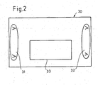
- FIG. 2 shows an example of the implementation of the step "Assign" using a screen 30 on a screen of the IP controller.
- the example is the setting of the "Venetian blind” function.
- the input devices that are suitable for this function can be called, such as buttons, anemometers and the like. The user can then select the relevant input device with a mouse click.
- the desired device can be selected from a group of eligible output devices.
- the properties of the function can be entered, e.g. Time settings for raising or lowering the blind.
- the configuration can also be performed from any other LAN device.
Landscapes
- Engineering & Computer Science (AREA)
- Computer Networks & Wireless Communication (AREA)
- Signal Processing (AREA)
- Automation & Control Theory (AREA)
- Computing Systems (AREA)
- Health & Medical Sciences (AREA)
- General Health & Medical Sciences (AREA)
- Medical Informatics (AREA)
- Small-Scale Networks (AREA)
- Selective Calling Equipment (AREA)
Claims (10)
- Système domotique composé des éléments suivants- un réseau local, LAN (10), qui fonctionne au protocole Internet (IP) et- au moins deux sous-réseaux (SNW1-SNW3) qui sont connectés au réseau local (10) et qui sont reliés entre eux et dont chacun présente un bus de données (EIB1-EIB3) pour le raccordement d'appareils (22) et un configurateur (20),- chaque sous-réseau (SNW1-SNW3) pouvant être configuré par le biais du configurateur (20),a) la structure du sous-réseau (SNW1-SNW3) concerné pouvant être mise en mémoire et gérée dans le configurateur (20), etb) les appareils raccordés au bus de données (EIB1-EIB3) au sein du sous-réseau (SNW1-SNW3) concerné pouvant être dotés d'adresses d'appareil individuelles au moyen du configurateur (20), une affectation des appareils (22) en tant qu'émetteurs et récepteurs pouvant être définie et cette affectation pouvant être mise en mémoire,- et le configurateur (20) formant une interface (20b) à permutation bidirectionnelle entre le LAN (10) et le sous-réseau (SNW1-SNW3)
caractérisé en ce- que le réseau local (10) qui fonctionne au protocole Internet (IP) contient un contrôleur d'IP (24), et- que la configuration des sous-réseaux (SNW1-SNW3) et des appareils (22) raccordés peut être effectuée sur l'ensemble des sous-réseaux avec le contrôleur d'IP (24). - Système domotique selon la revendication 1, caractérisé en ce que le configurateur présente une deuxième interface qui fonctionne au protocole IP pour la connexion d'un autre réseau local.
- Procédé de configuration d'un système domotique, qui présente :- un LAN (10) qui fonctionne au protocole Internet, lequel contient un contrôleur d'IP (24), et- au moins deux sous-réseaux (SNW1-SNW3), dont chacun présente un bus de données (EIB1-EIB3) pour le raccordement d'appareils (22), un convertisseur de protocole (20b) et un configurateur (20),
caractérisé par les étapes suivantes :a) attribution d'adresses IP aux configurateurs et allocation de plages d'adresses pour les adresses d'appareil individuelles et les adresses de groupe par le contrôleur d'IP,b) interrogation et reconnaissance des appareils d'un sous-réseau d'après leur type d'appareil par le configurateur,c) remise d'une adresse d'appareil individuelle aux appareils individuels au sein du sous-réseau par le configurateur,d) communication des types d'appareil et des adresses d'appareil des appareils associés à chaque configurateur par le configurateur au contrôleur d'IP,e) affectation dans le contrôleur d'IP des appareils qui doivent communiquer entre eux en ignorant le configurateur,f) communication de l'affectation du contrôleur d'IP aux appareils respectifs et mise en mémoire dans chaque appareil de l'adresse d'un appareil partenaire correspondant. - Procédé selon la revendication 3, caractérisé par la collecte des affectations de plusieurs appareils (22) dans le contrôleur d'IP (24) et la délivrance des affectations dans un bloc aux configurateurs (20).
- Procédé selon la revendication 3 ou 4, caractérisé en ce que l'étape d'affectation comprend la détermination du lieu d'installation d'un appareil, un signal étant généré sur l'appareil qui se trouve sur son lieu d'installation, lequel est communiqué au contrôleur d'IP (24) par le biais du configurateur (20).
- Procédé selon l'une des revendications 3 à 5, caractérisé en ce que dans le contrôleur d'IP (24) est généré un plan de fonction de plusieurs sous-réseaux, y compris les appareils qui communiquent entre eux en ignorant les configurateurs (20).
- Procédé selon l'une des revendications 3 à 6, caractérisé en ce que dans le contrôleur d'IP (24) est généré un plan d'état de plusieurs sous-réseaux, y compris les états des appareils qui communiquent entre eux en ignorant les configurateurs (20).
- Procédé selon l'une des revendication 3 à 7, caractérisé en ce qu'un serveur Web est installé pour le configurateur d'au moins un sous-réseau, lequel contient un plan de fonction et/ou un plan d'état du sous-réseau et est accessible par l'Internet pour visualiser le plan de fonction et/ou le plan d'état en d'autres endroits.
- Procédé selon l'une des revendications 3 à 8, caractérisé en ce que les paires d'appareils, dont les appareils font partie du même sous-réseau, peuvent être affectées les unes aux autres au niveau du configurateur de ce sous-réseau, le configurateur communiquant cette affectation au contrôleur d'IP.
- Procédé selon l'une des revendications 3 à 9, caractérisé en ce que pour exécuter l'étape « affectation », une fonction (33) à créer est affichée sur un écran (30), pour laquelle les appareils d'entrée et les appareils de sortie possibles sont indiqués en vue de leur sélection par un utilisateur, et en ce que des propriétés de la fonction peuvent être sélectionnées.
Applications Claiming Priority (2)
| Application Number | Priority Date | Filing Date | Title |
|---|---|---|---|
| DE10345737 | 2003-10-01 | ||
| DE10345737A DE10345737A1 (de) | 2003-10-01 | 2003-10-01 | System der Gebäudesystemtechnik und Verfahren zum Konfigurieren |
Publications (2)
| Publication Number | Publication Date |
|---|---|
| EP1521401A1 EP1521401A1 (fr) | 2005-04-06 |
| EP1521401B1 true EP1521401B1 (fr) | 2013-04-10 |
Family
ID=34306188
Family Applications (1)
| Application Number | Title | Priority Date | Filing Date |
|---|---|---|---|
| EP04022509.6A Expired - Lifetime EP1521401B1 (fr) | 2003-10-01 | 2004-09-22 | Système de l'industrie des systèmes batiments et procédée pour la configuration dudit système |
Country Status (3)
| Country | Link |
|---|---|
| EP (1) | EP1521401B1 (fr) |
| DE (1) | DE10345737A1 (fr) |
| ES (1) | ES2420515T3 (fr) |
Cited By (1)
| Publication number | Priority date | Publication date | Assignee | Title |
|---|---|---|---|---|
| CN110647127A (zh) * | 2019-10-17 | 2020-01-03 | 厦门高瑞特电气自动化有限公司 | 一种模块组合的电力过程控制装置及其初始化配置方法 |
Families Citing this family (11)
| Publication number | Priority date | Publication date | Assignee | Title |
|---|---|---|---|---|
| JP4966094B2 (ja) | 2007-05-24 | 2012-07-04 | 株式会社東芝 | 鉄道車両用伝送システム及びそれに用いる伝送装置 |
| DE102007038595B3 (de) * | 2007-08-16 | 2009-02-05 | Raumcomputer Entwicklungs- Und Vertriebs Gmbh | System für integrierte Gebäudedienste |
| CN101919290B (zh) | 2007-11-29 | 2014-04-23 | 可靠网络公司 | 无线和有线网络设计的方法和配置适配器 |
| EP3370370B1 (fr) * | 2008-04-18 | 2020-12-09 | Thierry Schuffenecker | Procédé de communication pour des éléments constitutifs d'un réseau de distribution d'énergie électrique et des dispositifs de mise en oeuvre du procédé |
| US8412789B2 (en) | 2008-08-28 | 2013-04-02 | Robert Bosch Gmbh | System and method for connecting a security system using a network |
| SG179314A1 (en) * | 2010-09-23 | 2012-04-27 | Eutech Cybernetic Pte Ltd | Computer implemented method and system for integrating multiple building systems and business applications |
| DE102011075608A1 (de) * | 2011-05-10 | 2012-11-15 | Siemens Aktiengesellschaft | Verfahren zum Zuordnen eines physikalischen Kanals eines Sensors, der an einen Bus eines Bus-Systems angeschlossen ist, zu einem Kanal eines in einem Inbetriebnahmeprogramm virtuell dargestellten Sensors sowie Sensor und Inbetriebnahmeprogramm |
| DE102011077009A1 (de) * | 2011-06-06 | 2012-12-06 | S. Siedle & Söhne Telefon- und Telegrafenwerke OHG | Hauskommunikationsendgerät, Initialisierungsverfahren für ein Hauskommunikationsendgerät und Hauskommunikationsanlage |
| DE102012210959A1 (de) * | 2012-06-27 | 2014-01-02 | Zumtobel Lighting Gmbh | Steuerungssystem für verteilt angeordnete Verbraucher und Verfahren zur Inbetriebnahme des Systems |
| US9684286B2 (en) | 2013-09-12 | 2017-06-20 | Robert Bosch Gmbh | Security system with point bus abstraction and partitioning |
| DE102014221788A1 (de) * | 2014-10-27 | 2016-04-28 | Zumtobel Lighting Gmbh | Gebäudetechnik-Bussystem zum Betrieb von Gebäudetechnik-Geräten |
Family Cites Families (10)
| Publication number | Priority date | Publication date | Assignee | Title |
|---|---|---|---|---|
| DE3820613A1 (de) * | 1988-06-17 | 1990-02-08 | Merten Gmbh & Co Kg Geb | Digitales signaluebertragungssystem |
| DE19546831A1 (de) * | 1995-12-15 | 1996-06-05 | Janke Peter Dipl Inform Fh | Verfahren zum Managen von Installationen in Gebäuden |
| JP2000004273A (ja) * | 1998-04-16 | 2000-01-07 | Toshiba Corp | 通信プラットフォームlsiシステム、及び同システムに用いられる通信プラットフォームlsi、並びに同システムに於けるその通信制御方法 |
| JP3823585B2 (ja) * | 1999-02-22 | 2006-09-20 | 株式会社日立製作所 | 機器ネットワーク接続方法およびルータ機器 |
| DE50014879D1 (de) * | 1999-08-13 | 2008-02-07 | Fraunhofer Ges Forschung | Haus-kommunikationssystem, transportplattform für ein haus-kommunikationssystem und intelligentes netzabschlussgerät für ein haus-kommunikationssystem |
| DE10042969C2 (de) * | 2000-08-31 | 2003-01-30 | Smartbuilding Ag | Verfahren zum Fernsteuern, sowie Fernsteuersystem |
| DE10125607A1 (de) * | 2001-05-25 | 2002-11-28 | Siemens Ag | Einrichtung zum Datenaustausch zwischen einem Kommunikationsnetz und elektrisch betriebenen Geräten |
| JP2003087293A (ja) * | 2001-09-11 | 2003-03-20 | Hitachi Ltd | ネットワーク装置、ネットワーク制御装置およびネットワーク装置の制御方法 |
| DE10241875B4 (de) * | 2002-09-09 | 2010-09-02 | Gira Giersiepen Gmbh & Co. Kg | Datenverarbeitungssystem |
| DE20304474U1 (de) * | 2003-03-20 | 2003-12-04 | Baurmann, Albert, Dipl.-Ing. | Gerät (Gateway) zur Verbindung der Netze Ethernet (z.B. LAN), ISDN und dem eines Installationsbussystems |
-
2003
- 2003-10-01 DE DE10345737A patent/DE10345737A1/de not_active Withdrawn
-
2004
- 2004-09-22 ES ES04022509T patent/ES2420515T3/es not_active Expired - Lifetime
- 2004-09-22 EP EP04022509.6A patent/EP1521401B1/fr not_active Expired - Lifetime
Cited By (1)
| Publication number | Priority date | Publication date | Assignee | Title |
|---|---|---|---|---|
| CN110647127A (zh) * | 2019-10-17 | 2020-01-03 | 厦门高瑞特电气自动化有限公司 | 一种模块组合的电力过程控制装置及其初始化配置方法 |
Also Published As
| Publication number | Publication date |
|---|---|
| ES2420515T3 (es) | 2013-08-23 |
| EP1521401A1 (fr) | 2005-04-06 |
| DE10345737A1 (de) | 2005-04-21 |
Similar Documents
| Publication | Publication Date | Title |
|---|---|---|
| EP2625822B1 (fr) | Procédé pour configurer un ou plusieurs appareils dans un réseau de communication basé sur ethernet | |
| EP1064759B1 (fr) | Procede de mise en service d'un systeme bus et systeme bus en question | |
| EP1521401B1 (fr) | Système de l'industrie des systèmes batiments et procédée pour la configuration dudit système | |
| EP2506096B1 (fr) | Procédé de combinaison logique de capteurs et d'actionneurs dans le cadre de la mise en service d'un système d'installation | |
| EP1738236B1 (fr) | Reseau d'automatisation a composantes reseau produisant des messages d'etat | |
| DE102008017292A1 (de) | Computergestütztes System zur Verwaltung und/oder Steuerung eines Gebäudemanagementsystems | |
| EP3416337B1 (fr) | Dispositif d'automatisation d'une maison ou d'un bâtiment | |
| EP2667680B1 (fr) | Système d'automatisation de bâtiment | |
| EP3616011B1 (fr) | Dispositif et procédé de surveillance d'un système d'automatisation | |
| EP1237250A2 (fr) | Système domestique | |
| EP1170848A2 (fr) | Système et dispositif de demotique | |
| EP2181527B1 (fr) | Noeud de commande pour un réseau constitué de noeuds de commande | |
| DE10034774A1 (de) | Fernsteuereinrichtung für Antriebe von Schließvorrichtungen für Gebäudeöffnungen | |
| DE10312183A1 (de) | Gebäudeinstallationssystem | |
| DE60114350T2 (de) | Vorrichtung und Verfahren zur Abstandssteuerung von Haushaltsgeräten | |
| DE10056469A1 (de) | Koppeleinrichtung und Koppelverfahren zur Kopplung von lokalen und globalen Netzwerken | |
| DE102004051834B4 (de) | Prüfgerät und Prüfverfahren für programmierbare Elektroinstallationen, sowie entsprechendes Computerprogramm und entsprechendes computerlesbares Speichermedium | |
| DE10012279A1 (de) | System und Verfahren zum grafischen Verschalten von Elektroinstallationskomponenten | |
| EP1222744B1 (fr) | Procede de conversion d'une telecommande | |
| EP3664380B1 (fr) | Concept d'étages pouvant être mis à niveau pour systèmes d'éclairage | |
| DE102022110223A1 (de) | Verfahren zur Erstellung und Überwachung einer Historie von mindestens einem Eingriff an einer Heimautomatisierungsanlage | |
| WO2008040390A1 (fr) | Système d'éclairage et procédé de fonctionnement d'un système d'éclairage | |
| EP3657272A1 (fr) | Appareil de commande pour l'automatisation domotique | |
| DE102024000556A1 (de) | Verfahren zum Betrieb eines Steuergerätes zur Steuerung von Netzwerkswitchen | |
| EP4212975A1 (fr) | Procédé de configuration d'un réseau de commande, ainsi que réseau de commande, programme informatique et support lisible par ordinateur |
Legal Events
| Date | Code | Title | Description |
|---|---|---|---|
| PUAI | Public reference made under article 153(3) epc to a published international application that has entered the european phase |
Free format text: ORIGINAL CODE: 0009012 |
|
| AK | Designated contracting states |
Kind code of ref document: A1 Designated state(s): AT BE BG CH CY CZ DE DK EE ES FI FR GB GR HU IE IT LI LU MC NL PL PT RO SE SI SK TR |
|
| AX | Request for extension of the european patent |
Extension state: AL HR LT LV MK |
|
| 17P | Request for examination filed |
Effective date: 20050914 |
|
| AKX | Designation fees paid |
Designated state(s): AT BE BG CH CY CZ DE DK EE ES FI FR GB GR HU IE IT LI LU MC NL PL PT RO SE SI SK TR |
|
| 17Q | First examination report despatched |
Effective date: 20071123 |
|
| REG | Reference to a national code |
Ref country code: DE Ref legal event code: R079 Ref document number: 502004014102 Country of ref document: DE Free format text: PREVIOUS MAIN CLASS: H04L0012280000 Ipc: H04L0029080000 |
|
| GRAP | Despatch of communication of intention to grant a patent |
Free format text: ORIGINAL CODE: EPIDOSNIGR1 |
|
| RIC1 | Information provided on ipc code assigned before grant |
Ipc: H04L 12/24 20060101ALI20120924BHEP Ipc: H04L 29/06 20060101ALI20120924BHEP Ipc: H04L 12/46 20060101ALI20120924BHEP Ipc: H04L 29/08 20060101AFI20120924BHEP Ipc: H05B 37/02 20060101ALI20120924BHEP Ipc: H04L 12/28 20060101ALI20120924BHEP Ipc: H04L 12/44 20060101ALI20120924BHEP Ipc: H04L 29/12 20060101ALI20120924BHEP |
|
| GRAS | Grant fee paid |
Free format text: ORIGINAL CODE: EPIDOSNIGR3 |
|
| GRAA | (expected) grant |
Free format text: ORIGINAL CODE: 0009210 |
|
| RAP1 | Party data changed (applicant data changed or rights of an application transferred) |
Owner name: MERTEN GMBH |
|
| AK | Designated contracting states |
Kind code of ref document: B1 Designated state(s): AT BE BG CH CY CZ DE DK EE ES FI FR GB GR HU IE IT LI LU MC NL PL PT RO SE SI SK TR |
|
| REG | Reference to a national code |
Ref country code: GB Ref legal event code: FG4D Free format text: NOT ENGLISH |
|
| REG | Reference to a national code |
Ref country code: CH Ref legal event code: EP Ref country code: AT Ref legal event code: REF Ref document number: 606553 Country of ref document: AT Kind code of ref document: T Effective date: 20130415 |
|
| REG | Reference to a national code |
Ref country code: IE Ref legal event code: FG4D Free format text: LANGUAGE OF EP DOCUMENT: GERMAN |
|
| REG | Reference to a national code |
Ref country code: DE Ref legal event code: R096 Ref document number: 502004014102 Country of ref document: DE Effective date: 20130606 |
|
| REG | Reference to a national code |
Ref country code: ES Ref legal event code: FG2A Ref document number: 2420515 Country of ref document: ES Kind code of ref document: T3 Effective date: 20130823 |
|
| PG25 | Lapsed in a contracting state [announced via postgrant information from national office to epo] |
Ref country code: SI Free format text: LAPSE BECAUSE OF FAILURE TO SUBMIT A TRANSLATION OF THE DESCRIPTION OR TO PAY THE FEE WITHIN THE PRESCRIBED TIME-LIMIT Effective date: 20130410 |
|
| REG | Reference to a national code |
Ref country code: NL Ref legal event code: VDEP Effective date: 20130410 |
|
| PG25 | Lapsed in a contracting state [announced via postgrant information from national office to epo] |
Ref country code: SE Free format text: LAPSE BECAUSE OF FAILURE TO SUBMIT A TRANSLATION OF THE DESCRIPTION OR TO PAY THE FEE WITHIN THE PRESCRIBED TIME-LIMIT Effective date: 20130410 Ref country code: GR Free format text: LAPSE BECAUSE OF FAILURE TO SUBMIT A TRANSLATION OF THE DESCRIPTION OR TO PAY THE FEE WITHIN THE PRESCRIBED TIME-LIMIT Effective date: 20130711 Ref country code: FI Free format text: LAPSE BECAUSE OF FAILURE TO SUBMIT A TRANSLATION OF THE DESCRIPTION OR TO PAY THE FEE WITHIN THE PRESCRIBED TIME-LIMIT Effective date: 20130410 Ref country code: PT Free format text: LAPSE BECAUSE OF FAILURE TO SUBMIT A TRANSLATION OF THE DESCRIPTION OR TO PAY THE FEE WITHIN THE PRESCRIBED TIME-LIMIT Effective date: 20130812 Ref country code: NL Free format text: LAPSE BECAUSE OF FAILURE TO SUBMIT A TRANSLATION OF THE DESCRIPTION OR TO PAY THE FEE WITHIN THE PRESCRIBED TIME-LIMIT Effective date: 20130410 |
|
| PG25 | Lapsed in a contracting state [announced via postgrant information from national office to epo] |
Ref country code: PL Free format text: LAPSE BECAUSE OF FAILURE TO SUBMIT A TRANSLATION OF THE DESCRIPTION OR TO PAY THE FEE WITHIN THE PRESCRIBED TIME-LIMIT Effective date: 20130410 Ref country code: BG Free format text: LAPSE BECAUSE OF FAILURE TO SUBMIT A TRANSLATION OF THE DESCRIPTION OR TO PAY THE FEE WITHIN THE PRESCRIBED TIME-LIMIT Effective date: 20130710 Ref country code: CY Free format text: LAPSE BECAUSE OF FAILURE TO SUBMIT A TRANSLATION OF THE DESCRIPTION OR TO PAY THE FEE WITHIN THE PRESCRIBED TIME-LIMIT Effective date: 20130410 |
|
| PG25 | Lapsed in a contracting state [announced via postgrant information from national office to epo] |
Ref country code: DK Free format text: LAPSE BECAUSE OF FAILURE TO SUBMIT A TRANSLATION OF THE DESCRIPTION OR TO PAY THE FEE WITHIN THE PRESCRIBED TIME-LIMIT Effective date: 20130410 Ref country code: CZ Free format text: LAPSE BECAUSE OF FAILURE TO SUBMIT A TRANSLATION OF THE DESCRIPTION OR TO PAY THE FEE WITHIN THE PRESCRIBED TIME-LIMIT Effective date: 20130410 Ref country code: EE Free format text: LAPSE BECAUSE OF FAILURE TO SUBMIT A TRANSLATION OF THE DESCRIPTION OR TO PAY THE FEE WITHIN THE PRESCRIBED TIME-LIMIT Effective date: 20130410 Ref country code: SK Free format text: LAPSE BECAUSE OF FAILURE TO SUBMIT A TRANSLATION OF THE DESCRIPTION OR TO PAY THE FEE WITHIN THE PRESCRIBED TIME-LIMIT Effective date: 20130410 |
|
| PLBE | No opposition filed within time limit |
Free format text: ORIGINAL CODE: 0009261 |
|
| STAA | Information on the status of an ep patent application or granted ep patent |
Free format text: STATUS: NO OPPOSITION FILED WITHIN TIME LIMIT |
|
| PG25 | Lapsed in a contracting state [announced via postgrant information from national office to epo] |
Ref country code: RO Free format text: LAPSE BECAUSE OF FAILURE TO SUBMIT A TRANSLATION OF THE DESCRIPTION OR TO PAY THE FEE WITHIN THE PRESCRIBED TIME-LIMIT Effective date: 20130410 |
|
| 26N | No opposition filed |
Effective date: 20140113 |
|
| BERE | Be: lapsed |
Owner name: MERTEN G.M.B.H. Effective date: 20130930 |
|
| REG | Reference to a national code |
Ref country code: DE Ref legal event code: R097 Ref document number: 502004014102 Country of ref document: DE Effective date: 20140113 |
|
| PG25 | Lapsed in a contracting state [announced via postgrant information from national office to epo] |
Ref country code: MC Free format text: LAPSE BECAUSE OF FAILURE TO SUBMIT A TRANSLATION OF THE DESCRIPTION OR TO PAY THE FEE WITHIN THE PRESCRIBED TIME-LIMIT Effective date: 20130410 |
|
| REG | Reference to a national code |
Ref country code: CH Ref legal event code: PL |
|
| GBPC | Gb: european patent ceased through non-payment of renewal fee |
Effective date: 20130922 |
|
| REG | Reference to a national code |
Ref country code: IE Ref legal event code: MM4A |
|
| PG25 | Lapsed in a contracting state [announced via postgrant information from national office to epo] |
Ref country code: IE Free format text: LAPSE BECAUSE OF NON-PAYMENT OF DUE FEES Effective date: 20130922 Ref country code: LI Free format text: LAPSE BECAUSE OF NON-PAYMENT OF DUE FEES Effective date: 20130930 Ref country code: CH Free format text: LAPSE BECAUSE OF NON-PAYMENT OF DUE FEES Effective date: 20130930 Ref country code: BE Free format text: LAPSE BECAUSE OF NON-PAYMENT OF DUE FEES Effective date: 20130930 Ref country code: GB Free format text: LAPSE BECAUSE OF NON-PAYMENT OF DUE FEES Effective date: 20130922 |
|
| REG | Reference to a national code |
Ref country code: AT Ref legal event code: MM01 Ref document number: 606553 Country of ref document: AT Kind code of ref document: T Effective date: 20130922 |
|
| PG25 | Lapsed in a contracting state [announced via postgrant information from national office to epo] |
Ref country code: AT Free format text: LAPSE BECAUSE OF NON-PAYMENT OF DUE FEES Effective date: 20130922 |
|
| PG25 | Lapsed in a contracting state [announced via postgrant information from national office to epo] |
Ref country code: TR Free format text: LAPSE BECAUSE OF FAILURE TO SUBMIT A TRANSLATION OF THE DESCRIPTION OR TO PAY THE FEE WITHIN THE PRESCRIBED TIME-LIMIT Effective date: 20130410 |
|
| PG25 | Lapsed in a contracting state [announced via postgrant information from national office to epo] |
Ref country code: HU Free format text: LAPSE BECAUSE OF FAILURE TO SUBMIT A TRANSLATION OF THE DESCRIPTION OR TO PAY THE FEE WITHIN THE PRESCRIBED TIME-LIMIT; INVALID AB INITIO Effective date: 20040922 Ref country code: LU Free format text: LAPSE BECAUSE OF NON-PAYMENT OF DUE FEES Effective date: 20130922 |
|
| REG | Reference to a national code |
Ref country code: FR Ref legal event code: PLFP Year of fee payment: 12 |
|
| REG | Reference to a national code |
Ref country code: FR Ref legal event code: PLFP Year of fee payment: 13 |
|
| PGFP | Annual fee paid to national office [announced via postgrant information from national office to epo] |
Ref country code: IT Payment date: 20160921 Year of fee payment: 13 |
|
| REG | Reference to a national code |
Ref country code: FR Ref legal event code: PLFP Year of fee payment: 14 |
|
| REG | Reference to a national code |
Ref country code: FR Ref legal event code: PLFP Year of fee payment: 15 |
|
| PG25 | Lapsed in a contracting state [announced via postgrant information from national office to epo] |
Ref country code: IT Free format text: LAPSE BECAUSE OF NON-PAYMENT OF DUE FEES Effective date: 20170922 |
|
| REG | Reference to a national code |
Ref country code: DE Ref legal event code: R079 Ref document number: 502004014102 Country of ref document: DE Free format text: PREVIOUS MAIN CLASS: H04L0029080000 Ipc: H04L0065000000 |
|
| PGFP | Annual fee paid to national office [announced via postgrant information from national office to epo] |
Ref country code: FR Payment date: 20230808 Year of fee payment: 20 Ref country code: DE Payment date: 20230802 Year of fee payment: 20 |
|
| PGFP | Annual fee paid to national office [announced via postgrant information from national office to epo] |
Ref country code: ES Payment date: 20231009 Year of fee payment: 20 |
|
| REG | Reference to a national code |
Ref country code: DE Ref legal event code: R071 Ref document number: 502004014102 Country of ref document: DE |
|
| REG | Reference to a national code |
Ref country code: ES Ref legal event code: FD2A Effective date: 20240927 |
|
| PG25 | Lapsed in a contracting state [announced via postgrant information from national office to epo] |
Ref country code: ES Free format text: LAPSE BECAUSE OF EXPIRATION OF PROTECTION Effective date: 20240923 |
|
| PG25 | Lapsed in a contracting state [announced via postgrant information from national office to epo] |
Ref country code: ES Free format text: LAPSE BECAUSE OF EXPIRATION OF PROTECTION Effective date: 20240923 |