EP1521401B1 - System der Gebäudesystemtechnik und Verfahren zum Konfigurieren desselben - Google Patents
System der Gebäudesystemtechnik und Verfahren zum Konfigurieren desselben Download PDFInfo
- Publication number
- EP1521401B1 EP1521401B1 EP04022509.6A EP04022509A EP1521401B1 EP 1521401 B1 EP1521401 B1 EP 1521401B1 EP 04022509 A EP04022509 A EP 04022509A EP 1521401 B1 EP1521401 B1 EP 1521401B1
- Authority
- EP
- European Patent Office
- Prior art keywords
- devices
- configurator
- controller
- subnetwork
- subnetworks
- Prior art date
- Legal status (The legal status is an assumption and is not a legal conclusion. Google has not performed a legal analysis and makes no representation as to the accuracy of the status listed.)
- Expired - Lifetime
Links
Images

Classifications
-
- H—ELECTRICITY
- H04—ELECTRIC COMMUNICATION TECHNIQUE
- H04L—TRANSMISSION OF DIGITAL INFORMATION, e.g. TELEGRAPHIC COMMUNICATION
- H04L12/00—Data switching networks
- H04L12/28—Data switching networks characterised by path configuration, e.g. LAN [Local Area Networks] or WAN [Wide Area Networks]
- H04L12/2803—Home automation networks
-
- H—ELECTRICITY
- H05—ELECTRIC TECHNIQUES NOT OTHERWISE PROVIDED FOR
- H05B—ELECTRIC HEATING; ELECTRIC LIGHT SOURCES NOT OTHERWISE PROVIDED FOR; CIRCUIT ARRANGEMENTS FOR ELECTRIC LIGHT SOURCES, IN GENERAL
- H05B47/00—Circuit arrangements for operating light sources in general, i.e. where the type of light source is not relevant
- H05B47/10—Controlling the light source
- H05B47/175—Controlling the light source by remote control
- H05B47/18—Controlling the light source by remote control via data-bus transmission
-
- H—ELECTRICITY
- H04—ELECTRIC COMMUNICATION TECHNIQUE
- H04L—TRANSMISSION OF DIGITAL INFORMATION, e.g. TELEGRAPHIC COMMUNICATION
- H04L12/00—Data switching networks
- H04L12/28—Data switching networks characterised by path configuration, e.g. LAN [Local Area Networks] or WAN [Wide Area Networks]
- H04L12/2803—Home automation networks
- H04L12/283—Processing of data at an internetworking point of a home automation network
-
- H—ELECTRICITY
- H04—ELECTRIC COMMUNICATION TECHNIQUE
- H04L—TRANSMISSION OF DIGITAL INFORMATION, e.g. TELEGRAPHIC COMMUNICATION
- H04L12/00—Data switching networks
- H04L12/28—Data switching networks characterised by path configuration, e.g. LAN [Local Area Networks] or WAN [Wide Area Networks]
- H04L12/44—Star or tree networks
-
- H—ELECTRICITY
- H04—ELECTRIC COMMUNICATION TECHNIQUE
- H04L—TRANSMISSION OF DIGITAL INFORMATION, e.g. TELEGRAPHIC COMMUNICATION
- H04L12/00—Data switching networks
- H04L12/28—Data switching networks characterised by path configuration, e.g. LAN [Local Area Networks] or WAN [Wide Area Networks]
- H04L12/46—Interconnection of networks
- H04L12/4604—LAN interconnection over a backbone network, e.g. Internet, Frame Relay
-
- H—ELECTRICITY
- H04—ELECTRIC COMMUNICATION TECHNIQUE
- H04L—TRANSMISSION OF DIGITAL INFORMATION, e.g. TELEGRAPHIC COMMUNICATION
- H04L41/00—Arrangements for maintenance, administration or management of data switching networks, e.g. of packet switching networks
- H04L41/08—Configuration management of networks or network elements
- H04L41/0803—Configuration setting
-
- H—ELECTRICITY
- H04—ELECTRIC COMMUNICATION TECHNIQUE
- H04L—TRANSMISSION OF DIGITAL INFORMATION, e.g. TELEGRAPHIC COMMUNICATION
- H04L41/00—Arrangements for maintenance, administration or management of data switching networks, e.g. of packet switching networks
- H04L41/08—Configuration management of networks or network elements
- H04L41/0803—Configuration setting
- H04L41/0806—Configuration setting for initial configuration or provisioning, e.g. plug-and-play
-
- H—ELECTRICITY
- H04—ELECTRIC COMMUNICATION TECHNIQUE
- H04L—TRANSMISSION OF DIGITAL INFORMATION, e.g. TELEGRAPHIC COMMUNICATION
- H04L61/00—Network arrangements, protocols or services for addressing or naming
- H04L61/50—Address allocation
- H04L61/5038—Address allocation for local use, e.g. in LAN or USB networks, or in a controller area network [CAN]
-
- H—ELECTRICITY
- H04—ELECTRIC COMMUNICATION TECHNIQUE
- H04L—TRANSMISSION OF DIGITAL INFORMATION, e.g. TELEGRAPHIC COMMUNICATION
- H04L67/00—Network arrangements or protocols for supporting network services or applications
- H04L67/01—Protocols
- H04L67/12—Protocols specially adapted for proprietary or special-purpose networking environments, e.g. medical networks, sensor networks, networks in vehicles or remote metering networks
-
- H—ELECTRICITY
- H04—ELECTRIC COMMUNICATION TECHNIQUE
- H04B—TRANSMISSION
- H04B2203/00—Indexing scheme relating to line transmission systems
- H04B2203/54—Aspects of powerline communications not already covered by H04B3/54 and its subgroups
- H04B2203/5429—Applications for powerline communications
- H04B2203/5445—Local network
-
- H—ELECTRICITY
- H04—ELECTRIC COMMUNICATION TECHNIQUE
- H04L—TRANSMISSION OF DIGITAL INFORMATION, e.g. TELEGRAPHIC COMMUNICATION
- H04L69/00—Network arrangements, protocols or services independent of the application payload and not provided for in the other groups of this subclass
- H04L69/30—Definitions, standards or architectural aspects of layered protocol stacks
- H04L69/32—Architecture of open systems interconnection [OSI] 7-layer type protocol stacks, e.g. the interfaces between the data link level and the physical level
- H04L69/322—Intralayer communication protocols among peer entities or protocol data unit [PDU] definitions
- H04L69/329—Intralayer communication protocols among peer entities or protocol data unit [PDU] definitions in the application layer [OSI layer 7]
Definitions
- the invention relates to a system of building system technology, consisting of an Internet protocol (IP) operated local area network (LAN) and at least one sub-network having a data bus for the connection of devices and a configurator.
- IP Internet protocol
- LAN local area network
- the invention further relates to a method for configuring a building system technology system that contains different network structures in a hierarchical assignment.
- the building system technology provides a bus system in which a data bus is installed in a building to which devices are connected.
- the devices can communicate with each other via data telegrams transmitted via the data bus. In this way, information or commands can be exchanged between two devices.
- Such an instruction may include lighting in a certain area of a building or retracting an awning because an anemometer has detected an increased wind speed or a shutter is being operated at a certain time.
- a standardized bus system for building system technology is the EIB bus (European Installation Bus). This bus system connects the connected devices, which exchange bus telegrams with each other. A central office is not provided.
- EIB Tool Software In EIB objects, a special tool that does not remain in the bus system, the EIB Tool Software (ETS), is required for configuration, commissioning and maintenance. The user wishing to make a change or other intervention must entrust this task to a specialist who is specially trained and equipped with the necessary software tools. This person must carry out the required activities on site.
- EMS EIB Tool Software
- EP 0 346 614 B1 (Merten et al ) describes a method for initializing and operating such a building system technology system. After the data bus has been laid, any devices intended for the bus can be installed at the connection points. There is a distinction between different types of devices. Device types are, for example, sensors for brightness, temperature, wind and the like, and actuators, such as switches, dimmers, motors or other actuators.
- Device types are, for example, sensors for brightness, temperature, wind and the like, and actuators, such as switches, dimmers, motors or other actuators.
- Initialization involves defining those device groups whose devices are interconnected should communicate. The address and the type of the respective partner devices are stored in each device. In this way, the devices can then communicate with each other. For initialization, a configurator is used.
- the entry of the installation location of a device takes place in that the installed device is activated by a switching or assembly process performed on it. This generates an activation signal, which is communicated to the configurator.
- the installer can then tell the location where he has performed the switching or signaling process to the configurator so that the device in question is identified both by device type and by its installation location.
- the configurator can then be used to assign those devices in pairs, which should communicate with each other.
- This method which requires switching on every single installed device, is also referred to as a "sneaker method" because it requires a lot of running work.
- Another initialization provides that the configurator calls identifiers of the individual connection points for devices one after the other and the connection points to the call have responding signal generator, whereby the location of the connection point is identifiable when responding to a signal generator.
- All devices have the same default value for the individual address ex factory.
- the devices are automatically assigned and programmed by the configurator with the help of the serial number or the connection sequence.
- the configurator queries the devices for the standardized channel information, such as the number of device channels and the type of device channels (eg dimming, switching, switching with feedback). From the type information of the device channels, the configurator provides an internal list with information about the subordinate network.
- the communication between the devices takes place as in the standard EIB system via so-called group addresses.
- the devices are loaded by the configurator with provisional group addresses.
- sensor channels or actuator channels can be detected by a trial operation.
- the devices that are to form a function together eg buttons and dimmers
- the selection of devices is supported and monitored by the configurator based on the type information about the device channels and connection rules.
- the assignment and programming of the actual group addresses in the devices takes place according to the Easy connection mechanism, whereby the communication relationships are defined and the configuration of a functional area is completed.
- the EIBeasy method connects a configurator to the data bus to initialize or program the system. It is a pure installation process that the electrician can do without the use of complex software.
- a system of building system technology consisting of a LAN operated in the IP protocol and at least one connected sub-network, which includes a data bus for the connection of devices.
- Each device has its own configuration block, so that a decentralized configuration of the network takes place.
- EP-A-1 294 132 concerns a system with several subnetworks, each network-specific configured. Options for network-wide communication of devices are not described.
- the invention has for its object to provide a system of building system technology that is LAN-compatible and allows networking of sub-networks, each based on a local data bus, with a cross-system communication of devices is possible.
- each of the data bus-based subnetworks is equipped with a permanently installed configurator containing information about the subnetwork devices and in turn forms at least one interface for communication with a higher-level IP controller and the higher-level LAN.
- IP interfaces there is more than one IP interface on the configurator, it is particularly easy to implement an "internal house network" in a residential complex that is only available to internal services. This central functions can be passed through from top to bottom.
- Functions that affect several areas in execution and are triggered in one area can forward the IP system to the areas concerned.
- the IP controller manages the associated subnetworks, which may be located remotely from each other. In this way it is possible to network several sub-networks with each other.
- the IP controller assumes the mutual association of the devices as sender and receiver in any case if they belong to different sub-networks. After the configuration the communication takes place between these devices across the configurator and the LAN. Although the data transmission in the higher-level network and the sub-networks takes place according to different protocols, communication in both directions is possible via the configurators, which form a bidirectionally converting interface.
- the configurators thus have two tasks, namely the one hand, the storage and management of the structure of the sub-network and on the other hand, the implementation between the bus protocol and Internet Protocol.
- the invention enables the networking of several EIB systems and, on the other hand, a complete data management of the superordinate overall system, which stores the configuration and parameters of the device communication.
- the data management function is performed by the IP controller that belongs to the higher-level LAN. All data is stored in a corresponding block. This simplifies maintenance and service because the data or its image can be accessed centrally. It is possible to make changes from any point on the LAN. It is therefore not necessary for changes to be made by a plumber present at the site of the change.
- visualizations can be done by standard browsers. Interventions and parameterizations can thus be carried out by authorized persons easily and directly via corresponding screen masks. Important messages, such as alarm messages, from the individual areas can be displayed in a control center.
- IP Internet Protocol
- EIB Electronic mail address
- the function of configuring across several subnetworks is taken over by the IP controller, which has access to the individual configurators and can thus retrieve the configuration within a subnetwork.
- the IP controller thus contains all the configuration data and possibly the status information of the network, which is composed of the sub-networks and managed in the Internet Protocol.
- a function to be configured is displayed for performing the step "Assign" on a screen, to which the possible input devices and output devices for selection by a user are specified, and that properties of the function, e.g. a time of execution, can be selected.
- properties of the function e.g. a time of execution
- a desired function can be realized for a particular location.
- the location where the input signal is generated and the location where the function is to be executed are also defined by the user.
- a LAN 10 is provided, which is operated in the Internet Protocol IP.
- the LAN 10 is, for example, an Ethernet.
- the IP communication links are shaded.
- the LAN 10 contains at branch points a distributor 11, which is designed as a hub or switch and connects each of a plurality of branch lines bidirectionally with a main line. Connected to the branch lines are data devices, such as a PC 12, a laptop 13, a WLAN (Wireless Local Area Network) 14 in combination with a PDA (Personal Digital Assistant) 15.
- a configurator 20 is connected to a respective port of a distributor 11 , This contains a connection 20a for the communication with the LAN 10 and a protocol converter 20b for the bidirectional implementation between IP and EIB protocol.
- Each configurator 20 is part of a sub-network SNW1, SNW2, SNW3, which contains an EIB bus EIB1, EIB2, EIB3 operated according to the EIB standard.
- the bus has several connection points, to each of which a device 22 is connected.
- the devices 22 can exchange bus telegrams with each other.
- the devices 22 are of different types, such as switches, sensors of different types, and actuators of different types. In the configuration, certain combinations of devices 22 are established which communicate with each other via the bus in question.
- the bus protocol according to which the local data bus is operated and which is understandable by the devices 22 differs from the IP protocol by which the LAN 10 is operated.
- IP controller 24 which performs the configuration and management of the sub-networks.
- memory 26 which receives the system data of the building system technology and provides for the higher-level building control system GLT.
- Building system technology includes a networked bus system made up of devices for installation technology. The building system technology may be part of a higher-level building control system GLT, z. B. also contains elevator controls and other controls.
- the individual devices 22 When installing a data bus, the individual devices 22 are installed in wall boxes. Thereafter, the configuration is carried out according to the initially described EIBeasy method. Each installation location is assigned a specific device type. Subsequently, the associated configurator 20 queries the devices 22 according to their type. Then the device type is stored for each device. The prerequisite here is that the two devices, which should each communicate with each other, belong to the same subnetwork.
- the configuration is performed on the configurator 20. It is carried out according to the EIBeasy procedure as described in EP 0 346 614 B1 is described.
- the connected devices and the already performed local configurations are communicated to the IP controller 24 by the configurator 20.
- the IP controller has information about the devices according to their functions, their device type and information about the possible partner device. This is followed by the selection of the devices that should form a function with each other across subnets by the user on site, eg. B. by trial operation. After completing the entry by corresponding acknowledgment, the data is downloaded to generate the functions in the devices 22 Each device 22 stores the group address of the communication partners.
- IP controller To speed up the programming process, all information is collected in the IP controller and then transferred en bloc to the configurator 20, which then takes over the distribution to the devices 22.
- the memory 26 stores a functional diagram of the overall network comprising several subnetworks. This function diagram lists the devices 22 with their communication designations as well as the installation locations and device types.
- the memory 26 may include a status plan.
- the status plan indicates the current state of the devices, such as the on state or the off state of a switch, the temperature instantaneously measured by a temperature sensor, and the like.
- the function plan and the status plan can be retrieved and transmitted to other participants of the LAN, so that each participant, if he has an authorized network access, can receive this data.
- a data backup can be done by moving the function diagram onto a transportable medium, e.g. Compact Flash, is saved.
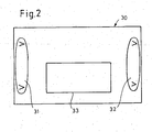
- FIG. 2 shows an example of the implementation of the step "Assign" using a screen 30 on a screen of the IP controller.
- the example is the setting of the "Venetian blind” function.
- the input devices that are suitable for this function can be called, such as buttons, anemometers and the like. The user can then select the relevant input device with a mouse click.
- the desired device can be selected from a group of eligible output devices.
- the properties of the function can be entered, e.g. Time settings for raising or lowering the blind.
- the configuration can also be performed from any other LAN device.
Landscapes
- Engineering & Computer Science (AREA)
- Computer Networks & Wireless Communication (AREA)
- Signal Processing (AREA)
- Automation & Control Theory (AREA)
- Computing Systems (AREA)
- Health & Medical Sciences (AREA)
- General Health & Medical Sciences (AREA)
- Medical Informatics (AREA)
- Small-Scale Networks (AREA)
- Selective Calling Equipment (AREA)
Description
- Die Erfindung betrifft ein System der Gebäudesystemtechnik, bestehend aus einem im Internet-Protokoll (IP) betriebenen lokalen Netzwerk (LAN) und mindestens einem Sub-Netzwerk, das einen Datenbus für den Anschluss von Geräten und einen Konfigurator aufweist.
- Die Erfindung betrifft ferner ein Verfahren zum Konfigurieren eines Gebäudesystemtechnik-Systems, das unterschiedliche Netzstrukturen in hierarchischer Zuordnung enthält.
- Die Gebäudesystemtechnik sieht ein Bussystem vor, bei dem in einem Gebäude ein Datenbus installiert wird, an welchen Geräte angeschlossen werden. Die Geräte können über Datentelegramme, die über den Datenbus übertragen werden, miteinander kommunizieren. Auf diese Weise können Informationen oder Befehle zwischen zwei Geräten ausgetauscht werden. Ein solcher Befehl kann zum Inhalt haben, dass die Beleuchtung in einem bestimmten Bereich eines Gebäudes eingeschaltet werden soll oder dass eine Markise eingefahren werden soll, weil ein Windmesser eine erhöhte Windgeschwindigkeit festgestellt hat, oder dass eine Jalousie zu einem bestimmten Zeitpunkt betätigt werden soll. Ein genormtes Bussystem für die Gebäudesystemtechnik ist der EIB-Bus (European Installation Bus). Dieses Bussystem verbindet die angeschlossenen Geräte, die untereinander Bustelegramme austauschen. Eine Zentrale ist dabei nicht vorgesehen.
- In EIB-Objekten ist zur Konfiguration, Inbetriebnahme und Pflege ein spezielles, nicht im Bussystem verbleibendes Tool, die EIB-Tool-Software (ETS) notwendig. Der Nutzer, der eine Änderung oder einen anderen Eingriff vornehmen will, muss einen speziell ausgebildeten und mit den notwendigen Software-Werkzeugen ausgestatteten Fachmann mit dieser Aufgabe betrauen. Dieser muss die erforderlichen Tätigkeiten vor Ort durchführen.
-
EP 0 346 614 B1 (Merten et al ) beschreibt ein Verfahren zur Initialisierung und zum Betrieb eines derartigen Systems der Gebäudesystemtechnik. Nach dem Verlegen des Datenbusses können an den Anschlussstellen beliebige Geräte installiert werden, die für den Bus vorgesehen sind. Dabei ist zwischen unterschiedlichen Gerätetypen zu unterscheiden. Gerätetypen sind beispielsweise Sensoren für Helligkeit, Temperatur, Wind u.dgl., und Aktoren, wie Schalter, Dimmer, Motoren oder andere Stellglieder. Beim Installieren eines Bussystems werden zunächst die einzelnen Geräte an den dafür vorgesehenen Stellen montiert und mit dem Bus verbunden. Das Initialisieren sieht vor, dass diejenigen Gerätegruppierungen definiert werden, deren Geräte miteinander kommunizieren sollen. In jedem Gerät wird die Adresse und der Typ der jeweiligen Partner-Geräte hinterlegt. Auf diese Weise können die Geräte anschließend miteinander kommunizieren. Zum Initialisieren wird ein Konfigurator benutzt. Hierbei handelt es sich um ein Programmiergerät, das vorübergehend an den Bus angeschlossen werden kann. Die Eingabe des Installationsortes eines Gerätes erfolgt dadurch, dass das installierte Gerät durch einen an ihm durchgeführten Schalt- oder Montagevorgang aktiviert wird. Dadurch wird ein Aktivierungssignal erzeugt, das dem Konfigurator mitgeteilt wird. Der Installateur kann dann den Ort, an dem er den Schalt- oder Meldevorgang durchgeführt hat, dem Konfigurator mitteilen, so dass das betreffende Gerät sowohl nach Gerätetyp als auch nach seinem Installationsort identifiziert ist. Am Konfigurator kann dann die paarweise Zuordnung derjenigen Geräte erfolgen, die miteinander kommunizieren sollen. Diese Methode, die einen Schaltvorgang an jedem einzelnen installierten Gerät erfordert, wird auch als "Turnschuh-Methode" bezeichnet, weil sie viel Laufarbeit erfordert. Eine andere Initialisierung sieht vor, dass der Konfigurator Kennungen der einzelnen Anschlussstellen für Geräte nacheinander aufruft und die Anschlussstellen auf den Aufruf reagierende Signalgeber aufweisen, wodurch beim Ansprechen eines Signalgebers der Ort der Anschlussstelle identifizierbar ist. - Ein Verfahren, das als EIBeasy-Verfahren Eingang in die Praxis gefunden hat, arbeitet wie folgt:
- Alle Geräte haben ab Werk den gleichen default-Wert für die individuelle Adresse. Im Projekt wird den Geräten mit Hilfe der Seriennummer oder der Anschlussreihenfolge vollautomatisch vom Konfigurator eine eindeutige individuelle Adresse zugeordnet und programmiert.
Danach fragt der Konfigurator aus den Geräten die standardisierte Kanalinformation, wie Anzahl der Gerätekanäle und Typ der Gerätekanäle (z. B. Dimmen, Schalten, Schalten mit Rückmeldung), ab. Aus den Typinformationen der Gerätekanäle wird vom Konfigurator eine interne Liste mit Information über das unterlagerte Netzwerk bereitgestellt. - Die Kommunikation zwischen den Geräten erfolgt wie beim Standard-EIB-System über sogenannte Gruppenadressen. In der Konfigurationsphase werden die Geräte vom Konfigurator mit provisorischen Gruppenadressen geladen. Mit Hilfe der provisorischen Gruppenadressen können Sensorkanäle bzw. Aktorkanäle durch eine Probebetätigung erkannt werden. Auf diese Weise werden die Geräte, die zusammen eine Funktion bilden sollen (z. B. Taster und Dimmer), ausgewählt. Die Auswahl der Geräte wird vom Konfigurator auf der Basis der Typinformationen zu den Gerätekanälen und Verbindungsregeln unterstützt und überwacht.
- Nach Zuordnung der Gerätekanäle erfolgt nach dem Easy-Verbindungsmechanismus die Vergabe und Programmierung der eigentlichen Gruppenadressen in den Geräten, wodurch die Kommunikationsbeziehungen festgelegt sind und die Konfiguration eines Funktionsbereiches abgeschlossen ist.
- Bei dem EIBeasy-Verfahren wird ein Konfigurator an den Datenbus angeschlossen, um die Initialisierung bzw. Programmierung des Systems vorzunehmen. Es handelt sich um ein reines Installationsverfahren, das der Elektriker ohne Verwendung einer komplexen Software ausführen kann.
- Des weiteren Ist aus der
US-B1 6 522 664 ein System der Gebäudesystemtechnik bekannt, bestehend aus einem im IP-Protokoll betriebenen LAN und mindestens einem daran angeschlossenen Sub-Netzwerk, das einen Datenbus für den Anschluss von Geräten umfasst. Jedes Gerät weist einen eigenen Konfigurationsbaustein auf, so dass eine dezentrale Konfiguration des Netzwerks erfolgt. -
EP-A-1 294 132 betrifft ein System mit mehreren Subnetzwerken, die jeweils netzwerkspezifisch konfiguriert werden. Möglichkeiten zur netzwerkübergreifenden Kommunikation von Geräten sind nicht beschrieben. - Der Erfindung liegt die Aufgabe zugrunde, ein System der Gebäudesystemtechnik zu schaffen, das LAN-kompatibel ist und eine Vernetzung von Sub-Netzwerken, die jeweils auf einem lokalen Datenbus basieren, ermöglicht, wobei eine systemübergreifende Kommunikation von Geräten möglich ist.
- Das erfindungsgemäße System der Gebäudesystemtechnik ist durch den Patentanspruch 1 definiert. Hiernach ist jedes der Datenbus-basierten Sub-Netzwerke mit einem bleibend installierten Konfigurator ausgestattet, der Informationen über die dem Sub-Netzwerk angehörenden Geräte enthält und seinerseits mindestens eine Schnittstelle für die Kommunikation mit einem übergeordneten IP-Controller und dem übergeordneten LAN bildet.
- Durch dieses Konzept sind gegenüber der seitherigen EIB-Ausprägung weitere Dienste in standardisierter Form und damit kostengünstig realisierbar. Eine nicht notwendige vollständige Auflistung ist nach nachfolgend gegeben.
Web-Server für ein unterlagertes EIB-System Konfiguration Parametrierung Visualisierung e-mail-Dienste Zustandsmeldungen SMS-Ausgabe Alarmierung telnet/ftp Administration des Systems Trouble-Shooting Fernwirken - In einer Erweiterung können mehrere derartige Systeme parallel nebeneinander betrieben werden. Sinnvollerweise werden diese dann über die IP-Schnittstellen miteinander vernetzt. Bei mehr als einer IP-Schnittstelle am Konfigurator lässt sich zum Beispiel in einer Wohnanlage ein "internes Hausnetz" besonders einfach realisieren, das nur internen Diensten zur Verfügung steht. Dadurch können Zentralfunktionen von oben nach unten durchgereicht werden.
- Funktionen, die in der Ausführung mehrere Bereiche betreffen und in einem Bereich ausgelöst werden, kann das IP-System an die betreffenden Bereiche weiterleiten.
- Der IP-Controller verwaltet die zugehörigen Sub-Netzwerke, die räumlich entfernt voneinander angeordnet sein können. Auf diese Weise besteht die Möglichkeit, mehrere Sub-Netzwerke untereinander zu vernetzen. Erfindungsgemäß übernimmt der IP-Controller die gegenseitige Zuordnung der Geräte als Sender und Empfänger jedenfalls dann, wenn sie unterschiedlichen Sub-Netzwerken angehören. Nach der Konfiguration erfolgt die Kommunikation zwischen diesen Geräten über den Konfigurator und das LAN hinweg. Obwohl die Datenübertragung in dem übergeordneten Netzwerk und den Sub-Netzwerken nach unterschiedlichen Protokollen erfolgt, ist eine Kommunikation in beiden Richtungen über die Konfiguratoren möglich, die eine bidirektional umsetzende Schnittstelle bilden. Die Konfiguratoren haben somit zwei Aufgaben, nämlich einerseits die Speicherung und Verwaltung des Aufbaus des Sub-Netzwerks und andererseits die Umsetzung zwischen Bus-Protokoll und Internet-Protokoll.
- Die Erfindung ermöglicht einerseits die Vernetzung mehrerer EIB-Systeme und andererseits eine komplette Datenhaltung des übergeordneten Gesamtsystems, das die Konfiguration und Parameter der Gerätekommunikation speichert.
- Dadurch entsteht ein leistungsfähiges System, das Funktionalitäten, wie Beleuchtung, Heizung, Klimalüftung usw., sowohl in einem Gebäude als auch in einem übergeordneten Komplex übernehmen kann. Die Funktion der Datenhaltung wird von dem IP-Controller wahrgenommen, der dem übergeordneten LAN angehört. Alle Daten werden in einem entsprechenden Baustein abgelegt. Dadurch werden Wartung und Service vereinfacht, weil auf die Daten bzw. deren Abbild zentral zugegriffen werden kann. Es besteht die Möglichkeit, von jeder Stelle des LAN Änderungen vorzunehmen. Es ist daher nicht erforderlich, dass Änderungen von einem am Ort der Änderung anwesenden Installateur durchgeführt werden. Durch einen Web-Server können Visualisierungen durch Standard-Browser erfolgen. Eingriffe und Parametrierungen lassen sich dadurch von befugten Personen einfach und direkt über entsprechende Bildschirmmasken vornehmen. Wichtige Meldungen, wie Alarmmeldungen, aus den einzelnen Bereichen können in einer Zentrale dargestellt werden.
- Durch die Vernetzung mehrerer Sub-Netzwerke kann beispielsweise in einer Wohnanlage ein "internes Hausnetz" realisiert werden, das nur internen Diensten zur Verfügung steht. Dadurch können Zentralfunktionen von oben (IP-Welt) nach unten (EIB-Welt) durchgereicht werden. Funktionen, die in der Ausführung mehrere Bereiche betreffen und in einem Bereich ausgelöst werden, kann das IP-System an die betreffenden Bereiche bzw. Sub-Netzwerke, weiterleiten.
- Fernwartung, Ferndiagnose und Fernkonfiguration sind über die Konfiguratoren der Sub-Netzwerke problemlos möglich. Jeder Teilnehmer des LAN kann auf jeden Konfigurator zugreifen, um die Funktionalität des betreffenden Sub-Netzwerks sichtbar zu machen.
- Die Erfindung betrifft ferner ein Verfahren zum Konfigurieren eines Systems der Gebäudesystemtechnik, welches aufweist:
- ein im Internet-Protokoll betriebenes LAN, das einen IP-Controller enthält, und
- mindestens zwei Sub-Netzwerke, von denen jedes einen Datenbus für den Anschluss von Geräten, einen Protokollumsetzer und einen Konfigurator aufweist.
- Dieses Verfahren ist gekennzeichnet durch die folgenden Schritte:
- a) Vergabe von IP-Adressen an die Konfiguratoren und Zuweisung von Adressbereichen für individuelle Geräteadressen und Gruppenadressen durch den IP-Controller,
- b) Abfragen und Erkennen der Geräte eines Sub-Netzwerkes nach ihrem Gerätetyp durch den Konfigurator,
- c) Erteilen einer individuellen Geräteadresse an die einzelnen Geräte innerhalb des Sub-Netzwerkes,
- d) Übermitteln der Gerätetypen und Geräteadressen der jedem Konfigurator zugeordneten Geräte durch den Konfigurator an den IP-Controller,
- e) Zuordnen der Geräte, die untereinander kommunizieren sollen - über die Konfiguratoren hinweg - im IP-Controller,
- f) Übermitteln der Zuordnung vom IP-Controller an die jeweiligen Geräte und Speichern der Adresse eines jeweiligen Partner-Gerätes in jedem Gerät.
- Die Funktion des Konfigurierens über mehrere Sub-Netzwerke hinweg übernimmt der IP-Controller, der Zugriff zu den einzelnen Konfiguratoren hat und somit die Konfiguration innerhalb eines Sub-Netzwerks abrufen kann. Der IP-Controller enthält also sämtliche Konfigurationsdaten und eventuell die Zustandsinformationen des Netzwerks, das sich aus den Sub-Netzwerken zusammensetzt und im Internet-Protokoll verwaltet wird.
- Gemäß einer Ausgestaltung der Erfindung ist vorgesehen, dass zur Durchführung des Schrittes "Zuordnen" an einem Bildschirm eine zu konfigurierende Funktion angezeigt wird, zu der die möglichen Eingabegeräte und Ausgabegeräte zum Auswählen durch einen Benutzer angegeben werden, und dass Eigenschaften der Funktion, z.B. ein Zeitpunkt der Ausführung, ausgewählt werden können. Auf diese Weise kann für einen bestimmten Ort eine gewünschte Funktion realisiert werden. Dabei wird auch der Ort, an dem das Eingabesignal erzeugt wird und der Ort, an dem die Funktion ausgeführt werden soll, vom Benutzer definiert.
- Im Folgenden wird unter Bezugnahme auf die Zeichnungen ein Ausführungsbeispiel der Erfindung näher erläutert. Dieses Ausführungsbeispiel ist nicht so zu verstehen, dass dadurch der Schutzbereich der Erfindung verringert wird. Dieser wird vielmehr durch die Patentansprüche und deren Äquivalente bestimmt.
- Es zeigen:
- Fig. 1
- eine schematische Darstellung eines Ausführungsbeispiels eines Systems der Gebäudesystemtechnik nach der vorliegenden Erfindung,
- Fig. 2
- ein Ausführungsbeispiel einer Bildschirmmaske für die Konfiguration von Geräten.
- Gemäß
Figur 1 ist ein LAN 10 vorgesehen, das im Internet-Protokoll IP betrieben wird. Bei dem LAN 10 handelt es sich beispielsweise um ein Ethernet. Die IP-Kommunikationsverbindungen sind schraffiert dargestellt. Das LAN 10 enthält jeweils an Verzweigungsstellen einen Verteiler 11, der als Hub oder Switch ausgebildet ist und jede von mehreren Verzweigungsleitungen bidirektional mit einer Hauptleitung verbindet. An die Verzweigungsleitungen sind Datengeräte angeschlossen, wie beispielsweise ein PC 12, ein Laptop 13, ein WLAN (Wireless Local Area Network) 14 in Kombination mit einem PDA (Personal Digital Assistant) 15. An jeweils einen Anschluss eines Verteilers 11 ist ein Konfigurator 20 angeschlossen. Dieser enthält einen Anschluss 20a für die Kommunikation mit dem LAN 10 und einen Protokollumsetzer 20b für die bidirektionale Umsetzung zwischen IP- und EIB-Protokoll. Jeder Konfigurator 20 ist Bestandteil eines Sub-Netzwerks SNW1,SNW2, SNW3, das einen nach der EIB-Norm betriebenen EIB-Bus EIB1,EIB2,EIB3 enthält. Der Bus weist mehrere Anschlussstellen auf, an die jeweils ein Gerät 22 angeschlossen ist. Die Geräte 22 können untereinander Bus-Telegramme austauschen. Die Geräte 22 sind von unterschiedlichen Typen, wie beispielsweise Schalter, Sensoren unterschiedlicher Art und Aktuatoren unterschiedlicher Art. Bei der Konfiguration werden bestimmte Kombinationen von Geräten 22 festgelegt, die untereinander über den betreffenden Bus kommunizieren. Das Bus-Protokoll, nach dem der lokale Datenbus betrieben wird und welches für die Geräte 22 verständlich ist, weicht von dem IP-Protokoll, nach dem das LAN 10 betrieben wird, ab. - Bestandteil des LAN 10 ist ein IP-Controller 24, der die Konfiguration und Verwaltung der Sub-Netzwerke durchführt. Verbunden mit diesem IP-Controller 24 ist ein Speicher 26, der die Systemdaten der Gebäudesystemtechnik aufnimmt und für die übergeordnete Gebäudeleittechnik GLT bereitstellt. Die Gebäudesystemtechnik umfasst ein vernetztes Bussystem aus Geräten der Installationstechnik. Die Gebäudesystemtechnik kann Bestandteil einer übergeordneten Gebäudeleittechnik GLT sein, die z. B. auch Aufzugssteuerungen und andere Steuerungen enthält.
- Bei der Installation eines Datenbus werden die einzelnen Geräte 22 in Wanddosen installiert. Danach erfolgt die Konfiguration nach dem eingangs beschriebenen EIBeasy-Verfahren. Dabei wird jedem Installationsort ein bestimmter Gerätetyp zugeordnet. Anschließend fragt der zugehörige Konfigurator 20 die Geräte 22 nach ihrem Typ ab. Dann wird für jedes Gerät der Gerätetyp gespeichert. Voraussetzung ist hierbei, dass die beiden Geräte, die jeweils miteinander kommunizieren sollen, demselben Sub-Netzwerk angehören.
- Innerhalb eines Sub-Netzwerkes SNW wird die Konfiguration am Konfigurator 20 durchgeführt. Sie erfolgt nach dem EIBeasy-Verfahren, wie es in
EP 0 346 614 B1 beschrieben ist. - Die angeschlossenen Geräte und die bereits durchgeführten lokalen Konfigurationen werden von dem Konfigurator 20 dem IP-Controller 24 mitgeteilt.
- Sodann verfügt der IP-Controller über Informationen über die Geräte nach ihren Funktionen, ihrem Gerätetyp und Informationen über das mögliche Partnergerät. Es folgt die Auswahl der Geräte, die über Subnetze hinweg miteinander eine Funktion bilden sollen durch den Anwender vor Ort, z. B. durch Probebetätigung. Nach Abschließen der Eingabe durch entsprechende Quittierung erfolgt das Herunterladen von Daten zum Generieren der Funktionen in die Geräte 22. In jedem Gerät 22 wird die Gruppenadresse der Kommunikationspartner gespeichert.
- Zur Beschleunigung des Programmierprozesses werden alle Informationen in dem IP-Controller gesammelt und anschließend en bloc an den Konfigurator 20 übertragen, der dann die Verteilung an die Geräte 22 übernimmt.
- Der Speicher 26 speichert einen Funktionsplan des Gesamtnetzes, das mehrere Sub-Netzwerke umfasst. In diesem Funktionsplan sind die Geräte 22 mit ihren Kommunikationsbezeichnungen aufgeführt sowie die Installationsorte und Gerätetypen.
- Ferner kann der Speicher 26 einen Statusplan enthalten. Der Statusplan gibt den augenblicklichen Zustand der Geräte an, beispielsweise den Einschaltzustand oder den Ausschaltzustand eines Schalters, die von einem Temperatursensor augenblicklich gemessene Temperatur, u.dgl.
- Aus dem Speicher 26 kann der Funktionsplan und der Statusplan abgerufen und auf andere Teilnehmer des LAN übertragen werden, so dass jeder Teilnehmer, falls er über einen autorisierten Netzzugang verfügt, diese Daten erhalten kann. Eine Datensicherung kann dadurch erfolgen, dass der Funktionsplan auf ein transportables Medium, z.B. Compact Flash, gespeichert wird.
-
Figur 2 zeigt ein Beispiel für die Durchführung des Schrittes "Zuordnen" anhand einer Bildschirmmaske 30 an einem Bildschirm des IP-Controllers. Bei dem Beispiel handelt es sich um die Einstellung der Funktion "Jalousie". Anhand der Soft-Taste 31 können die für diese Funktion in Betracht kommenden Eingabegeräte aufgerufen werden, wie Taster, Windmesser u.dgl. Der Benutzer kann dann per Mausklick das betreffende Eingabegerät auswählen. Mit einer anderen Soft-Taste 32 kann aus einer Gruppe von in Betracht kommenden Ausgabegeräten das gewünschte Gerät ausgewählt werden. - In einem Feld 33 können die Eigenschaften der Funktion eingegeben werden, z.B. Zeit einstellungen für das Hochfahren oder Herunterfahren der Jalousie.
- Wegen der Vernetzung kann die Konfigurierung auch von jedem anderen Datengerät des LAN aus durchgeführt werden.
Claims (10)
- System der Gebäudesystemtechnik bestehend aus- einem im Internet-Protokoll (IP) betriebenen lokalen Netzwerk, LAN (10), und- mindestens zwei Sub-Netzwerken (SNW1-SNW3), die an das lokale Netzwerk (10) angeschlossen und miteinander verbunden sind und von denen jedes einen Datenbus (EIB1-EIB3) für den Anschluss von Geräten (22) und einen Konfigurator (20) aufweist,- wobei jedes Sub-Netzwerk über den Konfigurator (20) konfigurierbar ist,a) wobei der Aufbau des betreffenden Sub-Netzwerks in dem Konfigurator (20) speicherbar und verwaltbar ist, undb) wobei mittels des Konfigurators (20) innerhalb des betreffenden Sub-Netzwerkes die an den Datenbus angeschlossenen Geräte mit individuellen Geräteadressen versehbar sind, eine Zuordnung der Geräte (22) als Sender und Empfänger festlegbar ist und diese Zuordnung speicherbar ist,- und wobei der Konfigurator (20) eine bidirektional umsetzende Schnittstelle (20b) zwischen dem LAN (10) und dem Sub-Netzwerk (SNW1-SNW3) bildet
dadurch gekennzeichnet,- dass das im Internet-Protokoll betriebene lokale Netzwerk (10) einen IP-Controller (24) enthält, und- dass mit dem IP-Controller (24) die Konfiguration der Sub-Netzwerke (SNW1-SNW3) und der angeschlossenen Geräte (22) subnetzwerkübergreifend durchführbar ist. - System der Gebäudeleittechnik nach Anspruch 1, dadurch gekennzeichnet, dass der Konfigurator eine zweite im IP-Protokoll betriebene Schnittstelle zum Anschluss eines weiteren lokalen Netzwerks aufweist.
- Verfahren zum Konfigurieren eines Systems der Gebäudesystemtechnik, welches aufweist:- ein im Internet-Protokoll betriebenes LAN (10), das einen IP-Controller (24) enthält, und- mindestens zwei Sub-Netzwerke (SNW1-SNW3), von denen jedes einen Datenbus (EIB1-EIB3) für den Anschluss von Geräten (22), einen Protokollumsetzer (20b) und einen Konfigurator (20) aufweist,
gekennzeichnet durch die folgenden Schritte:a) Vergabe von IP-Adressen an die Konfiguratoren und Zuweisung von Adressbereichen für individuelle Geräteadressen und Gruppenadressen durch den IP-Controller,b) Abfragen und Erkennen der Geräte eines Sub-Netzwerkes nach ihrem Gerätetyp durch den Konfigurator,c) Erteilen einer individuellen Geräteadresse an die einzelnen Geräte innerhalb des Sub-Netzwerkes durch den Konfigurator,d) Übermitteln der Gerätetypen und Geräteadressen der jedem Konfigurator zugeordneten Geräte durch den Konfigurator an den IP-Controller,e) Zuordnen der Geräte, die untereinander kommunizieren sollen - über die Konfiguratoren hinweg - im IP-Controller,f) Übermitteln der Zuordnung vom IP-Controller an die jeweiligen Geräte und Speichern der Adresse eines jeweiligen Partner-Gerätes in jedem Gerät. - Verfahren nach Anspruch 3, gekennzeichnet, durch das Sammeln der Zuordnungen mehrerer Geräte (22) im IP-Controller (24) und Ausgeben der Zuordnungen in einem Block an die Konfiguratoren (20).
- Verfahren nach Anspruch 3 oder 4, dadurch gekennzeichnet, dass der Schritt des Zuordnens die Bestimmung des Installationsortes eines Gerätes umfasst, wobei an dem Gerät, das sich an seinem Installationsort befindet, ein Signal erzeugt wird, welches über den Konfigurator (20) dem IP-Controller (24) mitgeteilt wird.
- Verfahren nach einem der Ansprüche 3 - 5, dadurch gekennzeichnet, dass im IP-Controller (24) ein Funktionsplan mehrerer Sub-Netzwerke einschließlich der über die Konfiguratoren (20) hinweg miteinander kommunizierenden Geräte erzeugt wird.
- Verfahren nach einem der Ansprüche 3 - 6, dadurch gekennzeichnet, dass Im IP-Controller (24) ein Statusplan mehrerer Sub-Netzwerke einschließlich der Zustände der über die Konfiguratoren (20) hinweg miteinander kommunizierenden Geräte (22) erzeugt wird.
- Verfahren nach einem der Ansprüche 3 - 7, dadurch gekennzeichnet, dass für den Konfigurator mindestens eines Sub-Netzwerks ein WebServer eingerichtet wird, der einen Funktionsplan und/oder einen Statusplan des Sub-Netzwerkes enthält und über das Internet zugänglich ist, um den Funktionsplan und/oder Statusplan an anderer Stelle zu visualisieren.
- Verfahren nach einem der Ansprüche 3 - 8, dadurch gekennzeichnet, dass die Gerätepaarungen, deren Geräte demselben Sub-Netzwerk angehören, an dem Konfigurator dieses Sub-Netzwerkes einander zugeordnet werden können, wobei der Konfigurator diese Zuordnung dem IP-Controller mitteilt.
- Verfahren nach einem der Ansprüche 3 - 9, dadurch gekennzeichnet, dass zur Durchführung des Schrittes "Zuordnen" an einem Bildschirm (30) eine herzustellende Funktion (33) angezeigt wird, zu der die möglichen Eingabegeräte und Ausgabegeräte zum Auswählen durch einen Benutzer angegeben werden, und dass Eigenschaften der Funktion ausgewählt werden können.
Applications Claiming Priority (2)
| Application Number | Priority Date | Filing Date | Title |
|---|---|---|---|
| DE10345737 | 2003-10-01 | ||
| DE10345737A DE10345737A1 (de) | 2003-10-01 | 2003-10-01 | System der Gebäudesystemtechnik und Verfahren zum Konfigurieren |
Publications (2)
| Publication Number | Publication Date |
|---|---|
| EP1521401A1 EP1521401A1 (de) | 2005-04-06 |
| EP1521401B1 true EP1521401B1 (de) | 2013-04-10 |
Family
ID=34306188
Family Applications (1)
| Application Number | Title | Priority Date | Filing Date |
|---|---|---|---|
| EP04022509.6A Expired - Lifetime EP1521401B1 (de) | 2003-10-01 | 2004-09-22 | System der Gebäudesystemtechnik und Verfahren zum Konfigurieren desselben |
Country Status (3)
| Country | Link |
|---|---|
| EP (1) | EP1521401B1 (de) |
| DE (1) | DE10345737A1 (de) |
| ES (1) | ES2420515T3 (de) |
Cited By (1)
| Publication number | Priority date | Publication date | Assignee | Title |
|---|---|---|---|---|
| CN110647127A (zh) * | 2019-10-17 | 2020-01-03 | 厦门高瑞特电气自动化有限公司 | 一种模块组合的电力过程控制装置及其初始化配置方法 |
Families Citing this family (11)
| Publication number | Priority date | Publication date | Assignee | Title |
|---|---|---|---|---|
| JP4966094B2 (ja) | 2007-05-24 | 2012-07-04 | 株式会社東芝 | 鉄道車両用伝送システム及びそれに用いる伝送装置 |
| DE102007038595B3 (de) * | 2007-08-16 | 2009-02-05 | Raumcomputer Entwicklungs- Und Vertriebs Gmbh | System für integrierte Gebäudedienste |
| CN101919290B (zh) | 2007-11-29 | 2014-04-23 | 可靠网络公司 | 无线和有线网络设计的方法和配置适配器 |
| EP3370370B1 (de) * | 2008-04-18 | 2020-12-09 | Thierry Schuffenecker | Kommunikationsverfahren für die bestandteile eines stromversorgungsnetzes und vorrichtungen zur umsetzung dieses verfahrens |
| US8412789B2 (en) | 2008-08-28 | 2013-04-02 | Robert Bosch Gmbh | System and method for connecting a security system using a network |
| SG179314A1 (en) * | 2010-09-23 | 2012-04-27 | Eutech Cybernetic Pte Ltd | Computer implemented method and system for integrating multiple building systems and business applications |
| DE102011075608A1 (de) * | 2011-05-10 | 2012-11-15 | Siemens Aktiengesellschaft | Verfahren zum Zuordnen eines physikalischen Kanals eines Sensors, der an einen Bus eines Bus-Systems angeschlossen ist, zu einem Kanal eines in einem Inbetriebnahmeprogramm virtuell dargestellten Sensors sowie Sensor und Inbetriebnahmeprogramm |
| DE102011077009A1 (de) * | 2011-06-06 | 2012-12-06 | S. Siedle & Söhne Telefon- und Telegrafenwerke OHG | Hauskommunikationsendgerät, Initialisierungsverfahren für ein Hauskommunikationsendgerät und Hauskommunikationsanlage |
| DE102012210959A1 (de) * | 2012-06-27 | 2014-01-02 | Zumtobel Lighting Gmbh | Steuerungssystem für verteilt angeordnete Verbraucher und Verfahren zur Inbetriebnahme des Systems |
| US9684286B2 (en) | 2013-09-12 | 2017-06-20 | Robert Bosch Gmbh | Security system with point bus abstraction and partitioning |
| DE102014221788A1 (de) * | 2014-10-27 | 2016-04-28 | Zumtobel Lighting Gmbh | Gebäudetechnik-Bussystem zum Betrieb von Gebäudetechnik-Geräten |
Family Cites Families (10)
| Publication number | Priority date | Publication date | Assignee | Title |
|---|---|---|---|---|
| DE3820613A1 (de) * | 1988-06-17 | 1990-02-08 | Merten Gmbh & Co Kg Geb | Digitales signaluebertragungssystem |
| DE19546831A1 (de) * | 1995-12-15 | 1996-06-05 | Janke Peter Dipl Inform Fh | Verfahren zum Managen von Installationen in Gebäuden |
| JP2000004273A (ja) * | 1998-04-16 | 2000-01-07 | Toshiba Corp | 通信プラットフォームlsiシステム、及び同システムに用いられる通信プラットフォームlsi、並びに同システムに於けるその通信制御方法 |
| JP3823585B2 (ja) * | 1999-02-22 | 2006-09-20 | 株式会社日立製作所 | 機器ネットワーク接続方法およびルータ機器 |
| DE50014879D1 (de) * | 1999-08-13 | 2008-02-07 | Fraunhofer Ges Forschung | Haus-kommunikationssystem, transportplattform für ein haus-kommunikationssystem und intelligentes netzabschlussgerät für ein haus-kommunikationssystem |
| DE10042969C2 (de) * | 2000-08-31 | 2003-01-30 | Smartbuilding Ag | Verfahren zum Fernsteuern, sowie Fernsteuersystem |
| DE10125607A1 (de) * | 2001-05-25 | 2002-11-28 | Siemens Ag | Einrichtung zum Datenaustausch zwischen einem Kommunikationsnetz und elektrisch betriebenen Geräten |
| JP2003087293A (ja) * | 2001-09-11 | 2003-03-20 | Hitachi Ltd | ネットワーク装置、ネットワーク制御装置およびネットワーク装置の制御方法 |
| DE10241875B4 (de) * | 2002-09-09 | 2010-09-02 | Gira Giersiepen Gmbh & Co. Kg | Datenverarbeitungssystem |
| DE20304474U1 (de) * | 2003-03-20 | 2003-12-04 | Baurmann, Albert, Dipl.-Ing. | Gerät (Gateway) zur Verbindung der Netze Ethernet (z.B. LAN), ISDN und dem eines Installationsbussystems |
-
2003
- 2003-10-01 DE DE10345737A patent/DE10345737A1/de not_active Withdrawn
-
2004
- 2004-09-22 ES ES04022509T patent/ES2420515T3/es not_active Expired - Lifetime
- 2004-09-22 EP EP04022509.6A patent/EP1521401B1/de not_active Expired - Lifetime
Cited By (1)
| Publication number | Priority date | Publication date | Assignee | Title |
|---|---|---|---|---|
| CN110647127A (zh) * | 2019-10-17 | 2020-01-03 | 厦门高瑞特电气自动化有限公司 | 一种模块组合的电力过程控制装置及其初始化配置方法 |
Also Published As
| Publication number | Publication date |
|---|---|
| ES2420515T3 (es) | 2013-08-23 |
| EP1521401A1 (de) | 2005-04-06 |
| DE10345737A1 (de) | 2005-04-21 |
Similar Documents
| Publication | Publication Date | Title |
|---|---|---|
| EP2625822B1 (de) | Verfahren zur konfiguration eines oder mehrerer geräte in einem ethernet-basierten kommunikationsnetz | |
| EP1064759B1 (de) | Verfahren zum inbetriebnehmen eines bussystems sowie entsprechendes bussystem | |
| EP1521401B1 (de) | System der Gebäudesystemtechnik und Verfahren zum Konfigurieren desselben | |
| EP2506096B1 (de) | Verfahren zum logischen Verknüpfen von Sensoren und Aktoren im Rahmen der Inbetriebnahme eines Installationssystems | |
| EP1738236B1 (de) | Automatisierungsnetzwerk mit zustandsmeldenden netzwerkkomponenten | |
| DE102008017292A1 (de) | Computergestütztes System zur Verwaltung und/oder Steuerung eines Gebäudemanagementsystems | |
| EP3416337B1 (de) | Vorrichtung zur automation eines hauses oder gebäudes | |
| EP2667680B1 (de) | Gebäudeautomationssystem | |
| EP3616011B1 (de) | Anordnung und verfahren zum überwachen einer anlage der automatisierungstechnik | |
| EP1237250A2 (de) | Hausleitsystem | |
| EP1170848A2 (de) | Gebäudeinstallationssystem und Installationsgerät | |
| EP2181527B1 (de) | Steuerknoten für ein netzwerk aus steuerknoten | |
| DE10034774A1 (de) | Fernsteuereinrichtung für Antriebe von Schließvorrichtungen für Gebäudeöffnungen | |
| DE10312183A1 (de) | Gebäudeinstallationssystem | |
| DE60114350T2 (de) | Vorrichtung und Verfahren zur Abstandssteuerung von Haushaltsgeräten | |
| DE10056469A1 (de) | Koppeleinrichtung und Koppelverfahren zur Kopplung von lokalen und globalen Netzwerken | |
| DE102004051834B4 (de) | Prüfgerät und Prüfverfahren für programmierbare Elektroinstallationen, sowie entsprechendes Computerprogramm und entsprechendes computerlesbares Speichermedium | |
| DE10012279A1 (de) | System und Verfahren zum grafischen Verschalten von Elektroinstallationskomponenten | |
| EP1222744B1 (de) | Verfahren zur umsetzung einer fernsteuerung | |
| EP3664380B1 (de) | Upgradbares stufenkonzept für beleuchtungssysteme | |
| DE102022110223A1 (de) | Verfahren zur Erstellung und Überwachung einer Historie von mindestens einem Eingriff an einer Heimautomatisierungsanlage | |
| WO2008040390A1 (de) | Beleuchtungssystem und verfahren zum betreiben eines beleuchtungssystems | |
| EP3657272A1 (de) | Bediengerät für die hausautomatisierung | |
| DE102024000556A1 (de) | Verfahren zum Betrieb eines Steuergerätes zur Steuerung von Netzwerkswitchen | |
| EP4212975A1 (de) | Verfahren zur konfiguration eines steuerungsnetzwerkes, sowie steuerungsnetzwerk, computerprogramm und computer-lesbares medium |
Legal Events
| Date | Code | Title | Description |
|---|---|---|---|
| PUAI | Public reference made under article 153(3) epc to a published international application that has entered the european phase |
Free format text: ORIGINAL CODE: 0009012 |
|
| AK | Designated contracting states |
Kind code of ref document: A1 Designated state(s): AT BE BG CH CY CZ DE DK EE ES FI FR GB GR HU IE IT LI LU MC NL PL PT RO SE SI SK TR |
|
| AX | Request for extension of the european patent |
Extension state: AL HR LT LV MK |
|
| 17P | Request for examination filed |
Effective date: 20050914 |
|
| AKX | Designation fees paid |
Designated state(s): AT BE BG CH CY CZ DE DK EE ES FI FR GB GR HU IE IT LI LU MC NL PL PT RO SE SI SK TR |
|
| 17Q | First examination report despatched |
Effective date: 20071123 |
|
| REG | Reference to a national code |
Ref country code: DE Ref legal event code: R079 Ref document number: 502004014102 Country of ref document: DE Free format text: PREVIOUS MAIN CLASS: H04L0012280000 Ipc: H04L0029080000 |
|
| GRAP | Despatch of communication of intention to grant a patent |
Free format text: ORIGINAL CODE: EPIDOSNIGR1 |
|
| RIC1 | Information provided on ipc code assigned before grant |
Ipc: H04L 12/24 20060101ALI20120924BHEP Ipc: H04L 29/06 20060101ALI20120924BHEP Ipc: H04L 12/46 20060101ALI20120924BHEP Ipc: H04L 29/08 20060101AFI20120924BHEP Ipc: H05B 37/02 20060101ALI20120924BHEP Ipc: H04L 12/28 20060101ALI20120924BHEP Ipc: H04L 12/44 20060101ALI20120924BHEP Ipc: H04L 29/12 20060101ALI20120924BHEP |
|
| GRAS | Grant fee paid |
Free format text: ORIGINAL CODE: EPIDOSNIGR3 |
|
| GRAA | (expected) grant |
Free format text: ORIGINAL CODE: 0009210 |
|
| RAP1 | Party data changed (applicant data changed or rights of an application transferred) |
Owner name: MERTEN GMBH |
|
| AK | Designated contracting states |
Kind code of ref document: B1 Designated state(s): AT BE BG CH CY CZ DE DK EE ES FI FR GB GR HU IE IT LI LU MC NL PL PT RO SE SI SK TR |
|
| REG | Reference to a national code |
Ref country code: GB Ref legal event code: FG4D Free format text: NOT ENGLISH |
|
| REG | Reference to a national code |
Ref country code: CH Ref legal event code: EP Ref country code: AT Ref legal event code: REF Ref document number: 606553 Country of ref document: AT Kind code of ref document: T Effective date: 20130415 |
|
| REG | Reference to a national code |
Ref country code: IE Ref legal event code: FG4D Free format text: LANGUAGE OF EP DOCUMENT: GERMAN |
|
| REG | Reference to a national code |
Ref country code: DE Ref legal event code: R096 Ref document number: 502004014102 Country of ref document: DE Effective date: 20130606 |
|
| REG | Reference to a national code |
Ref country code: ES Ref legal event code: FG2A Ref document number: 2420515 Country of ref document: ES Kind code of ref document: T3 Effective date: 20130823 |
|
| PG25 | Lapsed in a contracting state [announced via postgrant information from national office to epo] |
Ref country code: SI Free format text: LAPSE BECAUSE OF FAILURE TO SUBMIT A TRANSLATION OF THE DESCRIPTION OR TO PAY THE FEE WITHIN THE PRESCRIBED TIME-LIMIT Effective date: 20130410 |
|
| REG | Reference to a national code |
Ref country code: NL Ref legal event code: VDEP Effective date: 20130410 |
|
| PG25 | Lapsed in a contracting state [announced via postgrant information from national office to epo] |
Ref country code: SE Free format text: LAPSE BECAUSE OF FAILURE TO SUBMIT A TRANSLATION OF THE DESCRIPTION OR TO PAY THE FEE WITHIN THE PRESCRIBED TIME-LIMIT Effective date: 20130410 Ref country code: GR Free format text: LAPSE BECAUSE OF FAILURE TO SUBMIT A TRANSLATION OF THE DESCRIPTION OR TO PAY THE FEE WITHIN THE PRESCRIBED TIME-LIMIT Effective date: 20130711 Ref country code: FI Free format text: LAPSE BECAUSE OF FAILURE TO SUBMIT A TRANSLATION OF THE DESCRIPTION OR TO PAY THE FEE WITHIN THE PRESCRIBED TIME-LIMIT Effective date: 20130410 Ref country code: PT Free format text: LAPSE BECAUSE OF FAILURE TO SUBMIT A TRANSLATION OF THE DESCRIPTION OR TO PAY THE FEE WITHIN THE PRESCRIBED TIME-LIMIT Effective date: 20130812 Ref country code: NL Free format text: LAPSE BECAUSE OF FAILURE TO SUBMIT A TRANSLATION OF THE DESCRIPTION OR TO PAY THE FEE WITHIN THE PRESCRIBED TIME-LIMIT Effective date: 20130410 |
|
| PG25 | Lapsed in a contracting state [announced via postgrant information from national office to epo] |
Ref country code: PL Free format text: LAPSE BECAUSE OF FAILURE TO SUBMIT A TRANSLATION OF THE DESCRIPTION OR TO PAY THE FEE WITHIN THE PRESCRIBED TIME-LIMIT Effective date: 20130410 Ref country code: BG Free format text: LAPSE BECAUSE OF FAILURE TO SUBMIT A TRANSLATION OF THE DESCRIPTION OR TO PAY THE FEE WITHIN THE PRESCRIBED TIME-LIMIT Effective date: 20130710 Ref country code: CY Free format text: LAPSE BECAUSE OF FAILURE TO SUBMIT A TRANSLATION OF THE DESCRIPTION OR TO PAY THE FEE WITHIN THE PRESCRIBED TIME-LIMIT Effective date: 20130410 |
|
| PG25 | Lapsed in a contracting state [announced via postgrant information from national office to epo] |
Ref country code: DK Free format text: LAPSE BECAUSE OF FAILURE TO SUBMIT A TRANSLATION OF THE DESCRIPTION OR TO PAY THE FEE WITHIN THE PRESCRIBED TIME-LIMIT Effective date: 20130410 Ref country code: CZ Free format text: LAPSE BECAUSE OF FAILURE TO SUBMIT A TRANSLATION OF THE DESCRIPTION OR TO PAY THE FEE WITHIN THE PRESCRIBED TIME-LIMIT Effective date: 20130410 Ref country code: EE Free format text: LAPSE BECAUSE OF FAILURE TO SUBMIT A TRANSLATION OF THE DESCRIPTION OR TO PAY THE FEE WITHIN THE PRESCRIBED TIME-LIMIT Effective date: 20130410 Ref country code: SK Free format text: LAPSE BECAUSE OF FAILURE TO SUBMIT A TRANSLATION OF THE DESCRIPTION OR TO PAY THE FEE WITHIN THE PRESCRIBED TIME-LIMIT Effective date: 20130410 |
|
| PLBE | No opposition filed within time limit |
Free format text: ORIGINAL CODE: 0009261 |
|
| STAA | Information on the status of an ep patent application or granted ep patent |
Free format text: STATUS: NO OPPOSITION FILED WITHIN TIME LIMIT |
|
| PG25 | Lapsed in a contracting state [announced via postgrant information from national office to epo] |
Ref country code: RO Free format text: LAPSE BECAUSE OF FAILURE TO SUBMIT A TRANSLATION OF THE DESCRIPTION OR TO PAY THE FEE WITHIN THE PRESCRIBED TIME-LIMIT Effective date: 20130410 |
|
| 26N | No opposition filed |
Effective date: 20140113 |
|
| BERE | Be: lapsed |
Owner name: MERTEN G.M.B.H. Effective date: 20130930 |
|
| REG | Reference to a national code |
Ref country code: DE Ref legal event code: R097 Ref document number: 502004014102 Country of ref document: DE Effective date: 20140113 |
|
| PG25 | Lapsed in a contracting state [announced via postgrant information from national office to epo] |
Ref country code: MC Free format text: LAPSE BECAUSE OF FAILURE TO SUBMIT A TRANSLATION OF THE DESCRIPTION OR TO PAY THE FEE WITHIN THE PRESCRIBED TIME-LIMIT Effective date: 20130410 |
|
| REG | Reference to a national code |
Ref country code: CH Ref legal event code: PL |
|
| GBPC | Gb: european patent ceased through non-payment of renewal fee |
Effective date: 20130922 |
|
| REG | Reference to a national code |
Ref country code: IE Ref legal event code: MM4A |
|
| PG25 | Lapsed in a contracting state [announced via postgrant information from national office to epo] |
Ref country code: IE Free format text: LAPSE BECAUSE OF NON-PAYMENT OF DUE FEES Effective date: 20130922 Ref country code: LI Free format text: LAPSE BECAUSE OF NON-PAYMENT OF DUE FEES Effective date: 20130930 Ref country code: CH Free format text: LAPSE BECAUSE OF NON-PAYMENT OF DUE FEES Effective date: 20130930 Ref country code: BE Free format text: LAPSE BECAUSE OF NON-PAYMENT OF DUE FEES Effective date: 20130930 Ref country code: GB Free format text: LAPSE BECAUSE OF NON-PAYMENT OF DUE FEES Effective date: 20130922 |
|
| REG | Reference to a national code |
Ref country code: AT Ref legal event code: MM01 Ref document number: 606553 Country of ref document: AT Kind code of ref document: T Effective date: 20130922 |
|
| PG25 | Lapsed in a contracting state [announced via postgrant information from national office to epo] |
Ref country code: AT Free format text: LAPSE BECAUSE OF NON-PAYMENT OF DUE FEES Effective date: 20130922 |
|
| PG25 | Lapsed in a contracting state [announced via postgrant information from national office to epo] |
Ref country code: TR Free format text: LAPSE BECAUSE OF FAILURE TO SUBMIT A TRANSLATION OF THE DESCRIPTION OR TO PAY THE FEE WITHIN THE PRESCRIBED TIME-LIMIT Effective date: 20130410 |
|
| PG25 | Lapsed in a contracting state [announced via postgrant information from national office to epo] |
Ref country code: HU Free format text: LAPSE BECAUSE OF FAILURE TO SUBMIT A TRANSLATION OF THE DESCRIPTION OR TO PAY THE FEE WITHIN THE PRESCRIBED TIME-LIMIT; INVALID AB INITIO Effective date: 20040922 Ref country code: LU Free format text: LAPSE BECAUSE OF NON-PAYMENT OF DUE FEES Effective date: 20130922 |
|
| REG | Reference to a national code |
Ref country code: FR Ref legal event code: PLFP Year of fee payment: 12 |
|
| REG | Reference to a national code |
Ref country code: FR Ref legal event code: PLFP Year of fee payment: 13 |
|
| PGFP | Annual fee paid to national office [announced via postgrant information from national office to epo] |
Ref country code: IT Payment date: 20160921 Year of fee payment: 13 |
|
| REG | Reference to a national code |
Ref country code: FR Ref legal event code: PLFP Year of fee payment: 14 |
|
| REG | Reference to a national code |
Ref country code: FR Ref legal event code: PLFP Year of fee payment: 15 |
|
| PG25 | Lapsed in a contracting state [announced via postgrant information from national office to epo] |
Ref country code: IT Free format text: LAPSE BECAUSE OF NON-PAYMENT OF DUE FEES Effective date: 20170922 |
|
| REG | Reference to a national code |
Ref country code: DE Ref legal event code: R079 Ref document number: 502004014102 Country of ref document: DE Free format text: PREVIOUS MAIN CLASS: H04L0029080000 Ipc: H04L0065000000 |
|
| PGFP | Annual fee paid to national office [announced via postgrant information from national office to epo] |
Ref country code: FR Payment date: 20230808 Year of fee payment: 20 Ref country code: DE Payment date: 20230802 Year of fee payment: 20 |
|
| PGFP | Annual fee paid to national office [announced via postgrant information from national office to epo] |
Ref country code: ES Payment date: 20231009 Year of fee payment: 20 |
|
| REG | Reference to a national code |
Ref country code: DE Ref legal event code: R071 Ref document number: 502004014102 Country of ref document: DE |
|
| REG | Reference to a national code |
Ref country code: ES Ref legal event code: FD2A Effective date: 20240927 |
|
| PG25 | Lapsed in a contracting state [announced via postgrant information from national office to epo] |
Ref country code: ES Free format text: LAPSE BECAUSE OF EXPIRATION OF PROTECTION Effective date: 20240923 |
|
| PG25 | Lapsed in a contracting state [announced via postgrant information from national office to epo] |
Ref country code: ES Free format text: LAPSE BECAUSE OF EXPIRATION OF PROTECTION Effective date: 20240923 |