EP1521649B1 - Stranggiessanlage mit ablenkvorrichtung für metallbändern und ablenkverfahren - Google Patents
Stranggiessanlage mit ablenkvorrichtung für metallbändern und ablenkverfahren Download PDFInfo
- Publication number
- EP1521649B1 EP1521649B1 EP03735699A EP03735699A EP1521649B1 EP 1521649 B1 EP1521649 B1 EP 1521649B1 EP 03735699 A EP03735699 A EP 03735699A EP 03735699 A EP03735699 A EP 03735699A EP 1521649 B1 EP1521649 B1 EP 1521649B1
- Authority
- EP
- European Patent Office
- Prior art keywords
- strip
- casting
- metallic strip
- deflecting device
- metallic
- Prior art date
- Legal status (The legal status is an assumption and is not a legal conclusion. Google has not performed a legal analysis and makes no representation as to the accuracy of the status listed.)
- Expired - Lifetime
Links
- 238000000034 method Methods 0.000 title claims abstract description 6
- 238000009749 continuous casting Methods 0.000 title abstract description 11
- 238000005266 casting Methods 0.000 claims description 31
- 238000012545 processing Methods 0.000 claims description 7
- 238000013519 translation Methods 0.000 claims description 4
- 238000012546 transfer Methods 0.000 claims description 2
- 238000005096 rolling process Methods 0.000 abstract description 7
- 230000037361 pathway Effects 0.000 abstract description 3
- 239000002184 metal Substances 0.000 description 4
- 238000004519 manufacturing process Methods 0.000 description 3
- 230000015556 catabolic process Effects 0.000 description 2
- 238000001816 cooling Methods 0.000 description 2
- 238000005520 cutting process Methods 0.000 description 2
- 230000002452 interceptive effect Effects 0.000 description 2
- 238000013459 approach Methods 0.000 description 1
- 230000015572 biosynthetic process Effects 0.000 description 1
- 238000005097 cold rolling Methods 0.000 description 1
- 238000004320 controlled atmosphere Methods 0.000 description 1
- 238000006073 displacement reaction Methods 0.000 description 1
- 238000005516 engineering process Methods 0.000 description 1
- 230000005484 gravity Effects 0.000 description 1
- 238000005098 hot rolling Methods 0.000 description 1
- 239000000155 melt Substances 0.000 description 1
- 230000003647 oxidation Effects 0.000 description 1
- 238000007254 oxidation reaction Methods 0.000 description 1
- 230000000750 progressive effect Effects 0.000 description 1
- 230000001105 regulatory effect Effects 0.000 description 1
- 230000000284 resting effect Effects 0.000 description 1
- 238000007669 thermal treatment Methods 0.000 description 1
- 238000004804 winding Methods 0.000 description 1
Images

Classifications
-
- B—PERFORMING OPERATIONS; TRANSPORTING
- B22—CASTING; POWDER METALLURGY
- B22D—CASTING OF METALS; CASTING OF OTHER SUBSTANCES BY THE SAME PROCESSES OR DEVICES
- B22D11/00—Continuous casting of metals, i.e. casting in indefinite lengths
- B22D11/12—Accessories for subsequent treating or working cast stock in situ
- B22D11/128—Accessories for subsequent treating or working cast stock in situ for removing
- B22D11/1282—Vertical casting and curving the cast stock to the horizontal
-
- B—PERFORMING OPERATIONS; TRANSPORTING
- B22—CASTING; POWDER METALLURGY
- B22D—CASTING OF METALS; CASTING OF OTHER SUBSTANCES BY THE SAME PROCESSES OR DEVICES
- B22D11/00—Continuous casting of metals, i.e. casting in indefinite lengths
- B22D11/06—Continuous casting of metals, i.e. casting in indefinite lengths into moulds with travelling walls, e.g. with rolls, plates, belts, caterpillars
- B22D11/0622—Continuous casting of metals, i.e. casting in indefinite lengths into moulds with travelling walls, e.g. with rolls, plates, belts, caterpillars formed by two casting wheels
-
- B—PERFORMING OPERATIONS; TRANSPORTING
- B22—CASTING; POWDER METALLURGY
- B22D—CASTING OF METALS; CASTING OF OTHER SUBSTANCES BY THE SAME PROCESSES OR DEVICES
- B22D11/00—Continuous casting of metals, i.e. casting in indefinite lengths
- B22D11/06—Continuous casting of metals, i.e. casting in indefinite lengths into moulds with travelling walls, e.g. with rolls, plates, belts, caterpillars
- B22D11/0637—Accessories therefor
- B22D11/0694—Accessories therefor for peeling-off or removing the cast product
Definitions
- the present invention refers to a continuous casting plant with a deflecting device for deflecting a metallic strip produced by continuous casting originating from the ingot mould of the plant.
- the device is placed at the entrance of continuous transporters to send the strand to various stations including the casting line downstream of the ingot mould. A method for deflecting the strip is also described.
- One of the technologies for the production of metallic strips consists in producing them starting from continuously cast ingots or slabs, which are successively reduced in thickness by a series of operations comprising breakdown, hot and cold rolling, together with further processing, for example thermal treatment.
- the cast strip initially follows, a vertical stretch;
- the rolling transporters downstream of the ingot mould generally follow trajectories which continue horizontally or along inclined planes.
- a solution for deviating the casting head from its vertical trajectory is that described for example in the patent WO 0061320 : whereby an accurately shaped plate, hinged at one of its ends, turning around an axis parallel to the plane formed by the strip and transversally to the direction of advancement of the strip, raises and brings the free flap of cast strip to the entry of the rolling plane downstream of the ingot mould. After a sufficiently long stretch the strip is deposited onto the rolling plane, it is gripped by holding rolls and can move towards the downstream stations.
- wastes chest a large container into which the wastes, or the metal strip cast ends which are detached from the rest of the casting, are made to fall a little after exit from the ingot mould; for example, they can deal with the initial casting tracts emerging from the ingot mould immediately after starting following a stoppage of the plant: In fact, these initial portions can have mechanical characteristics not corresponding to the casting specifications.
- a problem at the heart of the present invention is to supply a continuous casting plant fitted with a device for the deflection of the metallic strips produced by continuous casting, which is reliable and adapts to the various types of continuous casting machines existing for the production of metallic strips, and which causes minimum hindrance in the area underneath the casting rolls.
- a continuous metallic strip casting plant comprising:
- the invention relates to a method for continuous casting of a metallic strip by means of a plant with the features above, comprising the following operations:
- the deflecting device as above can be advantageously a mobile plate or flap of appropriate shape, supplied with appropriate moving means as described above.
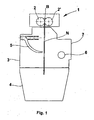
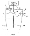
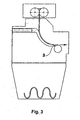
- Figures 1-4 show schematically four successive stages in the operating sequence of a plant according to a preferred aspect of the invention.
- the continuous metallic strip casting plant of Figure 1 comprises an ingot mould 1 which comprises in turn a pair of rolls 2, 2', named also "counter rotating rolls” in the following description.
- the rolls 2, 2' rotate around two axes parallel to each other in opposite rotating directions, the left roll in a clockwise direction and that on the right in anticlockwise direction with reference to the orientation in the figures.
- the rolls 2, 2' are distanced apart so as to be separated at their point of minimal distance, by a slot through which the molten metal bath B exits downwards, cooling it and forming with a continuous casting operation the metallic strip N.
- Reference 3 indicates a chamber filled preferably with inert gasses, to create a controlled atmosphere which avoids oxidation of the metal.
- the metallic strip N is immersed In this chamber from its formation, on exit from the ingot mould.
- the inert chamber 3 Underneath the inert chamber 3 there is placed a chest 4 for wastes inside which crop ends of the strip N are let fall when they are cut immediately -or almost immediately- downstream of the ingot mould 1, as can be seen in more detail in the following.
- the wastes chest 4 receives also the melt still remaining in the ingot mould when the casting operation, for any reason, must be suspended or interrupted, by reciprocal distancing of the counter rotating rolls 2, 2'.
- the inert chamber 3 has a side 7 from which the strip N emerges, continuously cast by the plant.
- various strip processing devices which comprise guide rolls, schematically represented by a single cylinder 6, onto which the strip rests drawn by appropriate devices.
- Figure 2 is a stage of the cast operation in the plant of Figure 1, in which a crop end 10 of metallic strip N has been sliced - or however detached by an appropriate device - from the remainder of the strand N.
- Means for drawing the strip consists in varying shortly the speed of rotation of the rolls 2 in such a way to produce a thinning of the strip N immediately upon exit from the pair of rolls 2, so that the latter tears under its own weight, or the strip can be sliced by other known mechanical devices or other casting procedures.
- This cutting operation is for example necessary upon starting the casting operation, or following an interruption of the casting operation for any reason, to eliminate the initial section of the new strand if this does not have the desired mechanical characteristics, as it often happens.
- the tom crop end 10 can fall by gravity into the underlying wastes chest 3.
- the mobile plate 5 is equipped with motorised means, as for example a hydraulic cylinder, able to impart a translational movement in a substantially horizontal direction to the plate bringing it in interference with the strip N, and deviating the latter from its vertical trajectory under the ingot mould 1. It brings the foremost end
- the conveying means 6 can also comprise means for drawing the strip N towards the other processing stations, for example the rolling, cooling, winding and cutting stations.
- Such means can be one or more pairs of drawing rolls. Initially, however the strip N is pushed forwards by the rotation of the casting rolls 2 and 2', whilst not being engaged by such means.
- the mobile plate or flap 5 has preferably an appropriately arched shape so as to gradually deviate the strip N from an almost vertical direction to the substantially horizontal direction on the rolling pathway 6.
- the mobile flap 5 for most of its upper surface corresponds to the surface of a circular cylinder.
- the mobile flap 5 can be made to interfere with the cast strip N, to deflect it, with a purely translation movement.
- the translation movement occurs according to a substantially horizontal rectilinear trajectory.
- a sheer translation movement especially if horizontal, has the further advantage of reducing the relative frictional velocity between the strip and the flap, in the phase when the movement of the flap occurs towards the position of maximal interference.
- Figure 3 shows the mobile flap 5 upon reaching the end position of its operational course: It is in a position such that the foremost area of the cast strip N has a curvature, obtained by a gradual displacement of the deflector.
- the strip N at this stage is deviated from the initial line of vertical movement, or from the axis of casting, in a progressive manner.
- the leading edge 9 of the flap is found at a height such that the strip N passes from the edge 9 to the roll conveyor 6 without violent or however dangerous curvatures.
- the mobile flap 5 can move from the standby end position to the operative end position by moving along a route not necessarily rectilinear but alternatively curved, or along a rectilinear route not horizontally but inclined, where for example the position of the standby end position is located higher than the position than the operative end point, and the flap approaches the casting strip with a downward movement.
Landscapes
- Engineering & Computer Science (AREA)
- Mechanical Engineering (AREA)
- Metal Rolling (AREA)
- Continuous Casting (AREA)
- Wire Processing (AREA)
- Devices For Conveying Motion By Means Of Endless Flexible Members (AREA)
Claims (3)
- Kontinuierliche Metallstreifengießanlage, umfassend:- eine Kokille (1) mit einem Paar an gegenläufig drehenden Walzen (2, 2'), die so angepasst ist, dass kontinuierlich ein Metallstreifen (N) entlang einer vertikalen Gießrichtung gegossen wird;- Fördermittel (6) dieses Metallstreifens, die stromabwärts dieser Gießrichtung angeordnet sind, die so angepasst sind, dass der Metallstreifen an nachfolgende Verarbeitungsstationen übergeben wird;- eine mobile Ablenkvorrichtung (5), die niedriger als diese gegenläufig drehenden Walzen angeordnet ist und die in der Lage ist, einen Anfangsteil des Metallstreifens abzulenken, wodurch er in Richtung dieser Fördermittel (6) abgeleitet wird, und die zusätzlich so angepasst ist, dass sie von einer Warteposition ohne Wechselwirkung mit diesem Metallstreifen (N) zu einer Arbeitsstellung mit Wechselwirkung mit diesem Metallstreifen (N) übergeht, wobei sie den Anfangsteil des Streifens von der vertikalen Gießrichtung ablenkt, gekennzeichnet durch die Tatsache, dass Motormittel zum Umsetzen dieser mobilen Ablenkvorrichtung (5) entlang eines horizontalen geradlinigen Bewegungsablaufs von der Wartestellung zu der Arbeitsstellung mit Wechselwirkung bereitgestellt werden.
- Anlage nach Anspruch 1, worin diese Ablenkvorrichtung (5) eine gerundete Kante (9) im vordersten Teil in Bezug auf die Gießebene bereitstellt.
- Verfahren zum kontinuierlichen Metallstreifengießen mittels einer Anlage gemäß einem oder mehreren der vorstehenden Ansprüche, umfassend die folgenden Arbeitsgänge:- Gießen eines Anfangsteils eines Metallstreifens mit einer vorbestimmten Länge in einer vertikalen Richtung durch eine Kokille (1) mit gegenläufig drehenden Walzen (2, 2');- Einstellen dieser Ablenkvorrichtung in eine Wechselwirkungsposition mit der vertikalen Streifengießrichtung;- wenn die führende Kante des Streifens anfängt, auf den Oberflächen der Ablenkvorrichtung (5) aufzuliegen und von diesem im Wesentlichen vertikalen Förderpfad abzuweichen, wird die Ablenkvorrichtung (5) in eine horizontale Richtung umgesetzt, um den Pfad der Förderung des Anfangsstreifenteils abzuleiten und ihn dazu zu bringen, eine horizontale geradlinige Bewegungsrichtung anzunehmen;- Annähern an die Führungskante des Streifens durch eine weitere Umsetzung dieser Ablenkrichtung (5) in Richtung von Halte- und/oder Zugvorrichtungen, um die Vorderkante des Streifens zu fassen und sie in Richtung vorbestimmter Verarbeitungsstationen zu ziehen;- Umsetzen dieser Ablenkvorrichtung (5) in eine horizontale Richtung in eine Richtung ihres Entfernens von dem Streifen.
Applications Claiming Priority (3)
| Application Number | Priority Date | Filing Date | Title |
|---|---|---|---|
| ITMI20021509 | 2002-07-10 | ||
| IT2002MI001509A ITMI20021509A1 (it) | 2002-07-10 | 2002-07-10 | Impianto e metodo di colata continua con dispositivo deflettore per nastri metallici |
| PCT/EP2003/007301 WO2004007112A1 (en) | 2002-07-10 | 2003-07-08 | Continuous casting plant with a deflecting device for metallic strips and deflecting method |
Publications (2)
| Publication Number | Publication Date |
|---|---|
| EP1521649A1 EP1521649A1 (de) | 2005-04-13 |
| EP1521649B1 true EP1521649B1 (de) | 2008-01-09 |
Family
ID=11450170
Family Applications (1)
| Application Number | Title | Priority Date | Filing Date |
|---|---|---|---|
| EP03735699A Expired - Lifetime EP1521649B1 (de) | 2002-07-10 | 2003-07-08 | Stranggiessanlage mit ablenkvorrichtung für metallbändern und ablenkverfahren |
Country Status (8)
| Country | Link |
|---|---|
| US (1) | US20050236134A1 (de) |
| EP (1) | EP1521649B1 (de) |
| CN (1) | CN1665619A (de) |
| AT (1) | ATE383213T1 (de) |
| AU (1) | AU2003238068A1 (de) |
| DE (1) | DE60318577D1 (de) |
| IT (1) | ITMI20021509A1 (de) |
| WO (1) | WO2004007112A1 (de) |
Families Citing this family (4)
| Publication number | Priority date | Publication date | Assignee | Title |
|---|---|---|---|---|
| AT412539B (de) * | 2003-05-06 | 2005-04-25 | Voest Alpine Ind Anlagen | Zweiwalzengiesseinrichtung |
| US8826966B1 (en) * | 2009-12-21 | 2014-09-09 | Iowa State University Research Foundation, Inc. | Melt containment member |
| CN102294450A (zh) * | 2010-06-25 | 2011-12-28 | 宝山钢铁股份有限公司 | 一种薄带连铸断带后保持连续浇铸的方法 |
| CN112157232B (zh) * | 2020-09-16 | 2021-10-19 | 东北大学 | 一种多弧度导卫板 |
Family Cites Families (7)
| Publication number | Priority date | Publication date | Assignee | Title |
|---|---|---|---|---|
| GB980420A (en) * | 1963-01-08 | 1965-01-13 | United Steel Companies Ltd | Continuous casting machines |
| BE789204A (fr) * | 1971-10-01 | 1973-03-22 | Uss Eng & Consult | Procede et appareil pour utiliser une barre d'amorcage rigide dans un dispositif de cintrage fixe |
| JPS60221103A (ja) * | 1984-04-17 | 1985-11-05 | Ishikawajima Harima Heavy Ind Co Ltd | 鋳造圧延設備 |
| JP3016645B2 (ja) * | 1991-11-27 | 2000-03-06 | 新日本製鐵株式会社 | 双ロール連続鋳造装置 |
| DE19637545B4 (de) * | 1996-09-14 | 2007-10-18 | Sms Demag Ag | Vorrichtung zur Umleitung eines in einer Stranggießkokille gegossenen Dünnbrammenstranges aus der Vertikalen in eine horizontale Ausförderrichtung |
| AT406026B (de) * | 1998-03-25 | 2000-01-25 | Voest Alpine Ind Anlagen | Stranggiessanlage zum kontinuierlichen giessen eines dünnen bandes sowie verfahren hierzu |
| AUPP964499A0 (en) * | 1999-04-08 | 1999-04-29 | Bhp Steel (Jla) Pty Limited | Casting strip |
-
2002
- 2002-07-10 IT IT2002MI001509A patent/ITMI20021509A1/it unknown
-
2003
- 2003-07-08 DE DE60318577T patent/DE60318577D1/de not_active Expired - Lifetime
- 2003-07-08 US US10/520,765 patent/US20050236134A1/en not_active Abandoned
- 2003-07-08 AU AU2003238068A patent/AU2003238068A1/en not_active Abandoned
- 2003-07-08 EP EP03735699A patent/EP1521649B1/de not_active Expired - Lifetime
- 2003-07-08 CN CN03816054.4A patent/CN1665619A/zh active Pending
- 2003-07-08 WO PCT/EP2003/007301 patent/WO2004007112A1/en not_active Ceased
- 2003-07-08 AT AT03735699T patent/ATE383213T1/de not_active IP Right Cessation
Also Published As
| Publication number | Publication date |
|---|---|
| WO2004007112A1 (en) | 2004-01-22 |
| ATE383213T1 (de) | 2008-01-15 |
| US20050236134A1 (en) | 2005-10-27 |
| ITMI20021509A1 (it) | 2004-01-12 |
| AU2003238068A1 (en) | 2004-02-02 |
| EP1521649A1 (de) | 2005-04-13 |
| DE60318577D1 (de) | 2008-02-21 |
| CN1665619A (zh) | 2005-09-07 |
| ITMI20021509A0 (it) | 2002-07-10 |
Similar Documents
| Publication | Publication Date | Title |
|---|---|---|
| EP0999904B1 (de) | Wickelmaschine für warmgewalztes walzgut wie bänder oder bleche | |
| CN113396022B (zh) | 用于生产带材的设备和方法 | |
| CN104209486A (zh) | 一种镁合金圆坯连续铸造装置及工艺 | |
| KR100879847B1 (ko) | 용융 금속으로부터 압연된 금속 스트립을 연속적으로제조하는 방법 및 장치 | |
| JP2011508678A5 (de) | ||
| US20080196236A1 (en) | Compact Plant for Continuous Production of Bars and/or Profiles | |
| US20050236134A1 (en) | Continuous casting plant with a deflecting device for metallic strips and deflecting method | |
| NO761905L (de) | ||
| KR100616306B1 (ko) | 인발 장치 및 그 인발 장치의 작업 방법 | |
| US3351126A (en) | Casting wheel apparatus | |
| US3447591A (en) | Apparatus for bending a casting having a liquid core | |
| RU2004127595A (ru) | Способ бесконечной прокатки, выполненной в сечении как тонкий сляб, полученной со скоростью разливки металлической заготовки, в частности стальной заготовки, и машина для непрерывной разливки | |
| US3319699A (en) | Apparatus for withdrawing and advancing the casting in a continuous casting machine | |
| WO2009054826A1 (en) | Downender transport table assembly for use in continuous casting plants | |
| CN105307797B (zh) | 连续铸造机及其使用方法 | |
| US20250196210A1 (en) | Apparatus and method for feeding and cutting a metal product | |
| US6305068B1 (en) | Continuous horizontal strip casting installation and method for producing a coilable metal strip | |
| US4182146A (en) | Hot rolling mill | |
| KR101726759B1 (ko) | 설비의 교체 및 수리가 용이한 멘드럴 코일박스 | |
| US7140284B2 (en) | Device for cold cutting elongate members along a longitudinal axis | |
| RU2038916C1 (ru) | Установка непрерывной разливки металлов | |
| JPS6120387B2 (de) | ||
| CN111215589A (zh) | 一种带材连续浇铸方法 | |
| SU109556A1 (ru) | Подъемное устройство дл выдачи длинных слитков из колодца на установках дл непрерывной разливки стали | |
| US20050258213A1 (en) | Method and device for the evacuation of casting wastes |
Legal Events
| Date | Code | Title | Description |
|---|---|---|---|
| PUAI | Public reference made under article 153(3) epc to a published international application that has entered the european phase |
Free format text: ORIGINAL CODE: 0009012 |
|
| 17P | Request for examination filed |
Effective date: 20050208 |
|
| AK | Designated contracting states |
Kind code of ref document: A1 Designated state(s): AT BE BG CH CY CZ DE DK EE ES FI FR GB GR HU IE IT LI LU MC NL PT RO SE SI SK TR |
|
| AX | Request for extension of the european patent |
Extension state: AL LT LV MK |
|
| DAX | Request for extension of the european patent (deleted) | ||
| RIN1 | Information on inventor provided before grant (corrected) |
Inventor name: FAGGIANI, EDI Inventor name: POLONI, ALFREDO Inventor name: KAPAJ, NUREDIN Inventor name: DE LUCA, ANDREA |
|
| GRAP | Despatch of communication of intention to grant a patent |
Free format text: ORIGINAL CODE: EPIDOSNIGR1 |
|
| GRAS | Grant fee paid |
Free format text: ORIGINAL CODE: EPIDOSNIGR3 |
|
| GRAA | (expected) grant |
Free format text: ORIGINAL CODE: 0009210 |
|
| RAP1 | Party data changed (applicant data changed or rights of an application transferred) |
Owner name: DANIELI & C. OFFICINE MECCANICHE S.P.A. |
|
| AK | Designated contracting states |
Kind code of ref document: B1 Designated state(s): AT BE BG CH CY CZ DE DK EE ES FI FR GB GR HU IE IT LI LU MC NL PT RO SE SI SK TR |
|
| REG | Reference to a national code |
Ref country code: GB Ref legal event code: FG4D |
|
| REG | Reference to a national code |
Ref country code: CH Ref legal event code: EP |
|
| REG | Reference to a national code |
Ref country code: IE Ref legal event code: FG4D |
|
| REF | Corresponds to: |
Ref document number: 60318577 Country of ref document: DE Date of ref document: 20080221 Kind code of ref document: P |
|
| PG25 | Lapsed in a contracting state [announced via postgrant information from national office to epo] |
Ref country code: NL Free format text: LAPSE BECAUSE OF FAILURE TO SUBMIT A TRANSLATION OF THE DESCRIPTION OR TO PAY THE FEE WITHIN THE PRESCRIBED TIME-LIMIT Effective date: 20080109 Ref country code: SI Free format text: LAPSE BECAUSE OF FAILURE TO SUBMIT A TRANSLATION OF THE DESCRIPTION OR TO PAY THE FEE WITHIN THE PRESCRIBED TIME-LIMIT Effective date: 20080109 |
|
| NLV1 | Nl: lapsed or annulled due to failure to fulfill the requirements of art. 29p and 29m of the patents act | ||
| PG25 | Lapsed in a contracting state [announced via postgrant information from national office to epo] |
Ref country code: LI Free format text: LAPSE BECAUSE OF FAILURE TO SUBMIT A TRANSLATION OF THE DESCRIPTION OR TO PAY THE FEE WITHIN THE PRESCRIBED TIME-LIMIT Effective date: 20080109 Ref country code: ES Free format text: LAPSE BECAUSE OF FAILURE TO SUBMIT A TRANSLATION OF THE DESCRIPTION OR TO PAY THE FEE WITHIN THE PRESCRIBED TIME-LIMIT Effective date: 20080420 Ref country code: CH Free format text: LAPSE BECAUSE OF FAILURE TO SUBMIT A TRANSLATION OF THE DESCRIPTION OR TO PAY THE FEE WITHIN THE PRESCRIBED TIME-LIMIT Effective date: 20080109 Ref country code: FI Free format text: LAPSE BECAUSE OF FAILURE TO SUBMIT A TRANSLATION OF THE DESCRIPTION OR TO PAY THE FEE WITHIN THE PRESCRIBED TIME-LIMIT Effective date: 20080109 |
|
| REG | Reference to a national code |
Ref country code: CH Ref legal event code: PL |
|
| PG25 | Lapsed in a contracting state [announced via postgrant information from national office to epo] |
Ref country code: AT Free format text: LAPSE BECAUSE OF FAILURE TO SUBMIT A TRANSLATION OF THE DESCRIPTION OR TO PAY THE FEE WITHIN THE PRESCRIBED TIME-LIMIT Effective date: 20080109 Ref country code: BG Free format text: LAPSE BECAUSE OF FAILURE TO SUBMIT A TRANSLATION OF THE DESCRIPTION OR TO PAY THE FEE WITHIN THE PRESCRIBED TIME-LIMIT Effective date: 20080409 |
|
| PG25 | Lapsed in a contracting state [announced via postgrant information from national office to epo] |
Ref country code: BE Free format text: LAPSE BECAUSE OF FAILURE TO SUBMIT A TRANSLATION OF THE DESCRIPTION OR TO PAY THE FEE WITHIN THE PRESCRIBED TIME-LIMIT Effective date: 20080109 Ref country code: PT Free format text: LAPSE BECAUSE OF FAILURE TO SUBMIT A TRANSLATION OF THE DESCRIPTION OR TO PAY THE FEE WITHIN THE PRESCRIBED TIME-LIMIT Effective date: 20080609 |
|
| EN | Fr: translation not filed | ||
| PG25 | Lapsed in a contracting state [announced via postgrant information from national office to epo] |
Ref country code: SE Free format text: LAPSE BECAUSE OF FAILURE TO SUBMIT A TRANSLATION OF THE DESCRIPTION OR TO PAY THE FEE WITHIN THE PRESCRIBED TIME-LIMIT Effective date: 20080409 Ref country code: CZ Free format text: LAPSE BECAUSE OF FAILURE TO SUBMIT A TRANSLATION OF THE DESCRIPTION OR TO PAY THE FEE WITHIN THE PRESCRIBED TIME-LIMIT Effective date: 20080109 Ref country code: DK Free format text: LAPSE BECAUSE OF FAILURE TO SUBMIT A TRANSLATION OF THE DESCRIPTION OR TO PAY THE FEE WITHIN THE PRESCRIBED TIME-LIMIT Effective date: 20080109 Ref country code: SK Free format text: LAPSE BECAUSE OF FAILURE TO SUBMIT A TRANSLATION OF THE DESCRIPTION OR TO PAY THE FEE WITHIN THE PRESCRIBED TIME-LIMIT Effective date: 20080109 |
|
| PLBE | No opposition filed within time limit |
Free format text: ORIGINAL CODE: 0009261 |
|
| STAA | Information on the status of an ep patent application or granted ep patent |
Free format text: STATUS: NO OPPOSITION FILED WITHIN TIME LIMIT |
|
| PG25 | Lapsed in a contracting state [announced via postgrant information from national office to epo] |
Ref country code: RO Free format text: LAPSE BECAUSE OF FAILURE TO SUBMIT A TRANSLATION OF THE DESCRIPTION OR TO PAY THE FEE WITHIN THE PRESCRIBED TIME-LIMIT Effective date: 20080109 |
|
| PGFP | Annual fee paid to national office [announced via postgrant information from national office to epo] |
Ref country code: IT Payment date: 20080729 Year of fee payment: 6 |
|
| 26N | No opposition filed |
Effective date: 20081010 |
|
| PG25 | Lapsed in a contracting state [announced via postgrant information from national office to epo] |
Ref country code: DE Free format text: LAPSE BECAUSE OF FAILURE TO SUBMIT A TRANSLATION OF THE DESCRIPTION OR TO PAY THE FEE WITHIN THE PRESCRIBED TIME-LIMIT Effective date: 20080410 |
|
| GBPC | Gb: european patent ceased through non-payment of renewal fee |
Effective date: 20080708 |
|
| PG25 | Lapsed in a contracting state [announced via postgrant information from national office to epo] |
Ref country code: MC Free format text: LAPSE BECAUSE OF NON-PAYMENT OF DUE FEES Effective date: 20080731 |
|
| PG25 | Lapsed in a contracting state [announced via postgrant information from national office to epo] |
Ref country code: FR Free format text: LAPSE BECAUSE OF FAILURE TO SUBMIT A TRANSLATION OF THE DESCRIPTION OR TO PAY THE FEE WITHIN THE PRESCRIBED TIME-LIMIT Effective date: 20081031 Ref country code: EE Free format text: LAPSE BECAUSE OF FAILURE TO SUBMIT A TRANSLATION OF THE DESCRIPTION OR TO PAY THE FEE WITHIN THE PRESCRIBED TIME-LIMIT Effective date: 20080109 |
|
| PG25 | Lapsed in a contracting state [announced via postgrant information from national office to epo] |
Ref country code: GB Free format text: LAPSE BECAUSE OF NON-PAYMENT OF DUE FEES Effective date: 20080708 |
|
| PG25 | Lapsed in a contracting state [announced via postgrant information from national office to epo] |
Ref country code: CY Free format text: LAPSE BECAUSE OF FAILURE TO SUBMIT A TRANSLATION OF THE DESCRIPTION OR TO PAY THE FEE WITHIN THE PRESCRIBED TIME-LIMIT Effective date: 20080109 Ref country code: IE Free format text: LAPSE BECAUSE OF NON-PAYMENT OF DUE FEES Effective date: 20080708 |
|
| PG25 | Lapsed in a contracting state [announced via postgrant information from national office to epo] |
Ref country code: LU Free format text: LAPSE BECAUSE OF NON-PAYMENT OF DUE FEES Effective date: 20080708 Ref country code: HU Free format text: LAPSE BECAUSE OF FAILURE TO SUBMIT A TRANSLATION OF THE DESCRIPTION OR TO PAY THE FEE WITHIN THE PRESCRIBED TIME-LIMIT Effective date: 20080710 |
|
| PG25 | Lapsed in a contracting state [announced via postgrant information from national office to epo] |
Ref country code: TR Free format text: LAPSE BECAUSE OF FAILURE TO SUBMIT A TRANSLATION OF THE DESCRIPTION OR TO PAY THE FEE WITHIN THE PRESCRIBED TIME-LIMIT Effective date: 20080109 |
|
| PG25 | Lapsed in a contracting state [announced via postgrant information from national office to epo] |
Ref country code: GR Free format text: LAPSE BECAUSE OF FAILURE TO SUBMIT A TRANSLATION OF THE DESCRIPTION OR TO PAY THE FEE WITHIN THE PRESCRIBED TIME-LIMIT Effective date: 20080410 |
|
| PG25 | Lapsed in a contracting state [announced via postgrant information from national office to epo] |
Ref country code: IT Free format text: LAPSE BECAUSE OF NON-PAYMENT OF DUE FEES Effective date: 20090708 |