EP1522427A2 - Système de roulage à plat - Google Patents
Système de roulage à plat Download PDFInfo
- Publication number
- EP1522427A2 EP1522427A2 EP04018971A EP04018971A EP1522427A2 EP 1522427 A2 EP1522427 A2 EP 1522427A2 EP 04018971 A EP04018971 A EP 04018971A EP 04018971 A EP04018971 A EP 04018971A EP 1522427 A2 EP1522427 A2 EP 1522427A2
- Authority
- EP
- European Patent Office
- Prior art keywords
- support
- wheel rim
- tire
- support ring
- circumferential surface
- Prior art date
- Legal status (The legal status is an assumption and is not a legal conclusion. Google has not performed a legal analysis and makes no representation as to the accuracy of the status listed.)
- Withdrawn
Links
- 239000011324 bead Substances 0.000 claims abstract description 53
- 238000006073 displacement reaction Methods 0.000 description 7
- 229920001971 elastomer Polymers 0.000 description 7
- 230000003247 decreasing effect Effects 0.000 description 6
- 230000004048 modification Effects 0.000 description 4
- 238000012986 modification Methods 0.000 description 4
- 239000013536 elastomeric material Substances 0.000 description 3
- 229920002635 polyurethane Polymers 0.000 description 3
- 239000004814 polyurethane Substances 0.000 description 3
- 229920002943 EPDM rubber Polymers 0.000 description 2
- 150000001875 compounds Chemical class 0.000 description 2
- 239000000806 elastomer Substances 0.000 description 2
- 239000000314 lubricant Substances 0.000 description 2
- 230000003014 reinforcing effect Effects 0.000 description 2
- 229910000831 Steel Inorganic materials 0.000 description 1
- 230000001133 acceleration Effects 0.000 description 1
- 230000015556 catabolic process Effects 0.000 description 1
- 238000010276 construction Methods 0.000 description 1
- 238000006731 degradation reaction Methods 0.000 description 1
- 230000020169 heat generation Effects 0.000 description 1
- 238000000034 method Methods 0.000 description 1
- 238000000465 moulding Methods 0.000 description 1
- 230000005855 radiation Effects 0.000 description 1
- 239000010959 steel Substances 0.000 description 1
Images


Classifications
-
- B—PERFORMING OPERATIONS; TRANSPORTING
- B60—VEHICLES IN GENERAL
- B60C—VEHICLE TYRES; TYRE INFLATION; TYRE CHANGING; CONNECTING VALVES TO INFLATABLE ELASTIC BODIES IN GENERAL; DEVICES OR ARRANGEMENTS RELATED TO TYRES
- B60C17/00—Tyres characterised by means enabling restricted operation in damaged or deflated condition; Accessories therefor
- B60C17/04—Tyres characterised by means enabling restricted operation in damaged or deflated condition; Accessories therefor utilising additional non-inflatable supports which become load-supporting in emergency
- B60C17/041—Tyres characterised by means enabling restricted operation in damaged or deflated condition; Accessories therefor utilising additional non-inflatable supports which become load-supporting in emergency characterised by coupling or locking means between rim and support
- B60C17/042—Tyres characterised by means enabling restricted operation in damaged or deflated condition; Accessories therefor utilising additional non-inflatable supports which become load-supporting in emergency characterised by coupling or locking means between rim and support preventing sliding or rotation between support and rim
-
- B—PERFORMING OPERATIONS; TRANSPORTING
- B60—VEHICLES IN GENERAL
- B60C—VEHICLE TYRES; TYRE INFLATION; TYRE CHANGING; CONNECTING VALVES TO INFLATABLE ELASTIC BODIES IN GENERAL; DEVICES OR ARRANGEMENTS RELATED TO TYRES
- B60C17/00—Tyres characterised by means enabling restricted operation in damaged or deflated condition; Accessories therefor
- B60C17/04—Tyres characterised by means enabling restricted operation in damaged or deflated condition; Accessories therefor utilising additional non-inflatable supports which become load-supporting in emergency
- B60C17/06—Tyres characterised by means enabling restricted operation in damaged or deflated condition; Accessories therefor utilising additional non-inflatable supports which become load-supporting in emergency resilient
- B60C17/061—Tyres characterised by means enabling restricted operation in damaged or deflated condition; Accessories therefor utilising additional non-inflatable supports which become load-supporting in emergency resilient comprising lateral openings
Definitions
- the present invention relates to a runflat system comprising a pneumatic tire, wheel rim and support ring disposed in the tire cavity, more particularly to a combination of a wheel rim and support ring improved in the boundary construction therebetween.
- a support ring made of an elastomer disposed in the tire cavity to support a tire load comes into practical use in recent years.
- the support ring is an annular body whose center hole has a smooth surface, and the support ring is press fitted to its seat which is provided on the wheel rim as a smooth surface. The binding force between the support ring and the wheel rim relies on the elastic behavior of the support ring.
- the binding force decreases. If the binding force is decreased, the support ring is rotated relatively to the wheel rim at the time of sudden stop and sudden acceleration in particular. As a result, the wheel is very liable to lose a dynamic balance.
- a primary object of the present invention is to provide a runflat system being capable of preventing the degradation in the dynamic wheel balance, without making the mounting operation difficult.
- Another object of the present invention is to provide a support ring and/or a wheel rim for use in the runflat system, which can increase the binding force or circumferential engaging force between the support ring and the wheel rim, and also which can improve the mounting or fitting of the support ring onto the wheel rim's support-ring seat.
- a combination of: a wheel rim comprising a pair of axially spaced bead seats, and a support-ring seat between the bead seats; and a support ring disposed in a tire cavity and having an inner circumferential surface fitting to the above-mentioned support-ring seat, and an outer circumferential surface contacting with the inside of a tread portion of the tire mounted on the wheel rim when the tire is deflated, is characterized in that one of or alternatively each of the support-ring seat and the inner circumferential surface is provided with an ordered uneven surface for reducing a friction in the axial direction between the inner circumferential surface and the support-ring seat.
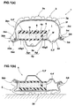
- Fig.1(a) is a cross sectional view of an assembly of a pneumatic tire, wheel rim and support ring according to the present invention, showing such a condition that the tire is normally inflated and no tire load is applied.
- Fig.1(b) is a cross sectional view of the same assembly in the ground contacting patch when a normal tire load is applied and the tire is deflated.
- Fig.2 is a perspective view of the support ring, showing an example provided with an uneven surface in accordance with the present invention.
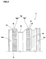
- Fig.3 is an elevational view of an upper half of the wheel rim, showing an example provided with an uneven surface in accordance the present invention.
- Fig.4 is an enlarged schematic cross sectional view showing a combination of a support ring and a wheel rim each provided with uneven surface.
- Fig.5 is an enlarged schematic cross sectional view showing a combination of a support ring provided with uneven surface and a wheel rim not provided with uneven surface.
- Fig.6 is an enlarged schematic cross sectional view showing a combination of a wheel rim provided with uneven surface and a support ring not provided with uneven surface.
- Fig.7 is a perspective view showing another example of the uneven surface for the support ring or wheel rim.
- Fig.7(a) is a perspective view showing a modification thereof.
- Fig.8 is a perspective view showing still another example of the uneven surface for the support ring or wheel rim.
- Fig.8(a) is a perspective view showing a modification thereof.
- Figs.9(a), 9(b) and 9(c) are schematic cross sectional views for explaining the mounting operation of the support ring and tire.
- a runflat system comprises: a wheel rim 3, 3'; a pneumatic tire 2 to be mounted thereon; and a support ring 4, 4' to be disposed in the tire cavity (i) and mounted on the wheel rim.
- Figs.1A and 1B show an assembly 1 of such pneumatic tire, wheel rim and support ring.
- the pneumatic tire 2 comprise: a tread portion 2a with tread edges; a pair of sidewall portions 2bo and 2bi extending radially inwardly from the respective tread edges; a pair of bead portions 2do and 2di at the radial inner ends of the sidewall portions 2bo and 2bi, respectively; a pair of bead cores 2eo and 2ei disposed in the bead portions 2do and 2di, respectively; a carcass 2f comprising at least one ply of radially arranged cords extending between the bead portions 2do and 2di through the tread portion 2a and sidewall portions 2bo and 2bi and secured in the bead portions 2do and 2di by the bead cores 2eo and 2ei; and a tread reinforcing belt 2g disposed radially outside the carcass 2f in the tread portion 2a and comprises at least two cross breaker plies of cords (for example steel cords).
- cords for example
- the tire is a so called tubeless tire, namely, the inner surface of the tire 2 is covered with an air impermeable rubber as a conventional inner liner or a topping rubber layer of the innermost carcass ply.
- the inner diameter of the outer bead portion 2do is smaller than that of the inner bead portion 2di.
- the carcass ply 2f extends to the axially outside of the bead core 2e, passing through radially inside the bead core 2e.
- On the axially outside the bead core 2e it is turned back and then extends to the axially inside of the bead core 2e, passing between the bead core 2e and the above-mentioned axially outwardly extending carcass ply portion. Then, it is terminated on the axially inside of the bead core 2e.
- the bead bottom is tapered axially outwards reversely to that in the conventional tires.
- the wheel rim 3, 3' comprises: a pair of bead seats 3ao and 3ai for the bead portions 2do and 2di, respectively; a seat 3g for the support ring 4 (hereinafter, the support-ring seat 3g) between the bead seats 3ao and 3ai; and a rim well 3d between the bead seat 3ai and support-ring seat 3g. corresponding to the bead portions 2do and 2di having different diameters, the bead seats 3ao and 3ai also have different diameters.
- both of the bead seats 3ao and 3ai are tapered axially outwardly, namely, reversely to the conventional wheel rim.
- the support-ring seat 3g is divided into two parts 3go and 3gi by a deep and wide circumferential groove 3e. The provision of the central groove 3e is not essential.
- the support-ring seat 3g may be an axially continuous single surface.
- the outer diameters Dg1 and Dg2 (generically, "Dg") of the support-ring seat 3go and 3gi, respectively, are the same values.
- the outer diameters Dg is larger than the outer diameter Da measured at the radially outer end of the flange extending radially outwardly and axially outwardly from the axial end of the outer bead seat 3ao.
- a circumferential protrusion 3f is provided at the axial end of the support-ring seat 3g on the inner bead seat 3ai side in order to prevent axial displacement of the support ring 4 mounted on the support-ring seat 3g.
- the support ring 4, 4' comprises: a radially outer annular part 5 defining an outer circumferential surface 4a of the support ring 4 which comes into contact with the inner surface of the tread portion 2a as shown in Fig.1(b) when the tire is deflated; a radially inner annular part 6 defining the inner circumferential surface 4b of the support ring 4 which fits to the support-ring seat 3g of the wheel rim 3, 3'; and a support wall 7 extending continuously in the circumferential direction while bridging between the outer annular part 5 and inner annular part 6.
- the support ring 4, 4' is made of an elastomeric material. It is preferable that the elastomeric material has: a JIS hardness of not less than 80 degrees; a tensibility (EB) of not less than 200 %, preferably more than 250 % but not more than 350 %; and a loss tangent (tan delta) of not more than 0.15, preferably not more than 0.10.
- EB tensibility
- tan delta loss tangent
- various rubber compounds, polyurethane, ethylene propylene diene monomer (EPDM) and the like can be used. More specifically, a rubber compound having a JIS hardness of about 85 degrees, a polyurethane having a JIS hardness of about 95 degrees, and the like can be used for example.
- the radial height H of the support ring 4, 4' is determined such that, under the normally inflated condition of the tire as shown in Fig.1(a), even if the tire 2 is subjected to a tire load of over the maximum tire load, it does not contact with the inside of the tread portion 2. It is thus, preferable that the radial height H is set in a range of from 40 to 60 % of the cross sectional height of the tire cavity under the normally inflated condition.
- the shape of the outer annular part 5 is generally a flat rectangle which is long in the axial direction
- the shape of the inner annular part 6 is also a flat rectangle which is long in the axial direction.
- the inner annular part 6 protrudes in the axial direction from the axial end of the outer annular part 5.
- the inner annular part 6 is wider than the outer annular part 5. The protruding part comes into contact with or very close to the inside of the outer bead portion 2do.
- the inner annular part 6 may be reinforced with circumferentially extending parallel cords or spirally wound cord(s) in case of rubber in particular although in this embodiment such pull-resistant reinforcing elements are not used.
- the support wall 7 comprises: a circumferential wall 7c extending continuously in the circumferential direction; circumferentially-spaced long axial walls 7a extending from one side of the circumferential wall 7c towards an edge of the support ring 4; and circumferentially-spaced short axial walls 7b extending from the other side of the circumferential wall 7c towards the other edge of the support ring 4.
- the circumferential wall 7c is off-centered and extends in a zigzag fashion, and the long and short axial walls 7a and 7b extend substantially straightly from the peaks of zigzag in parallel with the axial direction.
- the support ring 4 is therefore, provided with hollows 9 each opened on one side of the support ring and thereby the openings are staggered.
- each support wall has a thickness of from about 5 mm to about 10 mm.
- the circumferential pitch of the long axial walls 7a and the circumferential pitch of the short axial walls 7b are in a range of about 15 mm to about 25 mm.
- the outer circumferential surface 4a of the support ring 4 in this example is provided with a plurality of circumferentially extending parallel grooves 10 in order to control generation of frictional heat when the outer circumferential surface 4a contacts with the inside of the tread portion 2a, and to promote heat radiation, and further to provide moderate suppleness being capable of following the deformation of the tread portion during runflat operation.
- a lubricant is usually applied between the outer circumferential surface 4a of the support ring 4 and the inside of the tread portion 2a in order to improve the durability of the support ring 4.
- one of or both of the support ring and heel rim are provided with an ordered uneven surface.
- the support ring 4 is provided in the inner circumferential surface 4b with an uneven surface 13 whereas the support ring 4' is not provided.
- the uneven surface 13 is formed by a large number of depressions 12 and resultant protrusions 11 which are formed by the remaining part.
- the depressions 12 in this example are parallel small v-shaped grooves extending from one of the axial edges to the other.
- the circumferential pitch Pa of the depressions 12 or the small grooves is substantially equal to the groove width Gwa.
- the protrusion 11 has a pointed vertex, whereby the depressions 12 and protrusions 11 in a form of serration are formed.
- the groove width Gwa is 0.3 to 3.0 mm; the circumferential pitch Pa is not less than 0.3 mm and not more than 4.0 mm; and the ratio (Gwa/Pa) of the groove width GWa and circumferential pitch Pa is set in a range of 0.2 to 1.0, more preferably 0.4 to 1.
- the wheel rim 3 is provided in the support-ring seat 3g with an uneven surface 15 as shown in Fig.3, whereas the wheel rim 3' is not provided.
- the uneven surface 15 can be formed to accommodate to the above-mentioned uneven surface 13 of the support ring 4 to derive a maximum engaging force therebetween when combined with the support ring 4 (not 4').
- the uneven surface 15 is made up of depressions 17 and protrusions 16 similar to the protrusions 11 and depressions 12 of the support ring 4.
- the depressions 17 are parallel small grooves extending in parallel with the axial direction across the entire axial width of the support-ring seat 3g, namely, the two parts 3go and 3gi in this particular example.
- the grooves are v-shaped in the cross section and are arranged at the circumferential pitch Pb substantially equal to the groove width Gwb.
- the resultant protrusions 16 are thus formed by the remaining part other than the depressions 17.
- the protrusion 16 has a pointed vertex, whereby the depressions 17 and protrusions 16 in a form of serration are formed.
- the groove width Gwb of the depressions 17 and the circumferential pitch Pb of the depressions 17, are determined so that the depressions 17 and protrusions 16 can fit to the protrusions 11 and depressions 12 of the support ring 4.
- the unevenness of the support-ring seat 3g it is not always necessary that the unevenness of the support-ring seat 3g exactly fits to that of the support ring 4.
- the groove width Gwb is set in a range of from 0.3 to 2.0 mm; and the pitch Pb is set in a range of not less than 0.3 mm but not more than 4.0 mm; and further the ratio (Gwb/Pb) of the groove width Gwb and pitch Pb is set in a range of from 0.2 to 1.0, more preferably 0.4 to 1.0.
- the support ring 4 with the uneven surface 13 and the wheel rim 3 with the uneven surface 15 are combined.
- the uneven surface 13 and the uneven surface 15 have substantially same configurations so as to be able to closely contact with each other.
- the difference Dgmax-Dmax and/or the difference Dgmin-Dmin are preferably set in a range of not less than 0.4 mm preferably more that 0.6 mm, but not more than 4.0 mm preferably less than 3.0 mm.
- Dgmax is the maximum outer diameter of the support-ring seat 3g defined at the outer ends (vertexes) of the protrusions 16.
- Dgmin is the minimum outer diameter of the support-ring seat 3g defined at the bottom of the depressions 17.
- Dmax is the maximum inner diameter of the support ring 4 defined at the bottom of the depressions 12.
- Dmin is the minimum inner diameter of the support ring 4 defined at the inner ends (vertexes) of the protrusions 11.
- the difference Dgmax-Dmin (when the outer ends of the protrusions 16 contact with the inner ends of the protrusions 11) or the difference Dgmin-Dmin (when the inner ends of the protrusions 11 reach to the bottom of the depressions 17) or the difference Dgmax-Dmax (the outer ends of the protrusions 16 reach to the bottom of the depressions 12) is set in the above-mentioned range.
- the support ring 4 with the uneven surface 13 can be combined with a wheel rim 3'.
- the wheel rim 3' is the same as the above-mentioned wheel rim 3, excepting that the support-ring seat 3g is not provided with the uneven surface 15 and thus it is a smooth surface.
- the difference Dg-Dmin is set in a range of not less than 0.4 mm preferably more that 0.6 mm, but not more than 4.0 mm preferably less than 3.0 mm.
- Dg is the outer diameter of the support-ring seat 3g of the wheel rim 3'.
- the maximum inner diameter Dmax of the support ring 4 is preferably set to be 0.4 mm to 4.0mm larger than the minimum inner diameter Dmin. More preferably, the difference Dmax-Dmin therebetween is set in range of from 0.6 to 3.0 mm. In other words, the depth of the grooves or depressions 12 is set in a range of not less than 0.4 mm preferably more that 0.6 mm, but not more than 4.0 mm preferably less than 3.0 mm.
- the wheel rim 3 with the uneven surface 15 can be combined with a support ring 4'.
- the support ring 4' is the same as the support ring 4, excepting that the inner circumferential surface 4b is not provided with the uneven surface 13 and thus it is a smooth surface.
- the maximum outer diameter Dgmax of the support-ring seat 3g is preferably set to be 0.4 mm to 4.0 mm larger than the inner diameter D of the support ring 4'. More preferably, the difference Dgmax-D therebetween is set in a range of from 0.6 to 3.0 mm.
- the depth of the grooves or depressions 17 is preferably set in a range of not less than 0.4 mm, more preferably more that 0.6 mm, but not more than 4.0 mm, more preferably less than 3.0 mm.
- the maximum inner diameter Dmax is substantially equal to or smaller than the outer diameter Dg
- the inner diameter D is substantially equal to or smaller than the minimum outer diameter Dgmin.
- the uneven surface 15 of the wheel rim 3 it is also possible to set the maximum outer diameter Dgmax or the minimum outer diameter Dgmin as being substantially equal to the standardized outer diameter Dr of the smooth support-ring seat 3g of the standardized wheel rim 3'.
- the maximum outer diameter Dgmax is set to be 0.4 to 3.0 mm, more preferably 0.5 to 2.5 mm, larger than the standardized outer diameter Dr.
- the minimum diameter Dgmin is preferably set to be 0.4 to 3.0 mm smaller than the above-mentioned standardized outer diameter Dr.
- the standardized outer diameter of the support-ring seat means the values specified in the Michelin PAX runflat system because higher compatibility therewith is sought. Therefore, if compatibility with another system or standard (if applicable, such as ETRTO, JATMA, T&RA or the like) is sought, the standardized outer diameter has to comply with the standard.
- the uneven surfaces 13 and 15 are formed by the v-shaped small grooves having a specific width arranged at a specific circumferential pitch. But, various shapes or configurations can be used in the depressions and also protrusions.
- Fig.7 and Fig.8 show other examples of the uneven surface. These examples are shown as the uneven surfaces 13 for the support ring 4, but it is of course possible to use in the uneven surfaces 15 of the wheel rim 3.
- the depressions 12 in a form of square mesh is formed by a large number of parallel axial grooves and a large number of parallel circumferential grooves, whereby the protrusions 11 of a rectangular parallelepiped are formed.
- Fig.8 shows a modification of the uneven surface 13 shown in Fig.7, wherein the protrusions 11 are formed as hemispherical.
- hemispherical depressions 12 may be provided like the dimples of a golf ball.
- the protrusions are configured such that the frictional force in the axial direction becomes smaller than that in the circumferential direction.
- This can be achieved by changing the aspect ratio of the protrusion in its plan view and/or selectively forming a sharp edge and round edge.
- the axial edge is formed as a sharp edge and the circumferential edge is formed as a round edge as shown in Fig.7(a).
- the protrusion 11 is formed to be long in the axial direction than the circumferential directions.
- v-shaped cross sectional shape u-shaped, square-shaped, semicircular cross sectional shape and the like may be used for the depressions 12 (not only small-groove type depressions but also depressions in the multiple-independent type protrusions).
- a combination of different types of uneven surfaces 13 and 15 can be possible, for example, a combination of a Fig.2 type uneven surface and a Figs,7-8 type uneven surface which are provided on the wheel rim and support ring, respectively, and vice versa. Even in such a combination, as the protrusions and depressions are engaged, the circumferential frictional force is greatly increased, while effectively decreasing the axial frictional force.
- Figs.9(a), 9(b) and 9(c) show the process of mounting the tire 2 and support ring 4, 4' on the wheel rim 3, 3'.
- the support ring is put inside the tire, and into the center holes thereof, the wheel rim is inserted from the outer bead seat 3ao side.
- the outer bead seat 3ao can pass over the support ring 4 without difficulty.
- the inner bead portion 2di can reach to the rim well 3d without difficulty.
- the support ring is set in the mounting portion 3g.
- the outer bead portion 2do passes over the flange of the outer bead seat 3ao by force, and it is seated on the outer bead seat 3ao.
- the inner bead portion 2di is seated on the inner bead seat 3ai, while partially placing the inner bead portion 2di in the rim well 3d to pass over the hump at the axially inner end of the inner bead seat 3ai.
- lubricant is preferably applied to the outer circumferential surface 4a of the support ring and/or the inner surface of the tread portion 2a.
- the binding force between the inner circumferential surface of the support ring and the support-ring seat of the wheel rim was measured at six positions within the part 3gi of the support-ring seat.
- the mean value for the six measuring positions is shown in Tables 1, 2 and 3.
- Skilled workers evaluated the mounting of the support ring when the support ring is fitted to the support-ring seat of the wheel rim by axially sliding the ring to its position.
- the support ring was mounted on the wheel rim, and the wheel rim was rotated at high speed and made a quick stop within a time period of three seconds, and the lowest rotational speed at which a relative circumferential displacement or rotation was caused between the support ring and the support-ring seat by inertia was measured.
- the wheel rim size was 225 ⁇ 460A.
- the support ring size was 80-460(45), namely, the nominal width of the support ring was 80 mm, the nominal diameter was 460 mm, and the radial height was 45 mm.
- the support ring had the basic structure shown in Fig.2 and was made from polyurethane. uneven surfaces 13 and 15 were formed by carving V-shaped small grooves as explained above.
Landscapes
- Engineering & Computer Science (AREA)
- Mechanical Engineering (AREA)
- Tires In General (AREA)
Applications Claiming Priority (2)
| Application Number | Priority Date | Filing Date | Title |
|---|---|---|---|
| JP2003348571A JP3808858B2 (ja) | 2003-10-07 | 2003-10-07 | サポートリング、及びタイヤ組立体 |
| JP2003348571 | 2003-10-07 |
Publications (2)
| Publication Number | Publication Date |
|---|---|
| EP1522427A2 true EP1522427A2 (fr) | 2005-04-13 |
| EP1522427A3 EP1522427A3 (fr) | 2005-05-04 |
Family
ID=34309214
Family Applications (1)
| Application Number | Title | Priority Date | Filing Date |
|---|---|---|---|
| EP04018971A Withdrawn EP1522427A3 (fr) | 2003-10-07 | 2004-08-10 | Système de roulage à plat |
Country Status (4)
| Country | Link |
|---|---|
| US (1) | US7347240B2 (fr) |
| EP (1) | EP1522427A3 (fr) |
| JP (1) | JP3808858B2 (fr) |
| CN (1) | CN100471703C (fr) |
Cited By (7)
| Publication number | Priority date | Publication date | Assignee | Title |
|---|---|---|---|---|
| EP1604840A1 (fr) * | 2004-06-08 | 2005-12-14 | Société de Technologie Michelin | Appui de roulage à plat pour pneumatiques avec cloisons internes et montage amelioré |
| US7047800B2 (en) | 2004-06-10 | 2006-05-23 | Michelin Recherche Et Technique S.A. | Piezoelectric ceramic fibers having metallic cores |
| US7104302B2 (en) | 2004-06-08 | 2006-09-12 | Michelin Recherche Et Technique S.A. | Run-flat support ring with internal fin |
| US7243694B2 (en) | 2003-12-19 | 2007-07-17 | Michelin Recherche Et Technique S. A. | Run-flat support ring with improved mounting features |
| EP1897705A1 (fr) * | 2006-09-12 | 2008-03-12 | Hutchinson | Dispositif de roulage à plat pour véhicule automobile et ensemble monté l'incorporant. |
| WO2011032590A1 (fr) | 2009-09-17 | 2011-03-24 | Otto Fuchs Kg | Roue de véhicule automobile, et procédé de production d'une roue de véhicule automobile |
| WO2013110904A1 (fr) * | 2012-01-26 | 2013-08-01 | Compagnie Plastic Omnium | Bandage de roue et roue pour bac de collecte de dechets |
Families Citing this family (13)
| Publication number | Priority date | Publication date | Assignee | Title |
|---|---|---|---|---|
| FR2910842B1 (fr) * | 2006-12-28 | 2011-03-11 | Michelin Soc Tech | Pneumatique a endurance amelioree vis-a-vis des chocs externes |
| JP5285520B2 (ja) * | 2009-07-02 | 2013-09-11 | 住友ゴム工業株式会社 | ランフラットタイヤ組立体及びそれに用いられるサポートリング |
| CN101722800B (zh) * | 2009-12-04 | 2011-10-26 | 中国兵器工业第五二研究所 | 一种泄气保用轮胎用的内支撑体 |
| WO2012131712A1 (fr) * | 2011-04-01 | 2012-10-04 | Japala Vishweshwarrao | Ensemble de système de roulage à plat statique amélioré |
| CN103722988A (zh) * | 2013-12-24 | 2014-04-16 | 中橡集团曙光橡胶工业研究设计院 | 设置有支撑物的平底轮辋失压续跑轮胎及支撑物的安装方法 |
| US9731548B2 (en) * | 2014-01-15 | 2017-08-15 | Guirong Yang | Wheel rim retainer |
| CN103722989B (zh) * | 2014-01-15 | 2014-11-19 | 杨桂荣 | 一种铰链式爆胎应急支撑装置 |
| WO2015160625A1 (fr) | 2014-04-13 | 2015-10-22 | Bridgestone Americas Tire Operations, Llc | Ailettes de refroidissement de paroi latérale |
| CN105946470B (zh) * | 2016-05-12 | 2019-07-05 | 泰斯福德(北京)科技发展有限公司 | 一种汽车爆胎应急安全装置 |
| US11613143B2 (en) * | 2018-05-23 | 2023-03-28 | Land to Sand Easy Carts, LLC | Wheel for a cart |
| CN109910524A (zh) * | 2018-09-04 | 2019-06-21 | 西安远通耐特汽车安全技术有限公司 | 一种基于轮辋的复合式轮胎安全防护装置 |
| CN111634159B (zh) * | 2020-06-04 | 2024-08-06 | 泰斯福德(北京)科技发展有限公司 | 一种汽车爆胎应急装置 |
| CN115257245A (zh) * | 2022-06-28 | 2022-11-01 | 中国第一汽车股份有限公司 | 一种重载车型用车轮总成及具有该车轮总成的车辆 |
Citations (4)
| Publication number | Priority date | Publication date | Assignee | Title |
|---|---|---|---|---|
| US5361817A (en) | 1993-09-15 | 1994-11-08 | Chen Long Hsiung | Heat-dissipating means of nest tire structure for a run-flat tire |
| JPH07149118A (ja) | 1993-11-30 | 1995-06-13 | Bridgestone Corp | リムと空気入りタイヤ用回転中子の嵌合体に供されるスペーサー |
| US5690762A (en) | 1993-02-10 | 1997-11-25 | Bayerische Moteren Werke Aktiengesellschaft | Emergency ring for a vehicle wheel |
| WO2001032450A1 (fr) | 1999-11-04 | 2001-05-10 | Societe De Technologie Michelin | Appui de securite et ensemble appui et jante pour pneumatique comportant des moyens de centrage et a montage facilite |
Family Cites Families (26)
| Publication number | Priority date | Publication date | Assignee | Title |
|---|---|---|---|---|
| US1949501A (en) * | 1931-05-07 | 1934-03-06 | Morgan & Wright | Tire rim |
| US2427216A (en) * | 1942-06-09 | 1947-09-09 | Gen Tire & Rubber Co | Tire mounting rim |
| US2701971A (en) * | 1950-04-01 | 1955-02-15 | Carter Andrew Gray | Wheel assembly |
| JPS54122501A (en) * | 1978-03-14 | 1979-09-22 | Ohtsu Tire & Rubber Co Ltd | Safe wheel |
| DE3148313C2 (de) * | 1981-12-07 | 1983-11-03 | Paul Vom Stein & Co, 5632 Wermelskirchen | Laufrolle für Apparate, Möbel od. dgl. |
| DE8405217U1 (de) * | 1984-02-21 | 1985-05-30 | Uniroyal Englebert Reifen GmbH, 5100 Aachen | Fahrzeugrad |
| CH668396A5 (de) | 1985-10-21 | 1988-12-30 | Fischer Ag Georg | Sicherheitsfahrzeugrad. |
| US4923252A (en) * | 1988-06-01 | 1990-05-08 | Mtd Products, Inc. | Tire assembly |
| EP0356798B1 (fr) * | 1988-08-12 | 1993-12-29 | Bando Chemical Industries, Limited | Transmission à courroie et poulie |
| GB8926878D0 (en) * | 1989-11-28 | 1990-01-17 | Houghton Adrian K | Run flat tyres,inserts and wheels |
| DE9206460U1 (de) | 1992-05-13 | 1992-09-17 | Marx, Klaus, 5300 Bonn | Kraftfahrzeugrad mit Pannenlaufeigenschaften für schlauchlose Radialgürtelreifen |
| US5313994A (en) * | 1992-05-15 | 1994-05-24 | Southeast Tire Company | Solid rubber wheel and tire assembly with angled cross bars |
| FR2699121B1 (fr) | 1992-12-11 | 1995-03-17 | Michelin & Cie | Ensemble formé d'un pneumatique, d'une jante et d'un anneau de soutien. |
| US5542752A (en) * | 1993-03-05 | 1996-08-06 | Quaglia; Lawrence D. | Wheel product comprised of a new wheel tread lock and a new wheel tread material |
| FR2716645B1 (fr) | 1994-02-28 | 1996-04-19 | Michelin & Cie | Pneumatique avec des bourrelets de structure améliorée et ensemble d'un tel pneumatique avec une jante adaptée. |
| US5630891A (en) * | 1994-12-12 | 1997-05-20 | The Hyper Corporation | Pneumatic in-line skate wheel |
| FR2746347A1 (fr) | 1996-03-19 | 1997-09-26 | Michelin & Cie | Appui de securite en materiau elastomerique souple pour pneumatique |
| FR2748695B1 (fr) * | 1996-05-15 | 1998-06-26 | Michelin & Cie | Roue avec jante ayant des sieges inclines vers l'exterieur |
| FR2781184A1 (fr) * | 1998-07-20 | 2000-01-21 | Michelin Rech Tech | Roue avec jante ayant des sieges inclines vers l'exterieur |
| FR2794686B1 (fr) * | 1999-06-10 | 2001-08-10 | Michelin Soc Tech | Appui de securite allege pour pneumatique |
| US6598633B1 (en) * | 1999-11-04 | 2003-07-29 | Michelin Recherche Et Technique S.A. | Tire safety support and rim and support assembly containing centering means and with facilitated mounting |
| FR2800671A1 (fr) | 1999-11-04 | 2001-05-11 | Michelin Soc Tech | Jante destinee a recevoir un anneau de soutien |
| FR2803595A1 (fr) * | 2000-01-12 | 2001-07-13 | Michelin Soc Tech | Composition de caoutchouc utilisable a l'etat vulcanise comme appui de securite pour pneumatique et un tel appui |
| US6478387B1 (en) * | 2001-07-13 | 2002-11-12 | The Goodyear Tire & Rubber Company | Heavy duty dual tire assembly |
| US6814114B2 (en) * | 2001-11-26 | 2004-11-09 | Michelin Recherche Et Technique S.A. | Tire to rim rotation limiter for a run-flat assembly |
| US20050072504A1 (en) * | 2003-03-31 | 2005-04-07 | White John Richard | Tire support ring reinforcement |
-
2003
- 2003-10-07 JP JP2003348571A patent/JP3808858B2/ja not_active Expired - Fee Related
-
2004
- 2004-08-06 US US10/912,190 patent/US7347240B2/en not_active Expired - Fee Related
- 2004-08-10 EP EP04018971A patent/EP1522427A3/fr not_active Withdrawn
- 2004-09-20 CN CNB2004100780832A patent/CN100471703C/zh not_active Expired - Fee Related
Patent Citations (4)
| Publication number | Priority date | Publication date | Assignee | Title |
|---|---|---|---|---|
| US5690762A (en) | 1993-02-10 | 1997-11-25 | Bayerische Moteren Werke Aktiengesellschaft | Emergency ring for a vehicle wheel |
| US5361817A (en) | 1993-09-15 | 1994-11-08 | Chen Long Hsiung | Heat-dissipating means of nest tire structure for a run-flat tire |
| JPH07149118A (ja) | 1993-11-30 | 1995-06-13 | Bridgestone Corp | リムと空気入りタイヤ用回転中子の嵌合体に供されるスペーサー |
| WO2001032450A1 (fr) | 1999-11-04 | 2001-05-10 | Societe De Technologie Michelin | Appui de securite et ensemble appui et jante pour pneumatique comportant des moyens de centrage et a montage facilite |
Cited By (13)
| Publication number | Priority date | Publication date | Assignee | Title |
|---|---|---|---|---|
| US7243694B2 (en) | 2003-12-19 | 2007-07-17 | Michelin Recherche Et Technique S. A. | Run-flat support ring with improved mounting features |
| EP1604840A1 (fr) * | 2004-06-08 | 2005-12-14 | Société de Technologie Michelin | Appui de roulage à plat pour pneumatiques avec cloisons internes et montage amelioré |
| US7104302B2 (en) | 2004-06-08 | 2006-09-12 | Michelin Recherche Et Technique S.A. | Run-flat support ring with internal fin |
| US7047800B2 (en) | 2004-06-10 | 2006-05-23 | Michelin Recherche Et Technique S.A. | Piezoelectric ceramic fibers having metallic cores |
| EP1900551A1 (fr) * | 2006-09-12 | 2008-03-19 | Hutchinson | Dispositif de roulage à plat pour véhicule automobile et ensemble monté l'incorporant |
| FR2905631A1 (fr) * | 2006-09-12 | 2008-03-14 | Hutchinson Sa | Dispositif de roulage a plat pour vehicule automobile et ensemble monte l'incorporant. |
| EP1897705A1 (fr) * | 2006-09-12 | 2008-03-12 | Hutchinson | Dispositif de roulage à plat pour véhicule automobile et ensemble monté l'incorporant. |
| US7918255B2 (en) | 2006-09-12 | 2011-04-05 | Hutchinson | Run flat device for a motor vehicle, and a wheel assembly incorporating it |
| US7946324B2 (en) | 2006-09-12 | 2011-05-24 | Hutchinson | Run flat device for a motor vehicle, and a wheel assembly incorporating it |
| WO2011032590A1 (fr) | 2009-09-17 | 2011-03-24 | Otto Fuchs Kg | Roue de véhicule automobile, et procédé de production d'une roue de véhicule automobile |
| WO2013110904A1 (fr) * | 2012-01-26 | 2013-08-01 | Compagnie Plastic Omnium | Bandage de roue et roue pour bac de collecte de dechets |
| FR2986184A1 (fr) * | 2012-01-26 | 2013-08-02 | Plastic Omnium Cie | Bandage de roue et roue pour bac de collecte de dechets |
| CN104066594A (zh) * | 2012-01-26 | 2014-09-24 | 全耐塑料公司 | 用于废物收集箱的轮胎和轮子 |
Also Published As
| Publication number | Publication date |
|---|---|
| CN1605483A (zh) | 2005-04-13 |
| US7347240B2 (en) | 2008-03-25 |
| JP3808858B2 (ja) | 2006-08-16 |
| JP2005112137A (ja) | 2005-04-28 |
| EP1522427A3 (fr) | 2005-05-04 |
| US20050072506A1 (en) | 2005-04-07 |
| CN100471703C (zh) | 2009-03-25 |
Similar Documents
| Publication | Publication Date | Title |
|---|---|---|
| US7347240B2 (en) | Runflat system | |
| US6789591B2 (en) | Pneumatic tire | |
| EP0314445B1 (fr) | Pneumatique de sécurité | |
| EP0726174B1 (fr) | Pneumatique et méthode pour sa fabrication | |
| KR100303666B1 (ko) | 가황처리된레이디얼플라이공기타이어 | |
| EP0527597B1 (fr) | Bandage pneumatique | |
| US4977942A (en) | Pneumatic tire having defined lug groove configuration | |
| JPS595444B2 (ja) | 空気安全タイヤ− | |
| JP3568321B2 (ja) | 空気入りタイヤ及びそのタイヤ成形用金型 | |
| US6321806B1 (en) | Pneumatic tire with rim flange holder | |
| EP0652120B1 (fr) | Bandage pneumatique radial amélioré | |
| US5373884A (en) | Pneumatic tires with spaced sidewall recesses | |
| EP1486356B1 (fr) | Anneau de support de sécurité pour pneumatiques et ensemmble jante-roue | |
| US4057092A (en) | Pneumatic tire for use when deflated | |
| US4209051A (en) | Tire having beads with air relief means | |
| EP1294582B1 (fr) | Pneus zero pression | |
| EP0413574B1 (fr) | Pneumatique radial pour grandes vitesses | |
| US20050061410A1 (en) | Pneumatic vehicle tire | |
| JP2005297954A (ja) | 空気入りランフラットタイヤ | |
| JP4257713B2 (ja) | 重荷重用空気入りラジアルタイヤ | |
| CN101301845B (zh) | 漏气保用轮胎 | |
| US7201197B2 (en) | Tire/wheel assembly | |
| JPH01247202A (ja) | 空気タイヤ車輪 | |
| EP4249290B1 (fr) | Pneumatique | |
| US20050167018A1 (en) | Runflat tire system and support ring therefor |
Legal Events
| Date | Code | Title | Description |
|---|---|---|---|
| PUAI | Public reference made under article 153(3) epc to a published international application that has entered the european phase |
Free format text: ORIGINAL CODE: 0009012 |
|
| PUAL | Search report despatched |
Free format text: ORIGINAL CODE: 0009013 |
|
| AK | Designated contracting states |
Kind code of ref document: A2 Designated state(s): AT BE BG CH CY CZ DE DK EE ES FI FR GB GR HU IE IT LI LU MC NL PL PT RO SE SI SK TR |
|
| AX | Request for extension of the european patent |
Extension state: AL HR LT LV MK |
|
| RIC1 | Information provided on ipc code assigned before grant |
Ipc: 7B 60B 21/02 B Ipc: 7B 60C 17/06 B Ipc: 7B 60C 17/04 A |
|
| AK | Designated contracting states |
Kind code of ref document: A3 Designated state(s): AT BE BG CH CY CZ DE DK EE ES FI FR GB GR HU IE IT LI LU MC NL PL PT RO SE SI SK TR |
|
| AX | Request for extension of the european patent |
Extension state: AL HR LT LV MK |
|
| 17P | Request for examination filed |
Effective date: 20051019 |
|
| AKX | Designation fees paid |
Designated state(s): DE FR GB |
|
| 17Q | First examination report despatched |
Effective date: 20061025 |
|
| STAA | Information on the status of an ep patent application or granted ep patent |
Free format text: STATUS: THE APPLICATION IS DEEMED TO BE WITHDRAWN |
|
| 18D | Application deemed to be withdrawn |
Effective date: 20110301 |