EP1522457A2 - Dispositif pour ajuster automatiquement l'orientation d'un projecteur de véhicule - Google Patents
Dispositif pour ajuster automatiquement l'orientation d'un projecteur de véhicule Download PDFInfo
- Publication number
- EP1522457A2 EP1522457A2 EP04024178A EP04024178A EP1522457A2 EP 1522457 A2 EP1522457 A2 EP 1522457A2 EP 04024178 A EP04024178 A EP 04024178A EP 04024178 A EP04024178 A EP 04024178A EP 1522457 A2 EP1522457 A2 EP 1522457A2
- Authority
- EP
- European Patent Office
- Prior art keywords
- steering angle
- light axis
- swivel control
- abnormality
- vehicle
- Prior art date
- Legal status (The legal status is an assumption and is not a legal conclusion. Google has not performed a legal analysis and makes no representation as to the accuracy of the status listed.)
- Granted
Links
Images


Classifications
-
- B—PERFORMING OPERATIONS; TRANSPORTING
- B60—VEHICLES IN GENERAL
- B60Q—ARRANGEMENT OF SIGNALLING OR LIGHTING DEVICES, THE MOUNTING OR SUPPORTING THEREOF OR CIRCUITS THEREFOR, FOR VEHICLES IN GENERAL
- B60Q1/00—Arrangement of optical signalling or lighting devices, the mounting or supporting thereof or circuits therefor
- B60Q1/02—Arrangement of optical signalling or lighting devices, the mounting or supporting thereof or circuits therefor the devices being primarily intended to illuminate the way ahead or to illuminate other areas of way or environments
- B60Q1/04—Arrangement of optical signalling or lighting devices, the mounting or supporting thereof or circuits therefor the devices being primarily intended to illuminate the way ahead or to illuminate other areas of way or environments the devices being headlights
- B60Q1/06—Arrangement of optical signalling or lighting devices, the mounting or supporting thereof or circuits therefor the devices being primarily intended to illuminate the way ahead or to illuminate other areas of way or environments the devices being headlights adjustable, e.g. remotely-controlled from inside vehicle
- B60Q1/08—Arrangement of optical signalling or lighting devices, the mounting or supporting thereof or circuits therefor the devices being primarily intended to illuminate the way ahead or to illuminate other areas of way or environments the devices being headlights adjustable, e.g. remotely-controlled from inside vehicle automatically
- B60Q1/12—Arrangement of optical signalling or lighting devices, the mounting or supporting thereof or circuits therefor the devices being primarily intended to illuminate the way ahead or to illuminate other areas of way or environments the devices being headlights adjustable, e.g. remotely-controlled from inside vehicle automatically due to steering position
-
- B—PERFORMING OPERATIONS; TRANSPORTING
- B60—VEHICLES IN GENERAL
- B60Q—ARRANGEMENT OF SIGNALLING OR LIGHTING DEVICES, THE MOUNTING OR SUPPORTING THEREOF OR CIRCUITS THEREFOR, FOR VEHICLES IN GENERAL
- B60Q11/00—Arrangement of monitoring devices for devices provided for in groups B60Q1/00 - B60Q9/00
-
- B—PERFORMING OPERATIONS; TRANSPORTING
- B60—VEHICLES IN GENERAL
- B60Q—ARRANGEMENT OF SIGNALLING OR LIGHTING DEVICES, THE MOUNTING OR SUPPORTING THEREOF OR CIRCUITS THEREFOR, FOR VEHICLES IN GENERAL
- B60Q2300/00—Indexing codes for automatically adjustable headlamps or automatically dimmable headlamps
- B60Q2300/10—Indexing codes relating to particular vehicle conditions
- B60Q2300/11—Linear movements of the vehicle
- B60Q2300/112—Vehicle speed
-
- B—PERFORMING OPERATIONS; TRANSPORTING
- B60—VEHICLES IN GENERAL
- B60Q—ARRANGEMENT OF SIGNALLING OR LIGHTING DEVICES, THE MOUNTING OR SUPPORTING THEREOF OR CIRCUITS THEREFOR, FOR VEHICLES IN GENERAL
- B60Q2300/00—Indexing codes for automatically adjustable headlamps or automatically dimmable headlamps
- B60Q2300/10—Indexing codes relating to particular vehicle conditions
- B60Q2300/12—Steering parameters
- B60Q2300/122—Steering angle
-
- B—PERFORMING OPERATIONS; TRANSPORTING
- B60—VEHICLES IN GENERAL
- B60Q—ARRANGEMENT OF SIGNALLING OR LIGHTING DEVICES, THE MOUNTING OR SUPPORTING THEREOF OR CIRCUITS THEREFOR, FOR VEHICLES IN GENERAL
- B60Q2300/00—Indexing codes for automatically adjustable headlamps or automatically dimmable headlamps
- B60Q2300/10—Indexing codes relating to particular vehicle conditions
- B60Q2300/12—Steering parameters
- B60Q2300/128—Steering dead zone
-
- B—PERFORMING OPERATIONS; TRANSPORTING
- B60—VEHICLES IN GENERAL
- B60Q—ARRANGEMENT OF SIGNALLING OR LIGHTING DEVICES, THE MOUNTING OR SUPPORTING THEREOF OR CIRCUITS THEREFOR, FOR VEHICLES IN GENERAL
- B60Q2300/00—Indexing codes for automatically adjustable headlamps or automatically dimmable headlamps
- B60Q2300/10—Indexing codes relating to particular vehicle conditions
- B60Q2300/13—Attitude of the vehicle body
- B60Q2300/132—Pitch
-
- B—PERFORMING OPERATIONS; TRANSPORTING
- B60—VEHICLES IN GENERAL
- B60Q—ARRANGEMENT OF SIGNALLING OR LIGHTING DEVICES, THE MOUNTING OR SUPPORTING THEREOF OR CIRCUITS THEREFOR, FOR VEHICLES IN GENERAL
- B60Q2300/00—Indexing codes for automatically adjustable headlamps or automatically dimmable headlamps
- B60Q2300/10—Indexing codes relating to particular vehicle conditions
- B60Q2300/14—Other vehicle conditions
- B60Q2300/146—Abnormalities, e.g. fail-safe
Definitions
- the present invention relates to an apparatus for automatically adjusting a light axis or a lighting area of a light beam emitted from a vehicle headlight on the basis of a steering angle of a steering wheel.
- An apparatus for automatically adjusting directions of light axes of vehicle headlights is constituted by actuators for swiveling horizontally or vertically the vehicle headlights, an ECU (Electronic Control Unit) calculating swiveling or leveling angles of the vehicle headlights based on the signals received from the sensors mounted on the vehicle for detecting the attitude or state of the vehicle such as a steering angle sensor, vehicle height sensors, and a vehicle speed sensor.
- Such an apparatus has to be provided with fail-safe protection mechanism against failure or abnormality in theses sensors or a communication network, for example, a CAN (Controller Area Network) within the vehicle in order to enable returning the light axes of the vehicle headlights to the initial direction or straight forward direction, or lighting an alarm lamp when the failure or abnormality occurs.
- a CAN Controller Area Network
- Japanese Utility Model Application Laid-Open No. 6-42409 discloses a technique for directing forcibly the light axes of the vehicle headlights straight forward in response to the driver's manipulation of a specific manual switch when the steering angle sensor develops trouble.
- This fail-safe action causes an abrupt shift of the lighting area of the vehicle headlights from the swivel-controlled position represented by the dotted line to the straight forward position represented by the solid line. Since the direction of this shift is opposite to the turning direction of the vehicle, the driver feels odd and the visibility in the forward direction becomes worse. In addition, if the steering angle sensor is restored, the position of the lighting area of the vehicle headlights may shift abruptly again, because the swivel control on the light axes of the vehicle headlights resumes promptly after the restoration of the steering angle sensor. The drive feels odd also then.
- the apparatus for automatically adjusting horizontally a direction of a light axis of a headlight of a vehicle of the present invention has a structure including:
- the fail-safe action achieved by this structure makes it possible to avoid the driver of the vehicle from feeling odd to the movements of the light axes of the headlights and to avoid the lowering of visibility in the forward direction when system abnormality has occurred while the vehicle is turning.
- the swivel control unit may continue to adjust the direction of the light axis on the basis of the steering angle signal until the light axis of the headlight is returned to the predetermined initial direction.
- the swivel control unit may adjust horizontally the direction of the light axis such that the light axis is returned gradually to the predetermined initial direction.
- the swivel control unit may resume the swivel control when the abnormality detecting unit detects recovery from the abnormality after the steering angle detected by the steering angle sensor enters into a predetermined angular range within which the vehicle is assumed to be in a straight-running state.
- the swivel control unit may return the light axis of the vehicle headlight from the swiveled-controlled direction to the predetermined direction at a rate of 5 to 30 (preferably 10 to 20) degrees/sec when the abnormality detecting unit detects the abnormality.
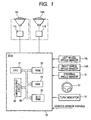
- Fig. 1 shows an overall structure of an apparatus for automatically adjusting a direction of a light axis of a vehicle headlight according to an embodiment of the invention.
- 10L and 10R denote left and right vehicle headlights, respectively.
- the headlights 10L and 10R are linked to actuators 11L and 11R for adjusting the light axes of the headlights 10L and 10R in the horizontal direction.
- An ECU (Electronic Control Unit) 20 includes a CPU 21 for executing various processings, a ROM 22 for storing control programs, control maps, etc., a RAM 23 for temporarily storing various data, a B/U (Back Up) RAM 24, an input-output circuit 25, and a bus line 26 for connecting these elements.
- the ECU 20 receives an output signal from a left wheel speed sensor 16L detecting a left wheel speed VL, an output signal from a right wheel speed sensor 16R detecting a right wheel speed VR, an output signal from a steering angle sensor 18 detecting a steering angle ⁇ of a steering wheel 17, and various sensor signals from other sensors, not illustrated.
- the actuators 11L and 11R act to adjust horizontally the directions of the light axes of the headlights 10L and 10R in accordance with signals outputted from the ECU 20.
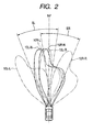
- Fig. 2 shows beam patterns of the headlight 10R and 10L (low beam).
- the heavy solid line 10L-N represents a beam pattern of the headlight 10L when the steering wheel is in its neutral angular position.
- the arched arrow SL represents a swivel range within which the light axis of the headlight 10L can be swiveled in accordance with the steering angle of the steering wheel.
- the chain double-dashed lines 10L-R and 10L-L represent beam patterns of the headlight 10L when the light axis of the headlight 10L is in the rightmost position and the leftmost position within the swivel range, respectively.
- the heavy solid line 10R-N represents a beam pattern of the headlight 10R when the steering wheel is in the neutral angular position.
- the arched arrow SR represents a swivel range within which the light axis of the headlight 10R can be swiveled in accordance with the steering angle of the steering wheel.
- the chain double-dashed lines 10R-R and 10R-L represent beam patterns of the headlight 10R when the light axis of the headlight 10R is in the rightmost position and the leftmost position within the swivel range, respectively.
- the swivel ranges SL and SR should provide the driver with good visibility in the leftward or rightward direction when the driver turns the steering wheel to the left or right without a sacrifice of visibility in the forward direction. Accordingly, as shown in Fig. 2, a portion of the swivel range SR at the right of the initial angular position is wider than that of the swivel range SL so that the variation of the light axis of the headlight 10R is larger than that of the headlight 10L when the driver turns the steering wheel to the right.
- a portion of the swivel range SL at the left of the initial angular position is wider than that of the swivel range SR so that the variation of the light axis of the headlight 10L is larger than that of the headlight 10R when the driver turns the steering wheel to the left.
- Fig. 3 is a diagram showing a signal flow in executing the swivel control when the steering angle sensor 18 is functioning normally, and the output signal of the steering angle sensor 18 is still received normally after abnormality has occurred.
- the steering angle sensor 18 outputs a signal depending on a steering angle of the steering wheel 17. This output signal is subjected to a steering angle detection process P1 to produce a steering angle signal.
- This steering angle signal is subjected to a steering angle calculation process P2 to calculate a steering angle ⁇ .
- This steering angle ⁇ is subjected to a steering angle filtering process P3 in which a filter F (not sown) is used.
- the filtered steering angle ⁇ F is subjected to a primary swiveling angle calculation process P4 to calculate a primary swiveling angle SWc.
- This primary swiveling angle SWc is subjected to a target swiveling angle filtering process P5 in which a filter FSW (not shown) is used to generate a target swiveling angle SWT.
- This target swiveling angle SWT is supplied to a light axis control process P6 for causing the actuators 11L, 11R to adjust horizontally the directions of the light axes of the headlights 10L, 10R.
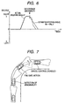
- Fig. 4 illustrates a vehicle making a right turn, the directions of the light axes of the headlights 10L, 10R of this vehicle being controlled by the CPU 21 within the ECU 20 performing the processings shown in the diagram of Fig. 3 on the output signal of the steering angle sensor 18.
- a system abnormality not originating from the steering angle sensor 18 has occurred while the steering wheel 17 of this vehicle is turned to the right.
- an abnormality detecting unit (not illustrated) constituted by the ECU 20
- the directions of the light axes of the headlights 10L, 10R are still controlled horizontally on the basis of the output signal of the steering angle sensor 18, and accordingly, they are still well adjusted to the right-turning road.
- the swivel control on the directions of the light axes of the headlights 10L, 10R is continued as long as the output signal of steering angle sensor 18 is effective.
- the swivel control is disabled.
- the system abnormality has occurred while the vehicle is turning, the light axes of the headlights 10L, 10R are not returned to the straight forward direction immediately. Accordingly, it becomes possible to avoid the driver from feeling odd to the movements of the light axes of the headlights and to avoid the lowering of visibility in the forward direction.
- the swivel control is disabled immediately, because the light axes of the headlights 10L, 10R are directed straight forward at that moment.
- the apparatus for automatically adjusting horizontally a direction of a light axis of a headlight of a vehicle has a structure including:
- the swivel control unit continues performing the swivel control until the light axes of the headlights are returned to the straight forward or initial direction in order to avoid abrupt change of the directions of the light axes of the headlights.
- the swivel control unit halts the swivel control after the light axes of the headlights are returned to the predetermined initial direction.
- the directions of the light axes of the headlights 10L, 10R are swivel-controlled depending on the steering angle ⁇ even after a system abnormality has occurred, if the steering angle sensor 18 is not responsible for the system abnormality and the steering angle ⁇ is still detected normally from the output signal of the steering angle sensor 18.
- the swivel control is disabled when the light axes of the headlights 10L, 10R are returned to the straight forward direction.
- the fail-safe action of this embodiment is characterized in that, when system abnormality has occurred, the light axes of the headlights 10L, 10R are not immediately returned to the straight forward direction but are continued to be swivel-controlled in accordance with the steering angle ⁇ of the steering wheel 17, and fixed at the straight forward direction when they are returned thereto. Thereafter the swivel control is disabled.
- This fail-safe action makes it possible to avoid the driver from feeling odd to the movements of the light axes of the headlights when a system abnormality has occurred while the vehicle is turning.
- Fig. 5 is a diagram showing a signal flow in executing the swivel control when the output signal from the steering angle sensor 18 is discontinued.
- the abnormality detecting unit constituted by the ECU 20 In the graph of Fig. 6, the heavy solid line represents a progression of the actual steering angle ⁇ over time when the vehicle turns right as shown in Fig. 5. If the abnormality occurs while the vehicle is turning right, it becomes impossible from this moment to detect the actual steering angle ⁇ changing along the broken line shown in Fig. 6. Therefore, an estimated steering angle ⁇ e changing smoothly from the value of the last normally detected steering angle to zero degrees as indicated by the thin solid line in Fig.
- this estimated steering angle ⁇ e is subjected to the steering angle filtering process P3 using the filter F (not illustrated) to generate the filtered steering angle ⁇ F.
- the filtered steering angle ⁇ F is subjected to the primary swiveling angle calculation process P4 to calculate the primary swiveling angle SWC as in the case of the steering angle being detected normally on the basis of the output of the steering angle sensor 18.
- the primary swiveling angle SWc is subjected to the target swiveling angle filtering process P5 in which the filter FSW (not illustrated) is used to generate the target swiveling angle SWT.
- the target swiveling angle SWT is supplied to the light axis control process P6 for causing the actuators 11L, 11R to adjust horizontally the directions of the light axes of the headlights 10L, 10R.
- the swivel control is disabled.
- the swivel control is continued on the basis of the estimated steering angle ⁇ e to adjust the directions of the light axes of the headlights 10L, 10R. And when they are directed straight forward (initial direction), the swivel control is disabled.
- the light axes of the headlights 10L, 10R are not returned abruptly to the straight forward direction when the system abnormality has occurred while the vehicle is turning, and so it becomes possible to avoid the driver from feeling odd to the movements of the light axes of the headlights and to avoid the lowering of visibility in the forward direction.
- the swivel control is disabled immediately, because the light axes of the headlights 10L, 10R are directed straight forward at that moment.
- the swivel control unit constituted by the ECU 20 and the actuators 11L, 11R may be configured to continue the swivel control in different ways depending on kinds of abnormality occurred. More specifically, the swivel control unit may be configured to adjust the directions of the light axes of the headlights 10L, 10R in accordance with the detected steering angle ⁇ if the steering angle ⁇ is still detected normally, or to return gradually the light axes of the headlights 10L, 10R from the swivel-controlled directions just before the occurrence of the abnormality toward the straight forward direction and fix them at the straight forward direction when they are returned thereto if the steering angle ⁇ is no more detected normally.
- This fail-safe action of this configuration also makes it possible to avoid the driver from feeling odd to the movements of the light axes of the headlights when system abnormality has occurred while the vehicle is turning.
- the swivel control unit constituted by the ECU 20 and the actuators 11L, 11R is configured to resume the swivel control upon detection of recovery from the abnormality only after the steering angle ⁇ enters into a predetermined angular range within which the vehicle is assumed to be in a straight-running state.
- Such an angular range may be a range extending from +10 degrees through the neutral angular position (0 degrees) to -10 degrees.
- the swivel control is not resumed immediately.
- the swivel control is resumed only after the vehicle goes into the straight-running state. Therefore, the directions of the light axes of the headlights 10L, 10R are not returned abruptly to the straight forward direction when the abnormality has been removed while the vehicle is turning, and so it becomes possible to avoid the driver from feeling odd to the movements of the light axes of the headlights.
- the swivel control unit constituted by the ECU 20 and the actuators 11L, 11R may be configured to return the light axes of the headlights 10L, 10R to the straight forward direction or initial direction at a rate of 5 to 30 degrees/sec, preferably 10 to 20 degrees/sec upon detection of the abnormality.
- the rate at which the light axes of the headlights 10L, 10R are returned to the straight forward direction or initial direction upon detection of the abnormality may be constant, or varied according to the vehicle speed. Alternatively, it may be set at a value specific to the vehicle speed range to which the current vehicle speed belongs. For example, the light axes of the headlights 10L, 10R may be returned to the straight forward direction at a rate of 10 degrees/sec when the vehicle speed is within a lower speed range below 30 km/sec, or at a rate of 20 degrees/sec when the vehicle speed is within a higher speed range equal to or higher than 30 km/sec. It is also possible to return the light axes of the headlights 10L, 10R to the straight forward direction at a rate increasing from 5 degrees/sec to 30 degrees/sec with the increasing vehicle speed.
- a software program for executing the whole of the above-described swivel control in the above-described embodiment can be contained in one module. Accordingly, any specific fail-safe program affecting other modules is not necessary, and so, independence among the modules for control of the vehicle and the reliability of the software programs can be maintained high.
- the followings show operations of the apparatus for automatically adjusting a direction of a light axis of a vehicle headlight according to the embodiment of the invention for each of different kinds of abnormalities (1) to (4).
- the estimated steering angle ⁇ e is calculated in accordance with a predetermined formula in order to return the light axes of the headlights 10L, 10R from the swivel-controlled directions to the straight forward direction gradually.
- the light axes of the headlights 10L, 10R may be returned to the straight forward direction or initial direction at a rate of 5 to 30 degrees/sec. Alternatively, they may be returned from the swivel-controlled direction to the straight forward direction spending a certain length of time, for example, three seconds.
Landscapes
- Engineering & Computer Science (AREA)
- Mechanical Engineering (AREA)
- Lighting Device Outwards From Vehicle And Optical Signal (AREA)
Applications Claiming Priority (4)
| Application Number | Priority Date | Filing Date | Title |
|---|---|---|---|
| JP2003352605 | 2003-10-10 | ||
| JP2003352605 | 2003-10-10 | ||
| JP2004209922 | 2004-07-16 | ||
| JP2004209922A JP4396428B2 (ja) | 2003-10-10 | 2004-07-16 | 車両用前照灯光軸方向自動調整装置 |
Publications (3)
| Publication Number | Publication Date |
|---|---|
| EP1522457A2 true EP1522457A2 (fr) | 2005-04-13 |
| EP1522457A3 EP1522457A3 (fr) | 2006-03-29 |
| EP1522457B1 EP1522457B1 (fr) | 2007-07-11 |
Family
ID=34315766
Family Applications (1)
| Application Number | Title | Priority Date | Filing Date |
|---|---|---|---|
| EP04024178A Expired - Lifetime EP1522457B1 (fr) | 2003-10-10 | 2004-10-08 | Dispositif pour ajuster automatiquement l'orientation d'un projecteur de véhicule |
Country Status (4)
| Country | Link |
|---|---|
| US (1) | US7967485B2 (fr) |
| EP (1) | EP1522457B1 (fr) |
| JP (1) | JP4396428B2 (fr) |
| DE (1) | DE602004007450T2 (fr) |
Cited By (2)
| Publication number | Priority date | Publication date | Assignee | Title |
|---|---|---|---|---|
| EP2090466A3 (fr) * | 2008-02-13 | 2013-12-04 | Koito Manufacturing Co., Ltd. | Système de commande de direction d'irradiation pour phare de véhicule |
| FR3022329A1 (fr) * | 2014-06-16 | 2015-12-18 | Valeo Vision | Module d'eclairage et/ou de signalisation rotatif |
Families Citing this family (5)
| Publication number | Priority date | Publication date | Assignee | Title |
|---|---|---|---|---|
| JP4501894B2 (ja) * | 2006-05-12 | 2010-07-14 | 株式会社デンソー | 車両用前照灯光軸調整装置 |
| KR101012531B1 (ko) * | 2008-07-22 | 2011-02-07 | 한국오므론전장주식회사 | 오토헤드램프 레벨링 시스템의 안전 기능을 갖는 출력회로및 안전 기능 동작 방법 |
| JP5405247B2 (ja) * | 2009-09-14 | 2014-02-05 | 株式会社小糸製作所 | 車両用ヘッドランプシステム |
| CN101823458B (zh) * | 2010-03-19 | 2014-07-16 | 奇瑞汽车股份有限公司 | 一种自适应前照灯系统的故障处理方法 |
| KR102201451B1 (ko) * | 2014-03-25 | 2021-01-15 | 현대모비스 주식회사 | 차량용 헤드 램프 |
Family Cites Families (7)
| Publication number | Priority date | Publication date | Assignee | Title |
|---|---|---|---|---|
| KR910007453B1 (ko) * | 1987-12-10 | 1991-09-26 | 가부시기가이샤 고이또 세이사꾸쇼 | 차량전조등의 조사각 조정장치 |
| JP2778361B2 (ja) | 1992-07-21 | 1998-07-23 | 日産自動車株式会社 | 内燃機関の燃焼制御装置 |
| JP2000233682A (ja) * | 1999-02-17 | 2000-08-29 | Koito Mfg Co Ltd | 自動車用ヘッドランプのオートレベリング装置 |
| JP3643315B2 (ja) * | 2001-05-07 | 2005-04-27 | 株式会社小糸製作所 | 車両用照明装置 |
| JP3687741B2 (ja) * | 2001-05-07 | 2005-08-24 | 株式会社小糸製作所 | 車両用照明装置 |
| JP4593034B2 (ja) * | 2001-08-31 | 2010-12-08 | 株式会社デンソー | 車両用前照灯光軸方向自動調整装置 |
| FR2846609B1 (fr) * | 2002-10-30 | 2005-08-19 | Valeo Vision | Procede de commande des faisceaux lumineux emis par un dispositif d'eclairage d'un vehicule et systeme de mise en oeuvre de ce procede |
-
2004
- 2004-07-16 JP JP2004209922A patent/JP4396428B2/ja not_active Expired - Fee Related
- 2004-10-07 US US10/959,165 patent/US7967485B2/en not_active Expired - Fee Related
- 2004-10-08 EP EP04024178A patent/EP1522457B1/fr not_active Expired - Lifetime
- 2004-10-08 DE DE602004007450T patent/DE602004007450T2/de not_active Expired - Lifetime
Cited By (3)
| Publication number | Priority date | Publication date | Assignee | Title |
|---|---|---|---|---|
| EP2090466A3 (fr) * | 2008-02-13 | 2013-12-04 | Koito Manufacturing Co., Ltd. | Système de commande de direction d'irradiation pour phare de véhicule |
| FR3022329A1 (fr) * | 2014-06-16 | 2015-12-18 | Valeo Vision | Module d'eclairage et/ou de signalisation rotatif |
| EP2957463A1 (fr) * | 2014-06-16 | 2015-12-23 | Valeo Vision | Module d'éclairage et/ou de signalisation rotatif |
Also Published As
| Publication number | Publication date |
|---|---|
| DE602004007450D1 (de) | 2007-08-23 |
| EP1522457B1 (fr) | 2007-07-11 |
| JP2005132340A (ja) | 2005-05-26 |
| DE602004007450T2 (de) | 2008-04-30 |
| JP4396428B2 (ja) | 2010-01-13 |
| US20050083702A1 (en) | 2005-04-21 |
| US7967485B2 (en) | 2011-06-28 |
| EP1522457A3 (fr) | 2006-03-29 |
Similar Documents
| Publication | Publication Date | Title |
|---|---|---|
| CA2206924C (fr) | Phare pour vehicule | |
| JP2002104065A (ja) | 車両用前照灯光軸方向自動調整装置 | |
| US7118238B2 (en) | Apparatus for automatically adjusting direction of light axis of vehicle headlight | |
| KR101481134B1 (ko) | 자율 주행 차량의 센서융합을 통한 곡률반경 추정시스템 및 방법 | |
| GB2321696A (en) | Adjustable headlamp device for vehicle | |
| US7104664B2 (en) | Apparatus for automatically adjusting direction of light axis of vehicle headlight | |
| US7967485B2 (en) | Apparatus for automatically adjusting direction of light axis of vehicle headlight | |
| US6626563B2 (en) | Automatic optical-axis adjusting device for automatically adjusting optical axes of front lights of vehicle with reduced number of signals | |
| US6755560B2 (en) | Vehicle headlamp optical axis control system | |
| US6671640B2 (en) | Automatic optical-axis adjusting device for automatically adjusting directions of optical axes of front lights with respect to steering angle of steering wheel | |
| US20050047113A1 (en) | Apparatus for automatically adjusting direction of light axis of vehicle headlight | |
| JP6381066B2 (ja) | 車両のレーンキープ制御装置 | |
| JP4134610B2 (ja) | 車線逸脱防止方法、及び車線逸脱防止装置 | |
| US20040160759A1 (en) | Vehicular headlight axis control device | |
| JP4127202B2 (ja) | 車両用前照灯光軸方向自動調整装置 | |
| US11102415B2 (en) | Camera adjustment system | |
| JP5016516B2 (ja) | 車両用ランプ照射方向制御システム | |
| EP1522456B1 (fr) | Dispositif pour ajuster automatiquement l'orientation de l'axe optique d'un projecteur de véhicule | |
| US20060087856A1 (en) | Optical axis controller | |
| JP3910033B2 (ja) | 車両用前照灯光軸方向自動調整装置 | |
| JP4168920B2 (ja) | 車両用前照灯光軸方向自動調整装置 | |
| JPH0657746A (ja) | リ−ダ姿勢制御装置 | |
| JP2004231005A (ja) | 車両用前照灯光軸方向自動調整装置 | |
| JP2001277940A (ja) | バックミラー装置 |
Legal Events
| Date | Code | Title | Description |
|---|---|---|---|
| PUAI | Public reference made under article 153(3) epc to a published international application that has entered the european phase |
Free format text: ORIGINAL CODE: 0009012 |
|
| AK | Designated contracting states |
Kind code of ref document: A2 Designated state(s): AT BE BG CH CY CZ DE DK EE ES FI FR GB GR HU IE IT LI LU MC NL PL PT RO SE SI SK TR |
|
| AX | Request for extension of the european patent |
Extension state: AL HR LT LV MK |
|
| PUAL | Search report despatched |
Free format text: ORIGINAL CODE: 0009013 |
|
| AK | Designated contracting states |
Kind code of ref document: A3 Designated state(s): AT BE BG CH CY CZ DE DK EE ES FI FR GB GR HU IE IT LI LU MC NL PL PT RO SE SI SK TR |
|
| AX | Request for extension of the european patent |
Extension state: AL HR LT LV MK |
|
| 17P | Request for examination filed |
Effective date: 20060522 |
|
| 17Q | First examination report despatched |
Effective date: 20060726 |
|
| AKX | Designation fees paid |
Designated state(s): DE FR GB |
|
| GRAP | Despatch of communication of intention to grant a patent |
Free format text: ORIGINAL CODE: EPIDOSNIGR1 |
|
| GRAS | Grant fee paid |
Free format text: ORIGINAL CODE: EPIDOSNIGR3 |
|
| GRAA | (expected) grant |
Free format text: ORIGINAL CODE: 0009210 |
|
| AK | Designated contracting states |
Kind code of ref document: B1 Designated state(s): DE FR GB |
|
| REG | Reference to a national code |
Ref country code: GB Ref legal event code: FG4D |
|
| RIN1 | Information on inventor provided before grant (corrected) |
Inventor name: NISHIMURA, KENICHI C/O DENSO CORPORATION |
|
| REF | Corresponds to: |
Ref document number: 602004007450 Country of ref document: DE Date of ref document: 20070823 Kind code of ref document: P |
|
| ET | Fr: translation filed | ||
| PLBE | No opposition filed within time limit |
Free format text: ORIGINAL CODE: 0009261 |
|
| STAA | Information on the status of an ep patent application or granted ep patent |
Free format text: STATUS: NO OPPOSITION FILED WITHIN TIME LIMIT |
|
| 26N | No opposition filed |
Effective date: 20080414 |
|
| PGFP | Annual fee paid to national office [announced via postgrant information from national office to epo] |
Ref country code: GB Payment date: 20101006 Year of fee payment: 7 |
|
| PGFP | Annual fee paid to national office [announced via postgrant information from national office to epo] |
Ref country code: FR Payment date: 20111103 Year of fee payment: 8 |
|
| GBPC | Gb: european patent ceased through non-payment of renewal fee |
Effective date: 20121008 |
|
| REG | Reference to a national code |
Ref country code: FR Ref legal event code: ST Effective date: 20130628 |
|
| PG25 | Lapsed in a contracting state [announced via postgrant information from national office to epo] |
Ref country code: GB Free format text: LAPSE BECAUSE OF NON-PAYMENT OF DUE FEES Effective date: 20121008 |
|
| PG25 | Lapsed in a contracting state [announced via postgrant information from national office to epo] |
Ref country code: FR Free format text: LAPSE BECAUSE OF NON-PAYMENT OF DUE FEES Effective date: 20121031 |
|
| PGFP | Annual fee paid to national office [announced via postgrant information from national office to epo] |
Ref country code: DE Payment date: 20191021 Year of fee payment: 16 |
|
| REG | Reference to a national code |
Ref country code: DE Ref legal event code: R119 Ref document number: 602004007450 Country of ref document: DE |
|
| PG25 | Lapsed in a contracting state [announced via postgrant information from national office to epo] |
Ref country code: DE Free format text: LAPSE BECAUSE OF NON-PAYMENT OF DUE FEES Effective date: 20210501 |