EP1522487A1 - Blocage de sangle pour véhicules - Google Patents
Blocage de sangle pour véhicules Download PDFInfo
- Publication number
- EP1522487A1 EP1522487A1 EP04023013A EP04023013A EP1522487A1 EP 1522487 A1 EP1522487 A1 EP 1522487A1 EP 04023013 A EP04023013 A EP 04023013A EP 04023013 A EP04023013 A EP 04023013A EP 1522487 A1 EP1522487 A1 EP 1522487A1
- Authority
- EP
- European Patent Office
- Prior art keywords
- rocker
- belt
- housing
- retaining element
- element according
- Prior art date
- Legal status (The legal status is an assumption and is not a legal conclusion. Google has not performed a legal analysis and makes no representation as to the accuracy of the status listed.)
- Granted
Links
Images


Classifications
-
- B—PERFORMING OPERATIONS; TRANSPORTING
- B62—LAND VEHICLES FOR TRAVELLING OTHERWISE THAN ON RAILS
- B62D—MOTOR VEHICLES; TRAILERS
- B62D33/00—Superstructures for load-carrying vehicles
- B62D33/06—Drivers' cabs
- B62D33/0612—Cabins with living accommodation, especially for long distance road vehicles, i.e. sleeping, cooking, or other facilities
Definitions
- the invention relates to a holding element for positionally variable mounting of components a belt provided in a motor vehicle, according to the preamble of claim 1.
- a sleeping berth of a truck which is connected to a Longitudinal side of a vertically extendable safety net can be limited.
- the backup network is taken up by a fixing rod arranged along the sleeping berth, which, in turn, can be attached to vertically extending fixing elements, which are not explained in more detail here. on the sleeping lounger fastened adhesive straps are held.
- a holding element for positionally variable mounting of components on a in a Motor vehicle provided belt consisting of a component carrying and on Belt longitudinally displaceably arranged housing and a tiltably mounted on this Rocker exists.
- the belt is essentially passed between rocker and housing.
- a Closing position of the rocker a load-resistant positional fixation of the holding element in one Any position on the belt causes.
- an inhibition position of the seesaw is in one first longitudinal direction of the belt a self-locking, at least difficult to move Position fixation of the retaining element achieved in any position on the belt.
- a second longitudinal direction of the belt is in the inhibition position of the rocker a free displacement achieved the retaining element on the belt.
- a shift position of the rocker is a position arbitrary free displacement of the retaining element on the belt in the causes both longitudinal directions.
- the closing position of the rocker by their positioning in a longitudinal direction of the belt approximately parallel position (neutral tilt angle position) to be achieved.
- one of the rocker associated locking bar with a holding element associated with the bottom for clamping the between Arretiersteg and bottom led belt be brought.
- the rocker in its closed position be releasably locked on the housing.
- suitable means can be provided for this purpose be.
- the rocker may optionally angular have mutually extending first and second rocker arms, which have a common Form a pressure actuating surface.
- the rocker arms can advantageously be the same Have lengths.
- the inhibition position of the rocker by their positioning in a longitudinal direction of the belt little inclined position (first tilt angle position) to be achieved.
- first rocker leg and the Arretiersteg the rocker be placed in about a sliding contact with the belt.
- the holding element under a lower Clamping action secured to the belt in its first longitudinal direction against slipping be.
- With the retaining element can also be attached thereto component in this position on Be held belt.
- the locking bar has come to belt and casserole scenery to the plant.
- the holding element and the attached thereto Component can be pushed upwards on the belt with easier displacement. The locking bar is thereby brought out of the clamping contact system on belt and casserole.
- the displacement position of the rocker by their positioning in a direction to the longitudinal course of the belt more inclined position (second tilt angle position) to be achieved.
- the first rocker leg in a manual executed force contact with the belt and the locking bar of the rocker, if necessary be brought out of contact with the belt.
- the belt can be from the first Rocker legs are pressed under manual force of an operator, whereby optionally, the locking bar can be brought out of contact with the belt.
- the positioning and the Verund Unlocking of the retaining element on the belt in a particularly advantageous manner with a single operator hand done.
- the housing of the holding element For example, a U-profile with the bottom and frontally formed thereon and parallel to each other Shoulders which are bridged in space to the ground by the crossbar.
- one end of the housing may have a passageway for the passageway therethrough Limit belt.
- the mutually parallel Shoulders of the housing in about its length half coaxial through holes for articulated Receiving of the end face of the rocker formed pin.
- the front side of the rocker formed Pins in about the length of the rocker be arranged on this.
- the retaining element or an underside of the retaining element can on a back of the soil the retaining element or an underside of the retaining element at least one receptacle be given to attach the component.
- fixation bar can be a safety net a possibly foldable bunk of a commercial vehicle, for example. A truck wear.
- a holding element on at least arranged a belt of the optionally foldable bunk of a truck be.
- the receptacle for the Fixierstange be designed as two receiving eyes, each of which is parallel to each other Shoulders of the housing in the region of the transverse web opposite facing away Back of the floor are provided for common recording of the fixing.
- a further embodiment of the invention can on a back of the rocker the approximately at right angles to this projecting, approximately at the level of the pin extending locking bar Be provided with a formed in the bottom of the housing casserole and the between belt and Arretierkuleg led strap thus corresponds, that over the different Kippwinkel einen the rocker away their closing position (neutral tilt angle position), inhibition position (first tilt angle position) and shift position (second tilt angle position) is achieved.
- a rotary movement of the rocker in her individual Kippwinkel tooen starting from the manually held closing position over the inhibition position to the latched closing position can be an end the locking web of the rocker be guided on an imaginary trajectory such that is the end of the Arretiersteges formed in the bottom of the housing casserole Gradually until complete clamping action of locking bar, belt and casserole approaching and at an oppositely directed rotational movement of the rocker again from this Casserole removed.
- the rocker and the housing in have approximately the same lengths.
- the bottom of the housing can be used for positioning Rocker executed in the shift position against the shoulders of the housing shortened be.
- a more inclined position of the rocker (second tilt angle position) opposite the housing allows.
- the first rocker leg can thus between the Immerse both shoulders of the housing.
- At least the first rocker leg have a belt-facing, sliding skid-like extension.
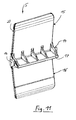
- FIG. 1 is a perspective view of a folding bunk (7) for a cab shown a truck.
- the foldable bunk (7) is in this embodiment on its one longitudinal side about bearings and on its other longitudinal side by means of two Straps (3) held in a position of use in the cab.
- a fixing rod (2) is attached to the straps (3) of a Sleeper (7) by means of the holding elements (1).
- the holding elements (1) are alternative uses for the latter conceivable, for example for the securing and fixing of components to be arranged in motor vehicles, Objects or luggage.
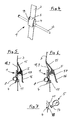
- the holding element (1) shown in Fig. 1 is in a closed position in perspective shown.
- the holding element (1) consists essentially of a housing (4) and a here rotatably mounted rocker (5).
- the belt (3) is between rocker (5) and housing (4) passed.
- the fixing rod (2) is passed and recorded.
- FIG. 3 is a side view and a sectional view of the retaining element (1) shown in FIG. 2. shown in a closed position.
- the first on the belt (3) longitudinally displaceable arranged holding element (1) is dependent on the Kippwinkel ein its associated Rocker (5) relative to the housing (4) in a closed position of the rocker (5) in a Load-resistant position fixing in any position on the belt (3) can be brought.
- the rocker (5) has two angularly arranged in this embodiment first and second rocker arms (15, 16) having a common pressure actuating surface exhibit.
- the closing position of the rocker (5) is by their positioning in one of the longitudinal course of the belt (3) achieved approximately parallel position (neutral Kippwinkel ein). There is one the rocker (5) associated locking web (17) with a holding element (1) associated Floor (9) with run-up gate (18) for clamping the between locking web (17) and bottom (9) passed through belt (3). In addition comes in this closing position of the Rocker (5) of the second rocker arm (16) on a crosspiece formed on the housing (4) (11) for investment.
- a receptacle (8) for attachment the fixing rod (2) provided.
- the receptacle (8) is designed here as a receiving eye and disposed in a lower portion of the housing (4).
- FIG. 4 is a perspective view of the holding element (1) in an inhibiting position of Rocker (5) shown.
- Fig. 5 is in side view and in sectional view located in this inhibit position Holding element (1) shown.
- this inhibition position of the rocker (5) is in a first Longitudinal direction of the belt (3) a self-locking, at least difficult to move position fixation of the holding element (1) in any position on the belt (3) allows.
- a second longitudinal direction of the belt (3) is a free displacement of the holding element (1) achievable on the belt (3).
- the inhibition position of the rocker (5) is by their positioning in a longitudinal course of the belt (3) slightly inclined position (first tilt angle position) can be achieved. It is the first rocker arm (15) and the locking web (1) of the rocker (5) approximately in a sliding contact brought with the belt (3), whereby a sliding in the one longitudinal direction and a Self-locking in the other longitudinal direction of the belt (3) is possible.
- Fig. 6 is in side view and in sectional view located in a shift position Holding element (1) shown.
- a shift position of the rocker (5) is a position beliebiebige free displacement of the retaining element (1) on the belt (3) in the two Longitudinal causes.
- the displacement position of the rocker (5) is by their positioning in a longitudinal course of the belt (3) more inclined position (second tilt angle position) achievable. It is the first rocker arm (15) into a manually executed force contact with the belt (3) and the locking web (1) of the rocker (5) optionally from the contact with the contact Belt (3) can be brought, whereby a free displacement of the retaining element on the belt (3) allows is.
- the positioning and the locking and unlocking of the retaining element (1) on the belt (3) is advantageously feasible with an operator's hand.
- Fig. 7 is a fragmentary and side view of an enlarged detail of the in a shift position located holding element (1) shown.
- the Arretiersteges (17) of the rocker (5) during a rotational movement of the rocker (5) on a movement path (21) guided in such a way that the end of the Arretiersteges (17) one in the bottom (9) of the housing (4) formed Auflaufkulisse (18) Continuously until complete clamping action from the locking bar (17), belt (3) and runway (18) approach and opposite Direction of rotation of the rocker (5) can remove it.
- the one not shown here, however between the locking web (17) and run-up scenery (18) located belt (3) can thus clamped, touched or released.
- Fig. 8 is a perspective and enlarged view in an inhibiting position located holding element (1) shown.
- the mutually parallel shoulders (10) of the housing (4) have approximately in their length half coaxial through holes (13) for articulated Recording of the end face of the rocker (5) formed pin (14) - as shown in Fig. 11 are - up.
- the end face of the rocker (5) formed pin (14) are here, for example, in about the length of half of the rocker (14) arranged on this.
- Fig. 9 is a perspective and enlarged view of the in a closed position located holding element (1) shown.
- the rocker (5) and the housing (4) have in this Embodiment approximately equal lengths.
- Both rocker arms (15, 16) have a the belt (3) facing, sliding skid-like Autex.
- the housing (4) of the holding element (1) is approximately a U-profile with the bottom (9) and the front side hereby formed and mutually parallel shoulders (10), in spaced from the Floor (9) of the transverse web (11) are bridged.
- This crosspiece (11) limits one end of the housing (4) has a passage (12) for the guided through this belt (3).
- FIG. 10 is a perspective and enlarged view of the housing (4) of the holding element (1) shown.
- the bottom (9) of the housing (4) is for the purpose of positioning the rocker (5) in the sliding position relative to the shoulders (10) of the housing (4) shortened executed.
- a more inclined position of the rocker (5) (second tilt angle position) be made possible with respect to the housing (4).
- the first rocker leg (15) can thus dipping between the two shoulders (10) of the housing (4).
- FIG. 11 is a perspective and enlarged view of the rocker (5) of the holding element (1) shown in a rear view.
- On a back of the rocker (5) is the about at right angles from this projecting, approximately at the level of the pin (14) extending locking web (17) arranged with a in the bottom (9) of the housing (14) formed Auflaufkulisse (18) (FIGS. 7 and 10) and between the run-up gate (18) and locking web (17) passed through Belt (3) corresponds such that on the different Kippwinkel einen the rocker (5) across their closing position, inhibition position and shift position achieved is.
Landscapes
- Engineering & Computer Science (AREA)
- Chemical & Material Sciences (AREA)
- Combustion & Propulsion (AREA)
- Transportation (AREA)
- Mechanical Engineering (AREA)
- Fittings On The Vehicle Exterior For Carrying Loads, And Devices For Holding Or Mounting Articles (AREA)
- Portable Nailing Machines And Staplers (AREA)
Applications Claiming Priority (2)
| Application Number | Priority Date | Filing Date | Title |
|---|---|---|---|
| DE10346876 | 2003-10-09 | ||
| DE2003146876 DE10346876A1 (de) | 2003-10-09 | 2003-10-09 | Halteelement für einen Kraffahrzeuggurt |
Publications (2)
| Publication Number | Publication Date |
|---|---|
| EP1522487A1 true EP1522487A1 (fr) | 2005-04-13 |
| EP1522487B1 EP1522487B1 (fr) | 2006-06-14 |
Family
ID=34306337
Family Applications (1)
| Application Number | Title | Priority Date | Filing Date |
|---|---|---|---|
| EP20040023013 Expired - Lifetime EP1522487B1 (fr) | 2003-10-09 | 2004-09-28 | Blocage de sangle pour véhicules |
Country Status (2)
| Country | Link |
|---|---|
| EP (1) | EP1522487B1 (fr) |
| DE (2) | DE10346876A1 (fr) |
Cited By (3)
| Publication number | Priority date | Publication date | Assignee | Title |
|---|---|---|---|---|
| WO2007069947A1 (fr) * | 2005-12-13 | 2007-06-21 | Volvo Lastvagnar Ab | Arrangement de couchette avec dispositif de separation |
| EP2022669A3 (fr) * | 2007-08-08 | 2009-03-25 | MAN Nutzfahrzeuge Aktiengesellschaft | Dispositif d'arrêt, en particulier pour un couchage d'une cabine de conducteur d'un véhicule utilitaire |
| CN112078457A (zh) * | 2020-08-07 | 2020-12-15 | 北汽福田汽车股份有限公司 | 车载卧铺总成及车辆 |
Citations (4)
| Publication number | Priority date | Publication date | Assignee | Title |
|---|---|---|---|---|
| US3364529A (en) * | 1965-12-20 | 1968-01-23 | Philip E. Blacher | Rope lock clamp |
| FR2631093A1 (fr) * | 1988-05-09 | 1989-11-10 | Letournel Gilles | Dispositif permettant l'accrochage et le reglage en hauteur d'un objet suspendu a un cordage sur un cable horizontal |
| EP1069031A2 (fr) | 1999-07-15 | 2001-01-17 | Klippan Safety Ab | Agencement de couchette dans une cabine de camion |
| US6292984B1 (en) * | 1999-09-27 | 2001-09-25 | Bradley E. Nelson | Load-support system employing instantaneously adjustable hook |
-
2003
- 2003-10-09 DE DE2003146876 patent/DE10346876A1/de not_active Withdrawn
-
2004
- 2004-09-28 EP EP20040023013 patent/EP1522487B1/fr not_active Expired - Lifetime
- 2004-09-28 DE DE200450000758 patent/DE502004000758D1/de not_active Expired - Lifetime
Patent Citations (4)
| Publication number | Priority date | Publication date | Assignee | Title |
|---|---|---|---|---|
| US3364529A (en) * | 1965-12-20 | 1968-01-23 | Philip E. Blacher | Rope lock clamp |
| FR2631093A1 (fr) * | 1988-05-09 | 1989-11-10 | Letournel Gilles | Dispositif permettant l'accrochage et le reglage en hauteur d'un objet suspendu a un cordage sur un cable horizontal |
| EP1069031A2 (fr) | 1999-07-15 | 2001-01-17 | Klippan Safety Ab | Agencement de couchette dans une cabine de camion |
| US6292984B1 (en) * | 1999-09-27 | 2001-09-25 | Bradley E. Nelson | Load-support system employing instantaneously adjustable hook |
Cited By (4)
| Publication number | Priority date | Publication date | Assignee | Title |
|---|---|---|---|---|
| WO2007069947A1 (fr) * | 2005-12-13 | 2007-06-21 | Volvo Lastvagnar Ab | Arrangement de couchette avec dispositif de separation |
| US7823962B2 (en) | 2005-12-13 | 2010-11-02 | Volvo Lastvagnar Ab | Bunk arrangement with partition device |
| EP2022669A3 (fr) * | 2007-08-08 | 2009-03-25 | MAN Nutzfahrzeuge Aktiengesellschaft | Dispositif d'arrêt, en particulier pour un couchage d'une cabine de conducteur d'un véhicule utilitaire |
| CN112078457A (zh) * | 2020-08-07 | 2020-12-15 | 北汽福田汽车股份有限公司 | 车载卧铺总成及车辆 |
Also Published As
| Publication number | Publication date |
|---|---|
| EP1522487B1 (fr) | 2006-06-14 |
| DE502004000758D1 (de) | 2006-07-27 |
| DE10346876A1 (de) | 2005-05-04 |
Similar Documents
| Publication | Publication Date | Title |
|---|---|---|
| DE3420574C2 (fr) | ||
| DE60021452T2 (de) | Blockiervorrichtung | |
| DE3890701C2 (de) | System für einen auf einem Fahrzeug montierten Lastenträger für ein Fahrrad oder eine andere Last | |
| DE19513520C1 (de) | Kraftfahrzeug mit einer Heckklappe, insbesondere für Mehrzweck- oder Kombiwagen | |
| DE19654395C1 (de) | Nocken zur lösbaren Verriegelung eines Bauteils, insbesondere an einem Kraftfahrzeugsitz | |
| DE60200799T2 (de) | Rettungsfahrzeug | |
| DE3911165C2 (de) | Sitzverschiebe-Vorrichtung | |
| DE102020105202A1 (de) | Vorrichtung zur translatorischen und rotatorischen Bewegung eines Gegenstands relativ zu einer Trägerplatte | |
| EP1107878B1 (fr) | Dispositif de fixation pour siege enfant | |
| EP0831001B1 (fr) | Rancher pour une bache | |
| DE19920386C2 (de) | Lager für eine umklappbare Rückenlehne | |
| DE2365921A1 (de) | Vorrichtung zum festlegen von unter einem flugzeug mitzufuehrenden lasten | |
| EP1522487A1 (fr) | Blocage de sangle pour véhicules | |
| DE3426207A1 (de) | Vorrichtung zur Höhenverstellung eines oberen Haltepunktes eines Sicherheitsgurtsystems | |
| DE69200109T2 (de) | Einrichtung zum Verkeilen von Fahrzeugen, die auf Böden von Transportanhängern oder Eisenbahnwaggons vorgesehen sind. | |
| DE10338723B4 (de) | Vorrichtung zum Transport von Gegenständen an einem Fahrzeugheck | |
| DE1940861C3 (de) | Abschließbarer Schiträger für Kraftfahrzeuge | |
| EP2011688B1 (fr) | Adaptateur pour un système d'arrêt de véhicule automobile | |
| DE19915315C2 (de) | Neigungsverstellvorrichtung für eine Fondsitzlehne | |
| DE10201622B4 (de) | Vorrichtung zum Verankern einer Last an einem Fahrzeugboden | |
| DE69209512T2 (de) | Faltbarer gepäckwagen | |
| DE19643806C2 (de) | Kindersportwagen mit einem von seinem Fahrgestell lösbaren Sitz | |
| DE60102620T2 (de) | Verbindungsvorrichtung für Befestigungsstangen an einem Kraftfahrzeug | |
| EP1707075B1 (fr) | Table pliante et ferrure pour table pliante | |
| DE102006005728B4 (de) | Rückenlehne für einen Fahrzeugsitz |
Legal Events
| Date | Code | Title | Description |
|---|---|---|---|
| PUAI | Public reference made under article 153(3) epc to a published international application that has entered the european phase |
Free format text: ORIGINAL CODE: 0009012 |
|
| AK | Designated contracting states |
Kind code of ref document: A1 Designated state(s): AT BE BG CH CY CZ DE DK EE ES FI FR GB GR HU IE IT LI LU MC NL PL PT RO SE SI SK TR |
|
| AX | Request for extension of the european patent |
Extension state: AL HR LT LV MK |
|
| 17P | Request for examination filed |
Effective date: 20050427 |
|
| GRAP | Despatch of communication of intention to grant a patent |
Free format text: ORIGINAL CODE: EPIDOSNIGR1 |
|
| AKX | Designation fees paid |
Designated state(s): DE FR IT SE |
|
| GRAS | Grant fee paid |
Free format text: ORIGINAL CODE: EPIDOSNIGR3 |
|
| GRAA | (expected) grant |
Free format text: ORIGINAL CODE: 0009210 |
|
| AK | Designated contracting states |
Kind code of ref document: B1 Designated state(s): DE FR IT SE |
|
| REF | Corresponds to: |
Ref document number: 502004000758 Country of ref document: DE Date of ref document: 20060727 Kind code of ref document: P |
|
| REG | Reference to a national code |
Ref country code: SE Ref legal event code: TRGR |
|
| ET | Fr: translation filed | ||
| PLBE | No opposition filed within time limit |
Free format text: ORIGINAL CODE: 0009261 |
|
| STAA | Information on the status of an ep patent application or granted ep patent |
Free format text: STATUS: NO OPPOSITION FILED WITHIN TIME LIMIT |
|
| 26N | No opposition filed |
Effective date: 20070315 |
|
| REG | Reference to a national code |
Ref country code: FR Ref legal event code: CD |
|
| REG | Reference to a national code |
Ref country code: DE Ref legal event code: R081 Ref document number: 502004000758 Country of ref document: DE Owner name: MAN TRUCK & BUS AG, DE Free format text: FORMER OWNER: MAN NUTZFAHRZEUGE AG, 80995 MUENCHEN, DE Effective date: 20110518 |
|
| REG | Reference to a national code |
Ref country code: FR Ref legal event code: PLFP Year of fee payment: 13 |
|
| REG | Reference to a national code |
Ref country code: FR Ref legal event code: PLFP Year of fee payment: 14 |
|
| REG | Reference to a national code |
Ref country code: FR Ref legal event code: PLFP Year of fee payment: 15 |
|
| REG | Reference to a national code |
Ref country code: DE Ref legal event code: R081 Ref document number: 502004000758 Country of ref document: DE Owner name: MAN TRUCK & BUS SE, DE Free format text: FORMER OWNER: MAN TRUCK & BUS AG, 80995 MUENCHEN, DE |
|
| PGFP | Annual fee paid to national office [announced via postgrant information from national office to epo] |
Ref country code: IT Payment date: 20230920 Year of fee payment: 20 |
|
| PGFP | Annual fee paid to national office [announced via postgrant information from national office to epo] |
Ref country code: SE Payment date: 20230926 Year of fee payment: 20 Ref country code: FR Payment date: 20230926 Year of fee payment: 20 Ref country code: DE Payment date: 20230928 Year of fee payment: 20 |
|
| REG | Reference to a national code |
Ref country code: DE Ref legal event code: R071 Ref document number: 502004000758 Country of ref document: DE |
|
| REG | Reference to a national code |
Ref country code: SE Ref legal event code: EUG |