EP1522494B1 - Wickel- und Bremsvorrichtung für eine Folie - Google Patents
Wickel- und Bremsvorrichtung für eine Folie Download PDFInfo
- Publication number
- EP1522494B1 EP1522494B1 EP02022013A EP02022013A EP1522494B1 EP 1522494 B1 EP1522494 B1 EP 1522494B1 EP 02022013 A EP02022013 A EP 02022013A EP 02022013 A EP02022013 A EP 02022013A EP 1522494 B1 EP1522494 B1 EP 1522494B1
- Authority
- EP
- European Patent Office
- Prior art keywords
- clamping
- braking
- film
- pressure roller
- lever
- Prior art date
- Legal status (The legal status is an assumption and is not a legal conclusion. Google has not performed a legal analysis and makes no representation as to the accuracy of the status listed.)
- Expired - Lifetime
Links
- 238000004804 winding Methods 0.000 claims abstract description 23
- 239000011888 foil Substances 0.000 abstract description 10
- 230000005540 biological transmission Effects 0.000 description 6
- 238000006073 displacement reaction Methods 0.000 description 3
- 238000010073 coating (rubber) Methods 0.000 description 2
- 239000011248 coating agent Substances 0.000 description 2
- 238000000576 coating method Methods 0.000 description 2
- 230000006835 compression Effects 0.000 description 2
- 238000007906 compression Methods 0.000 description 2
- 238000010276 construction Methods 0.000 description 2
- 239000000463 material Substances 0.000 description 1
- 238000004806 packaging method and process Methods 0.000 description 1
- 239000002985 plastic film Substances 0.000 description 1
- 229920006255 plastic film Polymers 0.000 description 1
- 230000036316 preload Effects 0.000 description 1
Images

Classifications
-
- B—PERFORMING OPERATIONS; TRANSPORTING
- B65—CONVEYING; PACKING; STORING; HANDLING THIN OR FILAMENTARY MATERIAL
- B65B—MACHINES, APPARATUS OR DEVICES FOR, OR METHODS OF, PACKAGING ARTICLES OR MATERIALS; UNPACKING
- B65B11/00—Wrapping, e.g. partially or wholly enclosing, articles or quantities of material, in strips, sheets or blanks, of flexible material
- B65B11/04—Wrapping, e.g. partially or wholly enclosing, articles or quantities of material, in strips, sheets or blanks, of flexible material the articles being rotated
- B65B11/045—Wrapping, e.g. partially or wholly enclosing, articles or quantities of material, in strips, sheets or blanks, of flexible material the articles being rotated by rotating platforms supporting the articles
Definitions
- the invention relates to a winding device for winding objects arranged in particular on a pallet with foil. Furthermore, the invention relates to a braking device for such winding devices.
- the objects are fixed on the pallet, for example for transport.
- the film which can also be pre-stretched to increase the packaging security, has essentially the task that the objects are held securely on the pallet.
- the film which is usually wound as 40 to 60 cm wide film tape on a roll, is often wrapped by hand around the pallet.
- winding devices such as pallet wrapping machines, by which an automatic wrapping of the pallet can be performed with foil.
- Such winding devices have a roll holder for receiving the film roll.
- the roll holder is, for example, a rotatable shaft on which the film roll is attached.
- the film is unwound from the film roll.
- the film is usually passed between a guide device and a pressure roller.
- the guide device may also be a roller.
- the pressure roller is connected to a braking device. This makes it possible, preferably with soft rubber Brake coated coating roller.
- the tension or bias is realized in the film by the braked rotation or the rotational speed of the pressure roller. The stronger the pressure roller is braked, the greater the preload in the film.
- electromagnetic brakes can be provided.
- electromagnetic brakes are structurally complex and therefore expensive.
- WO 90/06261 is a corresponding to the preambles of claims 1 and 2 winding device with a braking device known.
- the braking device described has a friction brake.
- the object of the invention is to provide a winding device for wrapping especially arranged on a pallet objects with foil and a braking device for to provide such winding devices, in which the braking of a pressure roller is carried out by a structurally simple and inexpensive construction, the braking should be possible in particular by means of a reproducible adjustable braking force.
- the object is achieved by a winding device according to claim 1 and a braking device according to claim 2.
- the winding device has a roll holder for receiving a film roll and a guide device for guiding the unwound from the film roll film.
- a guide device which may be a roller, presses a pressure roller.
- the pressure roller preferably has a coating which prevents the film from slipping, in particular a soft rubber coating.
- the pressure roller is connected to a first brake element, it being possible to press against the first brake element a second brake element for tensioning the film.
- the brake element is, for example, a brake disk and brake shoes pressing against the brake disk.
- a tensioning device is provided, which is preferably connected to the first brake element, wherein the two brake elements are compressible by the tensioning device.
- the clamping device according to the invention on a clamping lever, wherein by operating the clamping lever, ie, for example, by rotating or turning the clamping lever in a braking position, a defined braking force is generated.
- the invention relates to a braking device for a winding device for wrapping in particular arranged on a pallet objects with foil.
- the brake device has a pressure roller for tensioning the film, a first brake element connected to the pressure roller and a second brake element which can be pressed against the first brake element for tensioning the film.
- the braking device according to the invention also has a clamping device for compressing the brake elements, wherein the clamping device has a clamping lever, so that by pressing the clamping lever in a braking position, a defined braking force is generated.
- the brake device has the same advantages as the above-described winding device.
- the clamping lever is firmly connected to a clamping element.
- the clamping element according to the invention is designed such that by turning, ie pressing or moving the clamping lever together with the clamping element in the braking position, the brake elements are pressed against each other.
- the clamping element has at least two clamping surfaces. The clamping surfaces are arranged at a different distance from the axis of rotation of the clamping lever. By turning or pressing the clamping lever one of the clamping surfaces is thus rotated about the axis of rotation of the clamping lever and brought into the braking position. Due to the distance of the clamping surface to the axis of rotation of the clamping lever takes place automatically when rotating the clamping lever in the braking position, a compression of the two brake elements.
- the clamping surface which has a greater distance from the axis of rotation, a greater braking force is generated when the clamping lever is actuated such that this clamping surface is pivoted to the braking position.
- the clamping element it is possible to provide a plurality of clamping surfaces with different distances to the axis of rotation, so that the braking force in several stages adjustable is.
- the clamping element it is also possible to form the clamping element as an eccentric, so that the individual clamping surfaces merge into one another. There is thus a continuous increase in the distance between the clamping surface and the axis of rotation of the clamping lever when rotating the clamping lever. This results in a continuous increase in the braking force.
- the clamping surface preferably presses against a contact surface which is part of one of the two brake elements or is connected to one of the two brake elements.
- a spring element is provided between the tensioning device, in particular the tensioning element and the first or second braking element.
- the spring element which may be an elastic body or preferably a helical spring, is compressed by actuating the tensioning device, ie by flipping the tensioning lever. By the force of the spring element thus takes place the compression of the two brake elements.
- the tensioning device ie when rotating the tensioning lever from the braking position to an untensioned position
- a winding device for wrapping, for example, arranged on a pallet 10 objects 12, such as stacked boxes, has a receiving device 14. On the receiving device 14, the pallet is arranged. As a receiving device 14, for example, a turntable is provided which is rotatable about an axis 16. Furthermore, the winding device has a winding tower 18. The winding tower 18 carries a roll holder 20 which is vertically displaceable in the direction of the arrow 22. From the roll holder 20, the film roll 24 is supported. By turning the pallet 10 together with the cartons 12 about the axis 16, a film 26 is wrapped around the cartons. By simultaneously moving the roll holder 20 in the vertical direction, the wrapping of the cartons takes place over the entire height. Usually, a height sensor is provided, through which the height of the objects stacked on the pallet 10 is perceived. By the height sensor, the vertical displacement of the film roll 24 is limited.
- the roll holder 26 has a substantially L-shaped holding part 28 which carries a mandrel 30, on which the film roll 24 can be plugged.
- the film roll 24 is usually rotatably connected to the holder 28 together with the mandrel 30.
- the roll holder 28 is connected to a chain 32. By Drive the chain 32 is a vertical displacement of the roll holder 20 in the direction of arrow 22 (FIG. Fig. 1 ) possible.
- guide rails 34 are connected to the winding tower, where four rollers 36 abut.
- a guide device 38 is connected to the L-shaped holder 28 of the roll holder 20.
- the guide device 38 is a freely rotatably connected to the holder 28 and a holder 40 role.
- a pressure roller 42 is provided in the longitudinal direction of the roller 38. The two rollers 38,42 thus touch each other in the longitudinal direction along a line. Between the two rollers 38,42, the film 26 is passed.
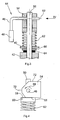
- the pressure roller 42 is connected to a brake device 44 according to the invention.
- the braking device 44 has a clamping lever 46 with handle 48.
- the tensioning lever 46 is rotatably mounted in a shaft 50 of the pressure roller 42.
- the axis of rotation 52 of the lever 46 extends perpendicular to the longitudinal direction of the pressure roller 42.
- a clamping element 54 is firmly connected.
- the clamping element 54 presses with a first clamping surface 56 in the in the FIGS. 3 and 4 From the transmission part 60 force is transmitted to a spring 62, which surrounds the shaft 50 and is arranged between the transmission part 60 and the holder 40 fixedly connected to the holder 40 , By the force transmission of the spring 62, the shaft 50 and thus the fixedly connected to the shaft 50 pressure roller 42 in Fig. 3 pulled up.
- a first brake element 64 fixedly connected to the pressure roller 42 is pressed against a second brake element 66 which is connected to the holder 40.
- the two brake elements 64,66 which may be, for example, a brake disc and a brake shoe, there is a braking of the pressure roller 42. Since the pressure roller 42 is preferably made of soft rubber or another material is avoided by the slippage of the film 26, 42 due to the braking action of the pressure roller, the voltage caused in the film 26 can be adjusted.
- the brake device 44 is easy to operate.
- the clamping element 54 By turning the lever 46 in the direction of an arrow 68 ( Fig. 4 ), the clamping element 54, for example, in Fig. 4 turned 90 ° to the left.
- a surface 70 of the tensioning element 54 rests against the contact surface 58 of the transmission part 60.
- the spring 62 is preferably designed such that the two brake elements 64,66 at concern of the surface 70th be pressed apart on the transmission part 60, so that no or only a very small friction between the two brake elements 64,66 occurs.
- the film 26 can easily between the two rollers 38,42 ( Fig. 2 ) and, for example, on the pallet 10 (FIG. Fig. 1 ) are attached.
- At least one of the two brake elements 64,66 may be slidably mounted in the longitudinal direction of the shaft 50.
- the first brake element 64 may be connected via a thread and a suitable lock nut with the shaft 50.
Landscapes
- Engineering & Computer Science (AREA)
- Mechanical Engineering (AREA)
- Basic Packing Technique (AREA)
- Controlling Rewinding, Feeding, Winding, Or Abnormalities Of Webs (AREA)
- Braking Arrangements (AREA)
- Registering, Tensioning, Guiding Webs, And Rollers Therefor (AREA)
Description
- Die Erfindung betrifft eine Wickelvorrichtung zum Wickeln von insbesondere auf einer Palette angeordneten Gegenständen mit Folie. Ferner betrifft die Erfindung eine Bremsvorrichtung für derartige Wickelvorrichtungen.
- Durch Umwickeln von beispielsweise auf Palette gestapelten Gegenständen, wie Kartons, mit einer dünnen Kunststofffolie werden die Gegenstände auf der Palette beispielsweise für den Transport fixiert. Die Folie, die zum Erhöhen der Verpackungssicherheit auch vorgestreckt sein kann, hat im Wesentlichen die Aufgabe, dass die Gegenstände auf der Palette sicher gehalten werden. Die Folie, die üblicherweise als 40 bis 60 cm breites Folienband auf einer Rolle aufgewickelt ist, wird häufig per Hand um die Palette gewickelt.
- Ferner sind Wickelvorrichtungen, wie Paletten-Einwickelmaschinen, bekannt, durch die ein automatisches Umwickeln der Palette mit Folie durchgeführt werden kann. Derartige Wickelvorrichtungen weisen zur Aufnahme der Folienrolle eine Rollenhalterung auf. Bei der Rollenhalterung handelt es sich beispielsweise um eine drehbare Welle, auf die die Folienrolle aufgesteckt wird. Zum Umwickeln der Gegenstände wird die Folie von der Folienrolle abgewickelt. Um die Folie zu spannen oder ein Strecken der Folie während des Umwickelns der Gegenstände zu ermöglichen, ist die Folie üblicherweise zwischen einer Führungseinrichtung und einer Andrückrolle hindurchgeführt. Bei der Führungseinrichtung kann es sich ebenfalls um eine Rolle handeln. Die Andrückrolle ist mit einer Bremsvorrichtung verbunden. Hierdurch ist es möglich, die vorzugsweise mit Weichgummi beschichtete Andrückrolle abzubremsen. Da die Folie insbesondere auf Grund der Weichgummibeschichtung nicht oder nur geringfügig über die Andrückrolle rutschen kann, wird durch das gebremste Drehen bzw. die Drehgeschwindigkeit der Andrückrolle die Spannung bzw. Vorspannung in der Folie realisiert. Je stärker die Andrückrolle gebremst wird, desto größer ist die Vorspannung in der Folie.
- Zum Einstellen der Bremskraft können beispielsweise elektromagnetische Bremsen vorgesehen sein. Elektromagnetische Bremsen sind jedoch konstruktiv aufwändig und daher teuer.
- Aus
WO 90/06261 - Aufgabe der Erfindung ist es, eine Wickelvorrichtung zum Umwickeln von insbesondere auf einer Palette angeordneten Gegenständen mit Folie sowie eine Bremsvorrichtung für derartige Wickelvorrichtungen zu schaffen, bei welcher das Bremsen einer Andrückrolle durch einen konstruktiv einfachen und kostengünstigen Aufbau erfolgt, wobei das Bremsen insbesondere mittels einer reproduzierbar einstellbaren Bremskraft möglich sein soll.
- Die Lösung der Aufgabe erfolgt durch eine Wickelvorrichtung gemäß Anspruch 1 bzw. eine Bremsvorrichtung gemäß Anspruch 2.
- Die erfindungsgemäße Wickelvorrichtung weist eine Rollenhalterung zur Aufnahme einer Folienrollen und eine Führungseinrichtung zum Führen der von der Folienrolle abgewickelten Folie auf. Gegen die Führungseinrichtung, bei der es sich um eine Rolle handeln kann, drückt eine Andrückrolle. Hierdurch wird ein Spannen der Folie realisiert. Die Andrückrolle weist vorzugsweise eine ein Durchrutschen der Folie verhindernde Beschichtung, insbesondere eine Weichgummibeschichtung, auf. Erfindungsgemäß ist die Andrückrolle mit einem ersten Bremselement verbunden, wobei gegen das erste Bremselement ein zweites Bremselement zum Spannen der Folie andrückbar ist. Bei dem Bremselement handelt es sich beispielsweise um eine Bremsscheibe und gegen die Bremsscheibe drückende Bremsbacken. Ferner ist eine Spannvorrichtung vorgesehen, die vorzugsweise mit dem ersten Bremselement verbunden ist, wobei durch die Spannvorrichtung die beiden Bremselemente zusammendrückbar sind. Hierzu weist die Spannvorrichtung erfindungsgemäß einen Spannhebel auf, wobei durch Betätigen des Spannhebels, d.h. beispielsweise durch Drehen oder Umlegen des Spannhebels in eine Bremsstellung, eine definierte Bremskraft erzeugt wird. Somit ist lediglich das Umlegen bzw. Betätigen eines Spannhebels erforderlich, um die beiden Bremselemente zusammen zu drücken bzw. die Bremsbacke gegen die Bremsscheibe zu drücken. Es handelt sich hierbei um einen einfachen und somit kostengünstigen Aufbau. Insbesondere ist eine derartige Bremsvorrichtung mit einem Spannhebel sehr wartungsfreundlich.
- Ferner betrifft die Erfindung eine Bremsvorrichtung für eine Wickelvorrichtung zum Umwickeln von insbesondere auf einer Palette angeordneten Gegenständen mit Folie. Die Bremsvorrichtung weist eine Andrückrolle zum Spannen der Folie, ein mit der Andrückrolle verbundenes erstes Bremselement und ein zweites Bremselement, das zum Spannen der Folie gegen das erste Bremselement drückbar ist, auf. Entsprechend der Wickelvorrichtung weist die erfindungsgemäße Bremsvorrichtung ebenfalls eine Spannvorrichtung zum Zusammendrücken der Bremselemente auf, wobei die Spannvorrichtung einen Spannhebel aufweist, so dass durch Betätigen des Spannhebels in eine Bremsstellung eine definierte Bremskraft erzeugt wird. Die Bremsvorrichtung weist dieselben Vorteile wie die vorstehend beschriebene Wickelvorrichtung auf.
- Der Spannhebel ist mit einem Spannelement fest verbunden. Das Spannelement ist erfindungsgemäß derart ausgebildet, dass durch Drehen, d.h. Betätigen oder Umlegen des Spannhebels zusammen mit dem Spannelement in die Bremsstellung, die Bremselemente gegeneinandergedrückt werden. Das Spannelement weist mindestens zwei Spannflächen auf. Die Spannflächen sind in einem unterschiedlichen Abstand zur Drehachse des Spannhebels angeordnet. Durch Drehen bzw. Betätigen des Spannhebels wird eine der Spannflächen somit um die Drehachse des Spannhebels gedreht und in die Bremsstellung gebracht. Auf Grund des Abstandes der Spannfläche zur Drehachse des Spannhebels erfolgt beim Drehen des Spannhebels in die Bremsstellung automatisch ein Zusammendrücken der beiden Bremselemente. Auf Grund des unterschiedlichen Abstandes ist es möglich, unterschiedliche Andrückkräfte zwischen den beiden Bremselementen zu erzeugen. Durch die Spannfläche, die einen größeren Abstand zur Drehachse aufweist, wird eine größere Bremskraft erzeugt, wenn der Spannhebel derart betätigt wird, dass diese Spannfläche in die Bremsstellung geschwenkt wird. Insbesondere ist es möglich, mehrere Spannflächen mit unterschiedlichen Abständen zur Drehachse vorzusehen, so dass die Bremskraft in mehreren Stufen einstellbar ist. Es ist ferner möglich, das Spannelement als Exzenter auszubilden, so dass die einzelnen Spannflächen ineinander übergehen. Es erfolgt somit eine kontinuierliche Zunahme des Abstandes zwischen der Spannfläche und der Drehachse des Spannhebels beim Drehen der Spannhebels. Hierdurch erfolgt eine kontinuierliche Zunahme der Bremskraft. Die Spannfläche drückt vorzugsweise gegen eine Anlagefläche, die Teil eines der beiden Bremselemente ist oder mit einem der beiden Bremselemente verbunden ist.
- Die folgende Beschreibung der bevorzugten Weiterbildungen betrifft sowohl die Wickelvorrichtung als auch die Bremsvorrichtung.
- Bei einer besonders bevorzugten Ausführungsform ist zwischen der Spannvorrichtung, insbesondere dem Spannelement und dem ersten oder zweiten Bremselement, ein Federelement vorgesehen. Das Federelement, bei dem es sich um einen elastischen Körper oder vorzugsweise eine Spiralfeder handeln kann, wird durch Betätigen der Spannvorrichtung, d.h. durch Umlegen des Spannhebels, zusammengedrückt. Durch die Kraft des Federelements erfolgt somit das Zusammendrücken der beiden Bremselemente. Andererseits ist beim Lösen der Spannvorrichtung, d.h. beim Drehen des Spannhebels aus der Bremsstellung in eine ungespannte Stellung, durch das Federelement sichergestellt, dass die beiden Bremselement auseinandergedrückt werden. Hierdurch kann in der entspannten Stellung die Folie mit geringer Reibung zwischen der Führungseinrichtung und der Andrückrolle hindurchgezogen werden, um beispielsweise an den zu umwickelnden Gegenständen befestigt zu werden. Hiernach erfolgt sodann ein Umlegen des Spannhebels in die bzw. eine der Bremsstellungen, um die gewünschte Bremskraft und damit die gewünschte Spannung der Folie zu erzeugen.
- Nachfolgend wird die Erfindung anhand einer bevorzugten Ausführungsform unter Bezugnahme auf die anliegenden Zeichnungen näher erläutert. Es zeigen:
- Fig. 1
- eine schematische Seitenansicht einer Wickelvorrichtung,
- Fig. 2
- eine schematische perspektivische Detailansicht der Rollenhalterung mit Bremsvorrichtung,
- Fig. 3
- eine schematische Schnittansicht der Bremsvorrichtung und
- Fig. 4
- eine schematische Detailansicht des Spannelements.
- Eine Wickelvorrichtung zum Umwickeln von beispielsweise auf einer Palette 10 angeordneten Gegenständen 12, wie beispielsweise übereinandergestapelten Kartons, weist eine Aufnahmeeinrichtung 14 auf. Auf der Aufnahmeeinrichtung 14 ist die Palette angeordnet. Als Aufnahmeeinrichtung 14 ist beispielsweise ein Drehteller vorgesehen, der um eine Achse 16 drehbar ist. Ferner weist die Wickelvorrichtung einen Wickelturm 18 auf. Der Wickelturm 18 trägt eine Rollenhalterung 20, die vertikal in Richtung des Pfeils 22 verschiebbar ist. Von der Rollenhalterung 20 wird die Folienrolle 24 getragen. Durch Drehen der Palette 10 zusammen mit den Kartons 12 um die Achse 16 wird eine Folie 26 um die Kartons gewickelt. Durch gleichzeitiges Verschieben der Rollenhalterung 20 in vertikale Richtung erfolgt das Umwickeln der Kartons über die gesamte Hö-he. Üblicherweise ist ein Höhensensor vorgesehen, durch den die Höhe der auf der Palette 10 gestapelten Gegenstände wahrgenommen wird. Durch den Höhensensor wird das vertikale Verschieben der Folienrolle 24 beschränkt.
- Die Rollenhalterung 26 weist ein im wesentlichen L-förmiges Halteteil 28 auf, das einen Dorn 30 trägt, auf den die Folienrolle 24 aufsteckbar ist. Die Folienrolle 24 ist üblicherweise zusammen mit dem Dorn 30 drehbar mit der Halterung 28 verbunden. Die Rollenhalterung 28 ist mit einer Kette 32 verbunden. Durch Antrieb der Kette 32 ist ein vertikales Verschieben der Rollenhalterung 20 in Richtung des Pfeils 22 (
Fig. 1 ) möglich. Zur Führung der Rollenhalterung 20 sind mit dem Wickelturm 18 Führungsschienen 34 verbunden, an denen vier Rollen 36 anliegen. - Mit der L-förmigen Halterung 28 der Rollenhalterung 20 ist ferner eine Führungseinrichtung 38 verbunden. Im dargestellten Ausführungsbeispiel handelt es sich bei der Führungseinrichtung 38 um eine frei drehbar mit der Halterung 28 sowie einer Halterung 40 verbundenen Rolle. In Längsrichtung der Rolle 38 ist eine Andrückrolle 42 vorgesehen. Die beiden Rollen 38,42 berühren sich somit in Längsrichtung entlang einer Linie. Zwischen den beiden Rollen 38,42 ist die Folie 26 hindurchgeführt. Die Andrückrolle 42 ist mit einer erfindungsgemäßen Bremsvorrichtung 44 verbunden.
- Die Bremsvorrichtung 44 weist einen Spannhebel 46 mit Griff 48 auf. Der Spannhebel 46 ist in einer Welle 50 der Andrückrolle 42 drehbar gelagert. Hierbei verläuft die Drehachse 52 des Hebels 46 senkrecht zur Längsrichtung der Andrückrolle 42. Mit dem Hebel 46 ist ein Spannelement 54 fest verbunden. Das Spannelement 54 drückt mit einer ersten Spannfläche 56 in der in den
Fign. 3 und 4 dargestellten Bremsstellung gegen eine Anlagefläche 58 eines ringförmigen, die Welle 50 umgebenden Übertragungsteils 60. Von dem Übertragungsteil 60 wird Kraft auf eine Feder 62 übertragen, die die Welle 50 umgibt und zwischen dem Übertragungsteil 60 und der fest mit der Halterung 28 verbundenen Halterung 40 angeordnet ist. Durch die Kraftübertragung der Feder 62 wird die Welle 50 und damit die fest mit der Welle 50 verbundene Andrückrolle 42 inFig. 3 nach oben gezogen. Hierdurch wird ein erstes mit der Andrückrolle 42 fest verbundenes Bremselement 64 gegen ein zweites Bremselement 66, das mit der Halterung 40 verbunden ist, gedrückt. Zwischen den beiden Bremselementen 64,66, bei denen es sich beispielsweise um eine Bremsscheibe und eine Bremsbacke handeln kann, erfolgt ein Bremsen der Andrückrolle 42. Da die Andrückrolle 42 vorzugsweise aus Weichgummi oder einem anderen Material besteht, durch das ein Rutschen der Folie 26 vermieden ist, kann auf Grund der Bremswirkung der Andrückrolle 42 die in der Folie 26 hervorgerufene Spannung eingestellt werden. - Erfindungsgemäß ist die Bremsvorrichtung 44 einfach zu betätigen. Durch Umlegen des Hebels 46 in Richtung eines Pfeils 68 (
Fig. 4 ) wird das Spannelement 54 beispielsweise inFig. 4 um 90° nach links gedreht. Hierdurch liegt an der Anlagefläche 58 des Übertragungsteils 60 eine Fläche 70 des Spannelements 54 an. Da die Fläche 70 zur Drehachse 52 des Spannhebels 46 einen geringen Abstand aufweist als die Spannfläche 56 zur Drehachse 52, erfolgt ein Entspannen der Feder 62. Hierbei ist die Feder 62 vorzugsweise derart ausgelegt, dass die beiden Bremselemente 64,66 bei Anliegen der Fläche 70 an dem Übertragungsteil 60 auseinandergedrückt werden, so dass keine oder nur noch eine sehr geringe Reibung zwischen den beiden Bremselementen 64,66 auftritt. In dieser Stellung kann die Folie 26 leicht zwischen den beiden Rollen 38,42 (Fig. 2 ) hindurchgezogen und beispielsweise an der Palette 10 (Fig. 1 ) befestigt werden. - Zur Erhöhung der Bremskraft kann der Hebel 46 aus der in den
Fign. 3 und 4 dargestellten Stellung in Richtung des Pfeils 68 auch um 180° gedreht werden, so dass eine zweite Spannfläche 73 an der Anlagefläche 58 des Übertragungsteils 60 anliegt. Da der Abstand der zweiten Spannfläche 62 zur Drehachse 52 des Spannhebels 46 größer ist als der Abstand der ersten Spannfläche 56 zu der Drehachse 52, ist die auf die Feder 62 übertragene Kraft größer. Hierdurch wird die Reibung zwischen den beiden Bremselementen 64,66 erhöht. - Durch Betätigen des Spannhebels 46 erfolgt somit ein Verschieben der Abdrückrolle 42 in ihrer Längsrichtung, wobei hierdurch die Bremskraft zwischen den beiden Bremselementen 64,66 eingestellt wird.
- Zur Feineinstellung der Bremskraft zwischen den beiden Bremselementen 64,66 kann zumindest eines der beiden Bremselementen 64,66 in Längsrichtung der Welle 50 verschiebbar befestigt sein. Hierzu kann beispielsweise das erste Bremselement 64 über ein Gewinde und eine geeignete Kontermutter mit der Welle 50 verbunden sein.
Claims (5)
- Wickelvorrichtung zum Umwickeln von insbesondere auf einer Palette (10) angeordneten Gegenständen (12) mit Folie (26), mit
einer Rollenhalterung (20) zur Aufnahme einer Folienrolle (24),
einer Führungseinrichtung (38) zum Führen der von der Folienrolle (24) abgewickelten Folie (26),
einer gegen die Führungseinrichtung (38) drückenden Andrückrolle (42) zum Spannen der Folie (26),
einem mit der Andrückrolle (42) verbundenen ersten Bremselement (64), gegen das ein zweites Bremselement (66) zum Spannen der Folie (26) andrückbar ist, und
einer Spannvorrichtung (46,54,62) zum Zusammendrücken der Bremselemente (64,66), wobei die Spannvorrichtung (46,54,62) einen Spannhebel (46) aufweist,
dadurch gekennzeichnet, dass
der Spannhebel (46) mit einem Spannelement (54) fest verbunden ist, das mindestens zwei unterschiedlichen Bremsstellungen entsprechenden Spannflächen (56, 72) mit unterschiedlichem Abstand zur Drehachse (52) des Spannhebels (46) zum Erzeugen unterschiedlicher Bremskräfte aufweist, und derart ausgebildet ist, dass durch Drehen des Spannhebels (46) zusammen mit dem Spannelement (54) in eine Bremsstellung die Bremselemente (64,66) gegeneinandergedrückt werden, so dass durch Betätigen des Spannhebels (46) in eine Bremsstellung eine definierte Bremskraft zwischen den Bremselementen (64,66) erzeugt wird. - Bremsvorrichtung für eine Wickelvorrichtung zum Umwickeln von insbesondere auf einer Palette (10) angeordneten Gegenständen (12) mit einer Folie (26), mit
einer Andrückrolle (42) zum Spannen der Folie,
einem mit der Andrückrolle (42) verbundenen ersten Bremselement (64), gegen das ein zweites Bremselement (66) zum Spannen der Folie (26) andrückbar ist, und
einer Spannvorrichtung (46,54,62) zum Zusammendrücken der Bremselemente (64,66),
wobei die Spannvorrichtung (46,54,62) einen Spannhebel (46) aufweist,
dadurch gekennzeichnet, dass
der Spannhebel (46) mit einem Spannelement (54) fest verbunden ist, dass mindestens zwei unterschiedlichen Bremsstellungen entsprechenden Spannflächen (56, 72) mit unterschiedlichem Abstand zur Drehachse (52) des Spannhebels (46) aufweist, und derart ausgebildet ist, dass durch Drehen des Spannhebels (46) zum Erzeugen unterschiedlicher Bremskräfte zusammen mit dem Spannelement (54) in die Bremsstellung die Bremselemente (64,66) gegeneinandergedrückt werden, so dass durch Betätigen des Spannhebels (46) in eine Bremsstellung eine definierte Bremskraft zwischen den Bremselementen (64,66) erzeugt wird. - Vorrichtung nach Anspruch 1 oder 2, dadurch gekennzeichnet, dass zwischen der Spannvorrichtung (46,54,62), insbesondere dem Spannhebel (46) und dem ersten oder zweiten Bremselement (64,66), ein Federelement (62) vorgesehen ist, das durch die Spannvorrichtung (46,54,62) zusammendrückbar ist.
- Vorrichtung nach einem der Ansprüche 1-3, dadurch gekennzeichnet, dass der Spannhebel (46) mit einer Welle (50) der Andrückrolle (42) verbunden ist.
- Vorrichtung nach Anspruch 4, dadurch gekennzeichnet, dass durch Betätigen des Spannhebels (46) die Andrückrolle (42) in Längsrichtung verschiebbar ist.
Priority Applications (4)
| Application Number | Priority Date | Filing Date | Title |
|---|---|---|---|
| AT02022013T ATE388085T1 (de) | 2002-10-01 | 2002-10-01 | Wickel- und bremsvorrichtung für eine folie |
| ES02022013T ES2301598T3 (es) | 2002-10-01 | 2002-10-01 | Dispositivo para el enrollado y frenado de una pelicula plastica. |
| DE50211865T DE50211865D1 (de) | 2002-10-01 | 2002-10-01 | Wickel- und Bremsvorrichtung für eine Folie |
| EP02022013A EP1522494B1 (de) | 2002-10-01 | 2002-10-01 | Wickel- und Bremsvorrichtung für eine Folie |
Applications Claiming Priority (1)
| Application Number | Priority Date | Filing Date | Title |
|---|---|---|---|
| EP02022013A EP1522494B1 (de) | 2002-10-01 | 2002-10-01 | Wickel- und Bremsvorrichtung für eine Folie |
Publications (2)
| Publication Number | Publication Date |
|---|---|
| EP1522494A1 EP1522494A1 (de) | 2005-04-13 |
| EP1522494B1 true EP1522494B1 (de) | 2008-03-05 |
Family
ID=34306745
Family Applications (1)
| Application Number | Title | Priority Date | Filing Date |
|---|---|---|---|
| EP02022013A Expired - Lifetime EP1522494B1 (de) | 2002-10-01 | 2002-10-01 | Wickel- und Bremsvorrichtung für eine Folie |
Country Status (4)
| Country | Link |
|---|---|
| EP (1) | EP1522494B1 (de) |
| AT (1) | ATE388085T1 (de) |
| DE (1) | DE50211865D1 (de) |
| ES (1) | ES2301598T3 (de) |
Families Citing this family (4)
| Publication number | Priority date | Publication date | Assignee | Title |
|---|---|---|---|---|
| ES2341209B1 (es) | 2008-07-22 | 2011-05-11 | Aranguren Comercial Del Embalaje, S.L. | Maquina enfardadora. |
| IT1393060B1 (it) * | 2008-10-22 | 2012-04-11 | Siro S R L | Dispositivo di supporto e frenatura regolabile della bobina di alimentazione di film di materiale plastico in macchine di imballaggio. |
| US11827473B2 (en) * | 2021-04-12 | 2023-11-28 | TG Plastic Technologies SDN, BHD. | Dispenser of stretch wrap |
| CN114229083B (zh) * | 2021-12-06 | 2023-06-06 | 日照圣谷山茶场有限公司 | 一种自动化茶砖绕线包装装置 |
Family Cites Families (2)
| Publication number | Priority date | Publication date | Assignee | Title |
|---|---|---|---|---|
| FR2608140B3 (fr) * | 1986-12-09 | 1988-12-30 | Deome Plastiques | Support de devidage manuel freine pour bobine de film etirable |
| FI81539C (fi) * | 1988-11-25 | 1990-11-12 | Newtec Int | Filmdelningskaelke foer en vecklingsmaskin. |
-
2002
- 2002-10-01 EP EP02022013A patent/EP1522494B1/de not_active Expired - Lifetime
- 2002-10-01 AT AT02022013T patent/ATE388085T1/de not_active IP Right Cessation
- 2002-10-01 DE DE50211865T patent/DE50211865D1/de not_active Expired - Lifetime
- 2002-10-01 ES ES02022013T patent/ES2301598T3/es not_active Expired - Lifetime
Also Published As
| Publication number | Publication date |
|---|---|
| DE50211865D1 (de) | 2008-04-17 |
| ES2301598T3 (es) | 2008-07-01 |
| EP1522494A1 (de) | 2005-04-13 |
| ATE388085T1 (de) | 2008-03-15 |
Similar Documents
| Publication | Publication Date | Title |
|---|---|---|
| DE69405151T2 (de) | Gerät zum Schneiden einer Materialbahn auf bestimmte Länge und zum Ausgeben derselben | |
| DE3048315A1 (de) | Vorrichtung zum abgeben von folie, insbesondere kunststoff-spann-folie fuer verpackungszwecke | |
| DE1774704A1 (de) | Vorrichtung zum Wickeln von Metallbandspulen | |
| DE2151548C3 (de) | Kartentransportvorrichtung | |
| DE4013656C2 (de) | Vorrichtung zum Spleißen von Bahnen, insbesondere von Papierbahnen für die Herstellung von Wellpappe | |
| DE3935043A1 (de) | Plotter mit einer bremse fuer eine zufuehrwalze | |
| DE2816862A1 (de) | Rohrbiegemaschine und -verfahren | |
| DE4339766C1 (de) | Vorrichtung zum Verhindern von Schäden bei Rissen von Warenbahnen | |
| EP1522494B1 (de) | Wickel- und Bremsvorrichtung für eine Folie | |
| DE2825102C2 (de) | Vorschubvorrichtung für eine Etiketten- Trägerbahn | |
| EP3300586A1 (de) | Ballenpresse | |
| DE2908294C3 (de) | Vorrichtung zum Aufwickeln von bahnförmigem Gut, z.B. von Papier | |
| DE2713524C2 (de) | ||
| EP0439830A2 (de) | Vorrichtung zur Be- oder Verarbeitung einer Materialbahn | |
| DE3346997C2 (de) | Vorrichtung zum Aufreihen elektrischer Bauelemente zu einem Gurt | |
| EP4157729B1 (de) | Bandbreitenanpassbare banderoliermaschine | |
| DE10013290A1 (de) | Haltevorrichtung für Stretchfolienrollen | |
| DE3922664C2 (de) | ||
| DE69300282T2 (de) | Vorrichtung zum Verbinden von Bändern aus weichem Material. | |
| DE20115649U1 (de) | Wickel- und Bremsvorrichtung | |
| DE1574637C3 (de) | Einrichtung (Bandlaufwerk) zur Bewegung eines sich zwischen einer Abwickelspule und einer Aufwickelspule erstreckenden Bandes, insbesondere eines Magnetbandes | |
| DE2106683C3 (de) | Vorrichtung zum Spannen von in Streifen geschnittenen Bändern | |
| DE19652448C9 (de) | Vorrichtung zum Verpacken einer Materialbahnrolle mit einer Verpackungsbahn | |
| DE2323430A1 (de) | Wickelvorrichtung zum abwickeln einer materialbahn von einer vorratsrolle | |
| EP1280725B1 (de) | Vorrichtung und verfahren zum spannen einer zu fördernden, flächigen materialbahn mittels drehzahlunterschied |
Legal Events
| Date | Code | Title | Description |
|---|---|---|---|
| PUAI | Public reference made under article 153(3) epc to a published international application that has entered the european phase |
Free format text: ORIGINAL CODE: 0009012 |
|
| AK | Designated contracting states |
Kind code of ref document: A1 Designated state(s): AT BE BG CH CY CZ DE DK EE ES FI FR GB GR IE IT LI LU MC NL PT SE SK TR |
|
| AX | Request for extension of the european patent |
Extension state: AL LT LV MK RO SI |
|
| 17P | Request for examination filed |
Effective date: 20050402 |
|
| APAF | Appeal reference modified |
Free format text: ORIGINAL CODE: EPIDOSCREFNE |
|
| APAF | Appeal reference modified |
Free format text: ORIGINAL CODE: EPIDOSCREFNE |
|
| AKX | Designation fees paid |
Designated state(s): AT BE BG CH CY CZ DE DK EE ES FI FR GB GR IE IT LI LU MC NL PT SE SK TR |
|
| 17Q | First examination report despatched |
Effective date: 20070208 |
|
| GRAP | Despatch of communication of intention to grant a patent |
Free format text: ORIGINAL CODE: EPIDOSNIGR1 |
|
| GRAS | Grant fee paid |
Free format text: ORIGINAL CODE: EPIDOSNIGR3 |
|
| GRAA | (expected) grant |
Free format text: ORIGINAL CODE: 0009210 |
|
| AK | Designated contracting states |
Kind code of ref document: B1 Designated state(s): AT BE BG CH CY CZ DE DK EE ES FI FR GB GR IE IT LI LU MC NL PT SE SK TR |
|
| REG | Reference to a national code |
Ref country code: GB Ref legal event code: FG4D Free format text: NOT ENGLISH |
|
| REG | Reference to a national code |
Ref country code: CH Ref legal event code: EP |
|
| REG | Reference to a national code |
Ref country code: IE Ref legal event code: FG4D Free format text: LANGUAGE OF EP DOCUMENT: GERMAN |
|
| REF | Corresponds to: |
Ref document number: 50211865 Country of ref document: DE Date of ref document: 20080417 Kind code of ref document: P |
|
| REG | Reference to a national code |
Ref country code: ES Ref legal event code: FG2A Ref document number: 2301598 Country of ref document: ES Kind code of ref document: T3 |
|
| PG25 | Lapsed in a contracting state [announced via postgrant information from national office to epo] |
Ref country code: FI Free format text: LAPSE BECAUSE OF FAILURE TO SUBMIT A TRANSLATION OF THE DESCRIPTION OR TO PAY THE FEE WITHIN THE PRESCRIBED TIME-LIMIT Effective date: 20080305 |
|
| NLV1 | Nl: lapsed or annulled due to failure to fulfill the requirements of art. 29p and 29m of the patents act | ||
| ET | Fr: translation filed | ||
| REG | Reference to a national code |
Ref country code: IE Ref legal event code: FD4D |
|
| PG25 | Lapsed in a contracting state [announced via postgrant information from national office to epo] |
Ref country code: SK Free format text: LAPSE BECAUSE OF FAILURE TO SUBMIT A TRANSLATION OF THE DESCRIPTION OR TO PAY THE FEE WITHIN THE PRESCRIBED TIME-LIMIT Effective date: 20080305 Ref country code: SE Free format text: LAPSE BECAUSE OF FAILURE TO SUBMIT A TRANSLATION OF THE DESCRIPTION OR TO PAY THE FEE WITHIN THE PRESCRIBED TIME-LIMIT Effective date: 20080605 Ref country code: CZ Free format text: LAPSE BECAUSE OF FAILURE TO SUBMIT A TRANSLATION OF THE DESCRIPTION OR TO PAY THE FEE WITHIN THE PRESCRIBED TIME-LIMIT Effective date: 20080305 Ref country code: NL Free format text: LAPSE BECAUSE OF FAILURE TO SUBMIT A TRANSLATION OF THE DESCRIPTION OR TO PAY THE FEE WITHIN THE PRESCRIBED TIME-LIMIT Effective date: 20080305 Ref country code: PT Free format text: LAPSE BECAUSE OF FAILURE TO SUBMIT A TRANSLATION OF THE DESCRIPTION OR TO PAY THE FEE WITHIN THE PRESCRIBED TIME-LIMIT Effective date: 20080805 |
|
| PLBE | No opposition filed within time limit |
Free format text: ORIGINAL CODE: 0009261 |
|
| STAA | Information on the status of an ep patent application or granted ep patent |
Free format text: STATUS: NO OPPOSITION FILED WITHIN TIME LIMIT |
|
| PG25 | Lapsed in a contracting state [announced via postgrant information from national office to epo] |
Ref country code: DK Free format text: LAPSE BECAUSE OF FAILURE TO SUBMIT A TRANSLATION OF THE DESCRIPTION OR TO PAY THE FEE WITHIN THE PRESCRIBED TIME-LIMIT Effective date: 20080305 Ref country code: IE Free format text: LAPSE BECAUSE OF FAILURE TO SUBMIT A TRANSLATION OF THE DESCRIPTION OR TO PAY THE FEE WITHIN THE PRESCRIBED TIME-LIMIT Effective date: 20080305 |
|
| 26N | No opposition filed |
Effective date: 20081208 |
|
| PG25 | Lapsed in a contracting state [announced via postgrant information from national office to epo] |
Ref country code: EE Free format text: LAPSE BECAUSE OF FAILURE TO SUBMIT A TRANSLATION OF THE DESCRIPTION OR TO PAY THE FEE WITHIN THE PRESCRIBED TIME-LIMIT Effective date: 20080305 Ref country code: BG Free format text: LAPSE BECAUSE OF FAILURE TO SUBMIT A TRANSLATION OF THE DESCRIPTION OR TO PAY THE FEE WITHIN THE PRESCRIBED TIME-LIMIT Effective date: 20080605 |
|
| PG25 | Lapsed in a contracting state [announced via postgrant information from national office to epo] |
Ref country code: MC Free format text: LAPSE BECAUSE OF NON-PAYMENT OF DUE FEES Effective date: 20081031 |
|
| REG | Reference to a national code |
Ref country code: CH Ref legal event code: PL |
|
| PG25 | Lapsed in a contracting state [announced via postgrant information from national office to epo] |
Ref country code: CY Free format text: LAPSE BECAUSE OF FAILURE TO SUBMIT A TRANSLATION OF THE DESCRIPTION OR TO PAY THE FEE WITHIN THE PRESCRIBED TIME-LIMIT Effective date: 20080305 |
|
| PG25 | Lapsed in a contracting state [announced via postgrant information from national office to epo] |
Ref country code: LI Free format text: LAPSE BECAUSE OF NON-PAYMENT OF DUE FEES Effective date: 20081031 Ref country code: CH Free format text: LAPSE BECAUSE OF NON-PAYMENT OF DUE FEES Effective date: 20081031 |
|
| PG25 | Lapsed in a contracting state [announced via postgrant information from national office to epo] |
Ref country code: AT Free format text: LAPSE BECAUSE OF NON-PAYMENT OF DUE FEES Effective date: 20081001 |
|
| PG25 | Lapsed in a contracting state [announced via postgrant information from national office to epo] |
Ref country code: LU Free format text: LAPSE BECAUSE OF NON-PAYMENT OF DUE FEES Effective date: 20081001 |
|
| PG25 | Lapsed in a contracting state [announced via postgrant information from national office to epo] |
Ref country code: TR Free format text: LAPSE BECAUSE OF FAILURE TO SUBMIT A TRANSLATION OF THE DESCRIPTION OR TO PAY THE FEE WITHIN THE PRESCRIBED TIME-LIMIT Effective date: 20080305 |
|
| PG25 | Lapsed in a contracting state [announced via postgrant information from national office to epo] |
Ref country code: GR Free format text: LAPSE BECAUSE OF FAILURE TO SUBMIT A TRANSLATION OF THE DESCRIPTION OR TO PAY THE FEE WITHIN THE PRESCRIBED TIME-LIMIT Effective date: 20080606 |
|
| PGFP | Annual fee paid to national office [announced via postgrant information from national office to epo] |
Ref country code: FR Payment date: 20121107 Year of fee payment: 11 Ref country code: DE Payment date: 20121029 Year of fee payment: 11 Ref country code: BE Payment date: 20121025 Year of fee payment: 11 |
|
| PGFP | Annual fee paid to national office [announced via postgrant information from national office to epo] |
Ref country code: ES Payment date: 20121026 Year of fee payment: 11 Ref country code: GB Payment date: 20121025 Year of fee payment: 11 Ref country code: IT Payment date: 20121023 Year of fee payment: 11 |
|
| BERE | Be: lapsed |
Owner name: ILLINOIS TOOL WORKS INC. Effective date: 20131031 |
|
| GBPC | Gb: european patent ceased through non-payment of renewal fee |
Effective date: 20131001 |
|
| REG | Reference to a national code |
Ref country code: DE Ref legal event code: R119 Ref document number: 50211865 Country of ref document: DE Effective date: 20140501 |
|
| PG25 | Lapsed in a contracting state [announced via postgrant information from national office to epo] |
Ref country code: GB Free format text: LAPSE BECAUSE OF NON-PAYMENT OF DUE FEES Effective date: 20131001 |
|
| REG | Reference to a national code |
Ref country code: FR Ref legal event code: ST Effective date: 20140630 |
|
| PG25 | Lapsed in a contracting state [announced via postgrant information from national office to epo] |
Ref country code: IT Free format text: LAPSE BECAUSE OF NON-PAYMENT OF DUE FEES Effective date: 20131001 Ref country code: DE Free format text: LAPSE BECAUSE OF NON-PAYMENT OF DUE FEES Effective date: 20140501 Ref country code: FR Free format text: LAPSE BECAUSE OF NON-PAYMENT OF DUE FEES Effective date: 20131031 |
|
| PG25 | Lapsed in a contracting state [announced via postgrant information from national office to epo] |
Ref country code: BE Free format text: LAPSE BECAUSE OF NON-PAYMENT OF DUE FEES Effective date: 20131031 |
|
| REG | Reference to a national code |
Ref country code: ES Ref legal event code: FD2A Effective date: 20141107 |
|
| PG25 | Lapsed in a contracting state [announced via postgrant information from national office to epo] |
Ref country code: ES Free format text: LAPSE BECAUSE OF NON-PAYMENT OF DUE FEES Effective date: 20131002 |