EP1522511B1 - Dispositif de chargement et d'extraction de camions des tuiles vers les/des machines du chargement et déchargement - Google Patents
Dispositif de chargement et d'extraction de camions des tuiles vers les/des machines du chargement et déchargement Download PDFInfo
- Publication number
- EP1522511B1 EP1522511B1 EP04077632A EP04077632A EP1522511B1 EP 1522511 B1 EP1522511 B1 EP 1522511B1 EP 04077632 A EP04077632 A EP 04077632A EP 04077632 A EP04077632 A EP 04077632A EP 1522511 B1 EP1522511 B1 EP 1522511B1
- Authority
- EP
- European Patent Office
- Prior art keywords
- truck
- tile
- section
- loading
- tile truck
- Prior art date
- Legal status (The legal status is an assumption and is not a legal conclusion. Google has not performed a legal analysis and makes no representation as to the accuracy of the status listed.)
- Expired - Lifetime
Links
- 238000006073 displacement reaction Methods 0.000 claims description 3
- 230000003247 decreasing effect Effects 0.000 claims description 2
- 210000000056 organ Anatomy 0.000 description 5
- 239000000919 ceramic Substances 0.000 description 1
- 238000000151 deposition Methods 0.000 description 1
- 230000000694 effects Effects 0.000 description 1
- 230000037361 pathway Effects 0.000 description 1
- 238000007790 scraping Methods 0.000 description 1
Images

Classifications
-
- B—PERFORMING OPERATIONS; TRANSPORTING
- B65—CONVEYING; PACKING; STORING; HANDLING THIN OR FILAMENTARY MATERIAL
- B65G—TRANSPORT OR STORAGE DEVICES, e.g. CONVEYORS FOR LOADING OR TIPPING, SHOP CONVEYOR SYSTEMS OR PNEUMATIC TUBE CONVEYORS
- B65G47/00—Article or material-handling devices associated with conveyors; Methods employing such devices
- B65G47/22—Devices influencing the relative position or the attitude of articles during transit by conveyors
-
- B—PERFORMING OPERATIONS; TRANSPORTING
- B65—CONVEYING; PACKING; STORING; HANDLING THIN OR FILAMENTARY MATERIAL
- B65G—TRANSPORT OR STORAGE DEVICES, e.g. CONVEYORS FOR LOADING OR TIPPING, SHOP CONVEYOR SYSTEMS OR PNEUMATIC TUBE CONVEYORS
- B65G65/00—Loading or unloading
Definitions
- the invention relates to an apparatus used for loading and unloading single trucks located at a predetermined position with respect to a loading-unloading machine, according to the preamble of claim 1.
- a truck In the ceramic industry a truck is basically a shelf rack, provided with a plurality of parallel planes on rollers on which tiles are piled at the end of various work stages; the truck is transferred from one machine or work station to another, and is in effect a vector for the tiles.
- Each work machine or station in a work cycle is equipped with a loading/unloading machine which transfers the tiles from the trucks to the work station, and vice versa.
- the apparatus of the invention can be used to feed in and extract the trucks from the loading and unloading machines.
- Spherical roller conveyors for handling heavy palletized loads are disclosed in US-A-3679043.
- Apparatus for feeding and removing tile trucks to and from tile loading/unloading machines generally comprise a roller transport plane on which the trucks are deposited.
- the trucks In order for the loading/unloading machine to work correctly on the trucks, the trucks have to be fed into the machine at a precise orientation, in particular with respect to a transversal axis to the movement of the roller plane, and also with respect to a vertical axis of the plane.
- known-type machines means for correctly orienting the trucks are not provided, and the trucks are either loaded on tracks by automatic shuttles or, in the case of non-automatic plants, the trucks are manually oriented by means of fork trucks.
- the truck operator is responsible for the correct positioning of the trucks, which is done by manoeuvring the vehicle in relation to the roller plane.
- The is generally, at the loading section, a vertical striker surface against which the truck is positioned by the fork truck and thus achieves the correct orientation.
- the operation is decidedly slow, inasmuch as the fork truck operator is forced to limit the speed of the manoeuvre in order correctly to park the truck on the loading section of the roller plane.
- the main aim of the present invention is to provide an apparatus for in-feeding and removing tile trucks to and from loading/unloading machines which obviates the drawbacks in the prior art.
- the present invention is defined in claim 1.
- An advantage of the present invention is that it enables a correct positioning of a truck without any need for a special positioning or arrangement of the truck itself on the loading section of the transport plane.
- a further advantage of the invention is that a correct positioning of a truck does not require the use, in the depositing zone, of reference surfaces against which the tile truck has to be positioned.
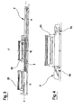
- the figures of the drawings relate to an apparatus for in-feeding and removing tile trucks to and from loading/unloading machines according to the present invention. It comprises a transport plane composed of balls 2, for supporting and removing at least one truck 20, as well as for moving the truck 20.
- the apparatus further comprises a motor 3, for moving the truck 20 along a longitudinal direction x, longitudinal reference means, predisposed for a positioning of the truck 20 along the longitudinal direction x, and transversal guide means 4, predisposed for positioning the truck 20 in a transversal direction y which is not parallel to the longitudinal direction x and for orienting the truck 20 about a vertical axis z.
- the ball transport plane 2 develops in the longitudinal direction x and comprises a first load section A for receiving and supporting at least one truck 20 arranged with any orientation with respect to a vertical axis z, an unloading section C from which the truck 20 can be removed, and a work section B, intermediate with respect to sections A and C, on which the tiles are loaded and unloaded to and from the truck 20.
- the truck 20 is in proximity of the tile loading/unloading machine and interacts with a mobile arm bearing a plurality of chucks predisposed to connect kinematically with the rollers defining the planes of the truck 20.
- the mobile arm is arranged laterally to the truck 20, which is positioned correctly, as will be better described herein below, by means of longitudinal reference means and the transversal guide means 4. With a displacement in a parallel direction to the longitudinal direction x the chucks supported by the mobile arm can insert into the rollers of the truck 20 and rotate the rollers. Thus the tiles are transferred, either to be loaded or unloaded, with respect to the truck 20.
- the transversal guide means 4 are passive and comprise a vertical-axis plurality of rollers 8 projecting at least partially above the ball transport plane 2.
- the rollers 8 are arranged over at least a portion of two longitudinal sides of the ball transport plane 2 between the loading section A and the work section B, and are separated, in a parallel direction to the transversal direction y, by a decreasing distance along the longitudinal direction x in a direction of movement of the truck 20, from the loading section a to the unloading section C.
- the rollers 8 of the transversal guide means 4 define a funnel-shaped tract along the pathway followed by the truck 20 on the ball transport plane 2.
- the function of this funnel-shaped tract is to guarantee a correct positioning of the truck 20 in a parallel direction to the transversal direction y and about the vertical axis z.
- the truck 20 is deposited on the loading section A in no precise orientation, for example by manually-operated fork trucks. From the loading section A, the truck then translates towards the work section B, pushed by pushing organs 13 activated by a motor 3.
- the truck 20 While translating from the loading section A to the work section B, the truck 20 enters into contact with the rollers 8. As it is supported on a ball transport plane, the truck 20 is mobile with respect to the ball transport plane in both a longitudinal direction x, and in transversal direction y. Bumping and/or sliding against the rollers 8, the truck rotates about the vertical axis z and translates along the transversal direction y, arranging itself in a predetermined position according to the arrangement of the rollers 8.
- the longitudinal reference means comprise at least two reference elements 9a and 9b, located on opposite sides of the work section B.
- One of the elements 9a is in a fixed position and swings freely in order to act only upon movements of the truck 20 going in an opposite direction to the advancement direction from the loading section A to the work section B.
- the second of the reference elements 9b is pneumatically activated on command to push the truck 20 against the first of the reference elements 9a.
- the ball transport plane 2 further comprises means for pre-orienting, arranged at the loading section A, which are predisposed at least partially to position the newly-loaded truck 20 with respect to the vertical axis z.
- the means for pre-orienting can comprise four hydraulic cylinders 11, arranged in pairs on opposite sides to the axis x, operating in a parallel direction to the transversal direction y and mobile between a ready position, in which they are not in contact with the truck 20, and a work position, in which they are in contact with the truck 20.
- the hydraulic cylinders 11 are arranged in such a way that the lateral pressure they exert on the truck 20 causes a rotation of the truck 20 about the vertical axis z.
- the hydraulic cylinders 11 are arranged at the comers of a rectangle which is symmetrical with respect to the longitudinal direction x.
- the apparatus for in-feeding and removing tile trucks to and from loading/unloading machines offers important advantages. Firstly it functions simply and precisely and adapts to any type of loading/unloading machine. It correctly positions trucks without any need for the trucks to be loaded with any initial orientation, freeing fork truck operators from any need to "park" the fork truck in any special way; this makes the movement of the tile trucks much more rapid. Also, the tile truck is positioned with no awkward direct contact with surfaces or other reference means on the part of the fork truck, which prevents bumping and scraping of the tile truck and of the tiles arranged thereon.
Landscapes
- Engineering & Computer Science (AREA)
- Mechanical Engineering (AREA)
- Loading Or Unloading Of Vehicles (AREA)
- Infusion, Injection, And Reservoir Apparatuses (AREA)
- Conveying And Assembling Of Building Elements In Situ (AREA)
- Devices For Post-Treatments, Processing, Supply, Discharge, And Other Processes (AREA)
Claims (5)
- Dispositif de chargement et d'extraction de camions de tuiles vers et des machines de chargement/déchargement en correspondance desquelles les camions de tuiles disposés dans une position prédéterminée par rapport à une machine de chargement/déchargement sont chargés et déchargés, le dispositif comprenant un plan de transport à sphères (2) pour supporter et recevoir au moins un camion de tuiles (20), et pour déplacer ce dernier; un moteur (3) prédisposé pour déplacer le camion de tuiles (20) le long d'une direction longitudinale horizontale (x); caractérisé en ce que ledit dispositif comprend des moyens de référence longitudinaux (9a, 9b) prédisposés pour positionner le camion de tuiles (20) le long de la direction longitudinale (x); un guide transversal (4) prédisposé pour positionner le camion de tuiles (20) le long d'une direction transversale (y) qui n'est pas parallèle à la direction longitudinale (x) et pour orienter le camion de tuiles (20) autour d'un axe vertical (z).
- Dispositif selon la revendication 1, caractérisé en ce que le plan de transport à sphères (2) se développe le long de la direction longitudinale (x) et comprend une section de chargement (A), pour recevoir au moins un camion de tuiles (20) disposé dans n'importe quelle orientation par rapport à l'axe vertical (z), une section de déchargement (C) de laquelle le camion de tuiles (20) peut être prélevé, et une section de travail (B), intermédiaire de la section de chargement (A) et de la section de déchargement (C), dans laquelle les tuiles sont chargées ou déchargées sur ou du camion de tuiles (20).
- Dispositif selon la revendication 1, caractérisé en ce que le guide transversal (4) est passif et comprend une pluralité de rouleaux à axe vertical (8) qui sont au moins partiellement saillants au-dessus du plan de transport à sphères (2), les rouleaux (8) étant disposés le long d'au moins une partie de deux côtés longitudinaux du plan de transport à sphères (2) entre la section de chargement (A) et la section de travail (B), les rouleaux (8) étant séparés dans une direction parallèle à la direction transversale (y) par des distances décroissantes le long de la direction longitudinale (x) dans une direction dans laquelle le camion de tuiles (20) se déplace, de la section de chargement (A) à la section de déchargement (B).
- Dispositif selon la revendication 1, caractérisé en ce que les moyens de référence longitudinaux comprennent au moins deux éléments de référence (9a, 9b), disposés sur des côtés opposés de la section de travail (B); un premier élément de référence (9a) des au moins deux éléments de référence (9a, 9b) étant dans une position fixe et pouvant s'incliner librement de manière à agir seulement sur les déplacements du camion de tuiles (20), lesquels déplacements s'effectuent dans une direction opposée à une direction d'avancée du camion de tuiles (20) de la section de chargement (A) à la section de travail (B); un second élément de référence (9b) des au moins deux éléments de référence (9a, 9b) étant pneumatiquement activé sur commande de manière à pousser le camion de tuiles (20) contre le premier élément de référence (9a) de manière à bloquer le camion de tuiles (20) dans la section de travail (B).
- Dispositif selon la revendication 2, caractérisé en ce que le plan de transport à sphères (2) comprend des moyens de pré-orientation, disposés en correspondance de la section de chargement (A), prédisposés pour au moins partiellement orienter le camion de tuiles (20) par rapport à l'axe vertical (z) lorsque le camion de tuiles (20) est disposé dans la section de chargement (A), les moyens de pré-orientation comprenant quatre vérins hydrauliques (11) disposés par paires sur des côtés opposés par rapport à la direction longitudinale (x), et opérant dans une direction parallèle à la direction transversale (y), et étant mobiles entre une position d'attente, dans laquelle il n'y a aucun contact avec le camion de tuiles (20), et une position opérationnelle, dans laquelle il y a un contact avec le camion de tuiles (20).
Applications Claiming Priority (2)
| Application Number | Priority Date | Filing Date | Title |
|---|---|---|---|
| IT000274A ITMO20030274A1 (it) | 2003-10-07 | 2003-10-07 | Apparecchiatura per l'alimentazione ed il prelevamento |
| ITMO20030274 | 2003-10-07 |
Publications (2)
| Publication Number | Publication Date |
|---|---|
| EP1522511A1 EP1522511A1 (fr) | 2005-04-13 |
| EP1522511B1 true EP1522511B1 (fr) | 2006-11-22 |
Family
ID=34308132
Family Applications (1)
| Application Number | Title | Priority Date | Filing Date |
|---|---|---|---|
| EP04077632A Expired - Lifetime EP1522511B1 (fr) | 2003-10-07 | 2004-09-22 | Dispositif de chargement et d'extraction de camions des tuiles vers les/des machines du chargement et déchargement |
Country Status (5)
| Country | Link |
|---|---|
| EP (1) | EP1522511B1 (fr) |
| AT (1) | ATE346002T1 (fr) |
| DE (1) | DE602004003320T2 (fr) |
| ES (1) | ES2274381T3 (fr) |
| IT (1) | ITMO20030274A1 (fr) |
Families Citing this family (4)
| Publication number | Priority date | Publication date | Assignee | Title |
|---|---|---|---|---|
| ITMO20050206A1 (it) * | 2005-08-05 | 2007-02-06 | Kemac S P A | Apparato a carrelli traslabili per il posizionamento e lo scarico dei materiali in lavorazione in macchine utensili a getto d'acqua |
| CN102502223B (zh) * | 2011-09-30 | 2013-12-11 | 广东宏威陶瓷实业有限公司 | 一种校位装置 |
| CN102530461B (zh) * | 2012-01-19 | 2013-07-03 | 金陵科技学院 | 一种组合式立体仓库及其控制方法 |
| CN103523504B (zh) * | 2013-10-29 | 2015-11-11 | 福建省信捷机械有限公司 | 一种西瓦调头机 |
Family Cites Families (4)
| Publication number | Priority date | Publication date | Assignee | Title |
|---|---|---|---|---|
| US2986262A (en) * | 1958-06-25 | 1961-05-30 | Bulletin Company | Bundle aligning and spacing apparatus |
| US3679043A (en) * | 1971-04-13 | 1972-07-25 | Webb Co Jervis B | Roller transfer conveyor |
| SE392704B (sv) * | 1974-07-08 | 1977-04-18 | Esab Hebe Ab | Forfarande och anordning for stegvis forflyttning av ett flertal stora platar av olika storlek |
| FR2673860A1 (fr) * | 1991-03-15 | 1992-09-18 | Lucas Sa | Table a billes motorisees a mouvements croises pour le triage orthogonal de charges plates. |
-
2003
- 2003-10-07 IT IT000274A patent/ITMO20030274A1/it unknown
-
2004
- 2004-09-22 DE DE602004003320T patent/DE602004003320T2/de not_active Expired - Lifetime
- 2004-09-22 EP EP04077632A patent/EP1522511B1/fr not_active Expired - Lifetime
- 2004-09-22 ES ES04077632T patent/ES2274381T3/es not_active Expired - Lifetime
- 2004-09-22 AT AT04077632T patent/ATE346002T1/de not_active IP Right Cessation
Also Published As
| Publication number | Publication date |
|---|---|
| ES2274381T3 (es) | 2007-05-16 |
| EP1522511A1 (fr) | 2005-04-13 |
| DE602004003320D1 (de) | 2007-01-04 |
| ATE346002T1 (de) | 2006-12-15 |
| DE602004003320T2 (de) | 2007-05-24 |
| ITMO20030274A1 (it) | 2005-04-08 |
Similar Documents
| Publication | Publication Date | Title |
|---|---|---|
| CN107878989B (zh) | 一种仓储自动取料机 | |
| CN107667061B (zh) | 用于将件货存入货架中的方法和仓库系统 | |
| EP3748081B1 (fr) | Wagon de chemin de fer pour mouvement de traverses et véhicule de chemin de fer avec un tel wagon de chemin | |
| CN107840059B (zh) | 一种双向仓储自动取料机 | |
| KR102073778B1 (ko) | 팰릿 반송 장치 | |
| GB2189209A (en) | Loading cartons on to pallets | |
| CN117324967B (zh) | 重载生产线 | |
| EP0309430B1 (fr) | Appareil de manipulation | |
| US4950128A (en) | Automatic loading unit for sheet units onto machines equipped with a conveyor | |
| US12128520B2 (en) | Production cell with workpiece return | |
| CN117735273A (zh) | 一种轻型装车系统 | |
| EP1522511A1 (fr) | Dispositif de chargement et d'extraction de camions des tuiles vers les/des machines du chargement et déchargement | |
| CN217807011U (zh) | 一种自动拆码垛装卸车 | |
| JPH1045257A (ja) | 貨物取り扱い装置 | |
| JPH05208731A (ja) | コンテナ内の荷役装置 | |
| JP4265460B2 (ja) | 無人搬送車による部品供給装置 | |
| US2741371A (en) | Pallet lifter | |
| CN114655658A (zh) | 一种自动拆码垛装卸车 | |
| KR100863432B1 (ko) | 팔레트 이송용 셔틀장치 | |
| JP3612806B2 (ja) | 巻取ロール縦積みパレタイザ及びパレットへの巻取ロール縦積み方法 | |
| JPS61226449A (ja) | プレス部品の積込装置 | |
| US5797479A (en) | Loading/unloading method and apparatus for a crane-assisted storage | |
| CN119551419B (zh) | 搬运输送系统 | |
| CN114162573B (zh) | 具有卸车摆臂的物料装车装置 | |
| CN121180913B (zh) | 一种仓储管理用多层式搬运车 |
Legal Events
| Date | Code | Title | Description |
|---|---|---|---|
| PUAI | Public reference made under article 153(3) epc to a published international application that has entered the european phase |
Free format text: ORIGINAL CODE: 0009012 |
|
| AK | Designated contracting states |
Kind code of ref document: A1 Designated state(s): AT BE BG CH CY CZ DE DK EE ES FI FR GB GR HU IE IT LI LU MC NL PL PT RO SE SI SK TR |
|
| AX | Request for extension of the european patent |
Extension state: AL HR LT LV MK |
|
| 17P | Request for examination filed |
Effective date: 20050915 |
|
| RAP1 | Party data changed (applicant data changed or rights of an application transferred) |
Owner name: KEMAC S.P.A. |
|
| AKX | Designation fees paid |
Designated state(s): AT BE BG CH CY CZ DE DK EE ES FI FR GB GR HU IE IT LI LU MC NL PL PT RO SE SI SK TR |
|
| GRAP | Despatch of communication of intention to grant a patent |
Free format text: ORIGINAL CODE: EPIDOSNIGR1 |
|
| GRAS | Grant fee paid |
Free format text: ORIGINAL CODE: EPIDOSNIGR3 |
|
| GRAA | (expected) grant |
Free format text: ORIGINAL CODE: 0009210 |
|
| AK | Designated contracting states |
Kind code of ref document: B1 Designated state(s): AT BE BG CH CY CZ DE DK EE ES FI FR GB GR HU IE IT LI LU MC NL PL PT RO SE SI SK TR |
|
| PG25 | Lapsed in a contracting state [announced via postgrant information from national office to epo] |
Ref country code: IT Free format text: LAPSE BECAUSE OF FAILURE TO SUBMIT A TRANSLATION OF THE DESCRIPTION OR TO PAY THE FEE WITHIN THE PRESCRIBED TIME-LIMIT;WARNING: LAPSES OF ITALIAN PATENTS WITH EFFECTIVE DATE BEFORE 2007 MAY HAVE OCCURRED AT ANY TIME BEFORE 2007. THE CORRECT EFFECTIVE DATE MAY BE DIFFERENT FROM THE ONE RECORDED. Effective date: 20061122 Ref country code: AT Free format text: LAPSE BECAUSE OF FAILURE TO SUBMIT A TRANSLATION OF THE DESCRIPTION OR TO PAY THE FEE WITHIN THE PRESCRIBED TIME-LIMIT Effective date: 20061122 Ref country code: RO Free format text: LAPSE BECAUSE OF FAILURE TO SUBMIT A TRANSLATION OF THE DESCRIPTION OR TO PAY THE FEE WITHIN THE PRESCRIBED TIME-LIMIT Effective date: 20061122 Ref country code: LI Free format text: LAPSE BECAUSE OF FAILURE TO SUBMIT A TRANSLATION OF THE DESCRIPTION OR TO PAY THE FEE WITHIN THE PRESCRIBED TIME-LIMIT Effective date: 20061122 Ref country code: BE Free format text: LAPSE BECAUSE OF FAILURE TO SUBMIT A TRANSLATION OF THE DESCRIPTION OR TO PAY THE FEE WITHIN THE PRESCRIBED TIME-LIMIT Effective date: 20061122 Ref country code: FI Free format text: LAPSE BECAUSE OF FAILURE TO SUBMIT A TRANSLATION OF THE DESCRIPTION OR TO PAY THE FEE WITHIN THE PRESCRIBED TIME-LIMIT Effective date: 20061122 Ref country code: CH Free format text: LAPSE BECAUSE OF FAILURE TO SUBMIT A TRANSLATION OF THE DESCRIPTION OR TO PAY THE FEE WITHIN THE PRESCRIBED TIME-LIMIT Effective date: 20061122 Ref country code: SI Free format text: LAPSE BECAUSE OF FAILURE TO SUBMIT A TRANSLATION OF THE DESCRIPTION OR TO PAY THE FEE WITHIN THE PRESCRIBED TIME-LIMIT Effective date: 20061122 Ref country code: PL Free format text: LAPSE BECAUSE OF FAILURE TO SUBMIT A TRANSLATION OF THE DESCRIPTION OR TO PAY THE FEE WITHIN THE PRESCRIBED TIME-LIMIT Effective date: 20061122 Ref country code: NL Free format text: LAPSE BECAUSE OF FAILURE TO SUBMIT A TRANSLATION OF THE DESCRIPTION OR TO PAY THE FEE WITHIN THE PRESCRIBED TIME-LIMIT Effective date: 20061122 Ref country code: CZ Free format text: LAPSE BECAUSE OF FAILURE TO SUBMIT A TRANSLATION OF THE DESCRIPTION OR TO PAY THE FEE WITHIN THE PRESCRIBED TIME-LIMIT Effective date: 20061122 Ref country code: SK Free format text: LAPSE BECAUSE OF FAILURE TO SUBMIT A TRANSLATION OF THE DESCRIPTION OR TO PAY THE FEE WITHIN THE PRESCRIBED TIME-LIMIT Effective date: 20061122 |
|
| REG | Reference to a national code |
Ref country code: GB Ref legal event code: FG4D |
|
| REG | Reference to a national code |
Ref country code: CH Ref legal event code: EP |
|
| REG | Reference to a national code |
Ref country code: IE Ref legal event code: FG4D |
|
| REF | Corresponds to: |
Ref document number: 602004003320 Country of ref document: DE Date of ref document: 20070104 Kind code of ref document: P |
|
| PG25 | Lapsed in a contracting state [announced via postgrant information from national office to epo] |
Ref country code: BG Free format text: LAPSE BECAUSE OF FAILURE TO SUBMIT A TRANSLATION OF THE DESCRIPTION OR TO PAY THE FEE WITHIN THE PRESCRIBED TIME-LIMIT Effective date: 20070222 Ref country code: DK Free format text: LAPSE BECAUSE OF FAILURE TO SUBMIT A TRANSLATION OF THE DESCRIPTION OR TO PAY THE FEE WITHIN THE PRESCRIBED TIME-LIMIT Effective date: 20070222 Ref country code: SE Free format text: LAPSE BECAUSE OF FAILURE TO SUBMIT A TRANSLATION OF THE DESCRIPTION OR TO PAY THE FEE WITHIN THE PRESCRIBED TIME-LIMIT Effective date: 20070222 |
|
| PG25 | Lapsed in a contracting state [announced via postgrant information from national office to epo] |
Ref country code: PT Free format text: LAPSE BECAUSE OF FAILURE TO SUBMIT A TRANSLATION OF THE DESCRIPTION OR TO PAY THE FEE WITHIN THE PRESCRIBED TIME-LIMIT Effective date: 20070423 |
|
| NLV1 | Nl: lapsed or annulled due to failure to fulfill the requirements of art. 29p and 29m of the patents act | ||
| REG | Reference to a national code |
Ref country code: ES Ref legal event code: FG2A Ref document number: 2274381 Country of ref document: ES Kind code of ref document: T3 |
|
| REG | Reference to a national code |
Ref country code: CH Ref legal event code: PL |
|
| EN | Fr: translation not filed | ||
| PLBE | No opposition filed within time limit |
Free format text: ORIGINAL CODE: 0009261 |
|
| STAA | Information on the status of an ep patent application or granted ep patent |
Free format text: STATUS: NO OPPOSITION FILED WITHIN TIME LIMIT |
|
| 26N | No opposition filed |
Effective date: 20070823 |
|
| PG25 | Lapsed in a contracting state [announced via postgrant information from national office to epo] |
Ref country code: MC Free format text: LAPSE BECAUSE OF NON-PAYMENT OF DUE FEES Effective date: 20070930 Ref country code: FR Free format text: LAPSE BECAUSE OF FAILURE TO SUBMIT A TRANSLATION OF THE DESCRIPTION OR TO PAY THE FEE WITHIN THE PRESCRIBED TIME-LIMIT Effective date: 20070713 Ref country code: GR Free format text: LAPSE BECAUSE OF FAILURE TO SUBMIT A TRANSLATION OF THE DESCRIPTION OR TO PAY THE FEE WITHIN THE PRESCRIBED TIME-LIMIT Effective date: 20070223 |
|
| PG25 | Lapsed in a contracting state [announced via postgrant information from national office to epo] |
Ref country code: IE Free format text: LAPSE BECAUSE OF NON-PAYMENT OF DUE FEES Effective date: 20070924 |
|
| PG25 | Lapsed in a contracting state [announced via postgrant information from national office to epo] |
Ref country code: FR Free format text: LAPSE BECAUSE OF FAILURE TO SUBMIT A TRANSLATION OF THE DESCRIPTION OR TO PAY THE FEE WITHIN THE PRESCRIBED TIME-LIMIT Effective date: 20061122 |
|
| PG25 | Lapsed in a contracting state [announced via postgrant information from national office to epo] |
Ref country code: EE Free format text: LAPSE BECAUSE OF FAILURE TO SUBMIT A TRANSLATION OF THE DESCRIPTION OR TO PAY THE FEE WITHIN THE PRESCRIBED TIME-LIMIT Effective date: 20061122 |
|
| GBPC | Gb: european patent ceased through non-payment of renewal fee |
Effective date: 20080922 |
|
| PG25 | Lapsed in a contracting state [announced via postgrant information from national office to epo] |
Ref country code: LU Free format text: LAPSE BECAUSE OF NON-PAYMENT OF DUE FEES Effective date: 20070922 Ref country code: CY Free format text: LAPSE BECAUSE OF FAILURE TO SUBMIT A TRANSLATION OF THE DESCRIPTION OR TO PAY THE FEE WITHIN THE PRESCRIBED TIME-LIMIT Effective date: 20061122 |
|
| PG25 | Lapsed in a contracting state [announced via postgrant information from national office to epo] |
Ref country code: TR Free format text: LAPSE BECAUSE OF FAILURE TO SUBMIT A TRANSLATION OF THE DESCRIPTION OR TO PAY THE FEE WITHIN THE PRESCRIBED TIME-LIMIT Effective date: 20061122 Ref country code: HU Free format text: LAPSE BECAUSE OF FAILURE TO SUBMIT A TRANSLATION OF THE DESCRIPTION OR TO PAY THE FEE WITHIN THE PRESCRIBED TIME-LIMIT Effective date: 20070523 |
|
| PG25 | Lapsed in a contracting state [announced via postgrant information from national office to epo] |
Ref country code: GB Free format text: LAPSE BECAUSE OF NON-PAYMENT OF DUE FEES Effective date: 20080922 |
|
| PGFP | Annual fee paid to national office [announced via postgrant information from national office to epo] |
Ref country code: DE Payment date: 20230822 Year of fee payment: 20 |
|
| PGFP | Annual fee paid to national office [announced via postgrant information from national office to epo] |
Ref country code: ES Payment date: 20231002 Year of fee payment: 20 |
|
| REG | Reference to a national code |
Ref country code: DE Ref legal event code: R071 Ref document number: 602004003320 Country of ref document: DE |
|
| REG | Reference to a national code |
Ref country code: ES Ref legal event code: FD2A Effective date: 20240927 |
|
| PG25 | Lapsed in a contracting state [announced via postgrant information from national office to epo] |
Ref country code: ES Free format text: LAPSE BECAUSE OF EXPIRATION OF PROTECTION Effective date: 20240923 |
|
| PG25 | Lapsed in a contracting state [announced via postgrant information from national office to epo] |
Ref country code: ES Free format text: LAPSE BECAUSE OF EXPIRATION OF PROTECTION Effective date: 20240923 |