EP1522525B1 - Dispositif et puits pour le traitement décentralisé de l'eau et procédé correspondant - Google Patents
Dispositif et puits pour le traitement décentralisé de l'eau et procédé correspondant Download PDFInfo
- Publication number
- EP1522525B1 EP1522525B1 EP04104931A EP04104931A EP1522525B1 EP 1522525 B1 EP1522525 B1 EP 1522525B1 EP 04104931 A EP04104931 A EP 04104931A EP 04104931 A EP04104931 A EP 04104931A EP 1522525 B1 EP1522525 B1 EP 1522525B1
- Authority
- EP
- European Patent Office
- Prior art keywords
- shaft
- ion exchanger
- water
- plates
- segments
- Prior art date
- Legal status (The legal status is an assumption and is not a legal conclusion. Google has not performed a legal analysis and makes no representation as to the accuracy of the status listed.)
- Expired - Lifetime
Links
- XLYOFNOQVPJJNP-UHFFFAOYSA-N water Substances O XLYOFNOQVPJJNP-UHFFFAOYSA-N 0.000 title claims abstract description 59
- 238000000034 method Methods 0.000 title claims description 18
- 229910001385 heavy metal Inorganic materials 0.000 claims abstract description 20
- 125000006850 spacer group Chemical group 0.000 claims abstract description 11
- 230000001172 regenerating effect Effects 0.000 claims abstract description 9
- 229910021536 Zeolite Inorganic materials 0.000 claims abstract description 4
- HNPSIPDUKPIQMN-UHFFFAOYSA-N dioxosilane;oxo(oxoalumanyloxy)alumane Chemical compound O=[Si]=O.O=[Al]O[Al]=O HNPSIPDUKPIQMN-UHFFFAOYSA-N 0.000 claims abstract description 4
- 239000010457 zeolite Substances 0.000 claims abstract description 4
- 150000002500 ions Chemical class 0.000 claims description 46
- 239000007788 liquid Substances 0.000 claims description 20
- FAPWRFPIFSIZLT-UHFFFAOYSA-M Sodium chloride Chemical compound [Na+].[Cl-] FAPWRFPIFSIZLT-UHFFFAOYSA-M 0.000 claims description 8
- 238000000926 separation method Methods 0.000 claims description 8
- 230000008595 infiltration Effects 0.000 claims description 7
- 238000001764 infiltration Methods 0.000 claims description 7
- 239000002245 particle Substances 0.000 claims description 7
- 239000003463 adsorbent Substances 0.000 claims description 6
- 238000009434 installation Methods 0.000 claims description 6
- JEWHCPOELGJVCB-UHFFFAOYSA-N aluminum;calcium;oxido-[oxido(oxo)silyl]oxy-oxosilane;potassium;sodium;tridecahydrate Chemical compound O.O.O.O.O.O.O.O.O.O.O.O.O.[Na].[Al].[K].[Ca].[O-][Si](=O)O[Si]([O-])=O JEWHCPOELGJVCB-UHFFFAOYSA-N 0.000 claims description 3
- JYIBXUUINYLWLR-UHFFFAOYSA-N aluminum;calcium;potassium;silicon;sodium;trihydrate Chemical compound O.O.O.[Na].[Al].[Si].[K].[Ca] JYIBXUUINYLWLR-UHFFFAOYSA-N 0.000 claims description 3
- 229910001603 clinoptilolite Inorganic materials 0.000 claims description 3
- 229910001743 phillipsite Inorganic materials 0.000 claims description 3
- 239000011780 sodium chloride Substances 0.000 claims description 3
- 238000007599 discharging Methods 0.000 claims 1
- 230000010412 perfusion Effects 0.000 claims 1
- 229910052710 silicon Inorganic materials 0.000 claims 1
- 239000010703 silicon Substances 0.000 claims 1
- 239000012530 fluid Substances 0.000 abstract description 3
- 239000008187 granular material Substances 0.000 abstract 1
- 238000004140 cleaning Methods 0.000 description 24
- 230000008929 regeneration Effects 0.000 description 20
- 238000011069 regeneration method Methods 0.000 description 20
- 239000003673 groundwater Substances 0.000 description 12
- 239000000463 material Substances 0.000 description 6
- 239000008213 purified water Substances 0.000 description 6
- 239000002689 soil Substances 0.000 description 5
- 238000010276 construction Methods 0.000 description 4
- 239000000356 contaminant Substances 0.000 description 4
- 229910052751 metal Inorganic materials 0.000 description 4
- 239000002184 metal Substances 0.000 description 4
- 229920001296 polysiloxane Polymers 0.000 description 4
- 238000007789 sealing Methods 0.000 description 4
- 239000000126 substance Substances 0.000 description 4
- RYGMFSIKBFXOCR-UHFFFAOYSA-N Copper Chemical compound [Cu] RYGMFSIKBFXOCR-UHFFFAOYSA-N 0.000 description 3
- HCHKCACWOHOZIP-UHFFFAOYSA-N Zinc Chemical compound [Zn] HCHKCACWOHOZIP-UHFFFAOYSA-N 0.000 description 3
- 229910052802 copper Inorganic materials 0.000 description 3
- 239000010949 copper Substances 0.000 description 3
- 229910052725 zinc Inorganic materials 0.000 description 3
- 239000011701 zinc Substances 0.000 description 3
- OKTJSMMVPCPJKN-UHFFFAOYSA-N Carbon Chemical compound [C] OKTJSMMVPCPJKN-UHFFFAOYSA-N 0.000 description 2
- 238000006243 chemical reaction Methods 0.000 description 2
- 238000011109 contamination Methods 0.000 description 2
- 238000013461 design Methods 0.000 description 2
- 239000003344 environmental pollutant Substances 0.000 description 2
- 238000011049 filling Methods 0.000 description 2
- 238000011010 flushing procedure Methods 0.000 description 2
- 239000012535 impurity Substances 0.000 description 2
- 239000011133 lead Substances 0.000 description 2
- 231100000719 pollutant Toxicity 0.000 description 2
- 238000000746 purification Methods 0.000 description 2
- 230000000717 retained effect Effects 0.000 description 2
- 238000004062 sedimentation Methods 0.000 description 2
- 239000010802 sludge Substances 0.000 description 2
- 229910001220 stainless steel Inorganic materials 0.000 description 2
- 239000010935 stainless steel Substances 0.000 description 2
- 239000002351 wastewater Substances 0.000 description 2
- 241000239290 Araneae Species 0.000 description 1
- 238000005299 abrasion Methods 0.000 description 1
- 238000010521 absorption reaction Methods 0.000 description 1
- 229910052782 aluminium Inorganic materials 0.000 description 1
- XAGFODPZIPBFFR-UHFFFAOYSA-N aluminium Chemical compound [Al] XAGFODPZIPBFFR-UHFFFAOYSA-N 0.000 description 1
- 230000015572 biosynthetic process Effects 0.000 description 1
- 239000003054 catalyst Substances 0.000 description 1
- 239000004568 cement Substances 0.000 description 1
- 238000011161 development Methods 0.000 description 1
- 230000018109 developmental process Effects 0.000 description 1
- 238000005516 engineering process Methods 0.000 description 1
- 238000001914 filtration Methods 0.000 description 1
- 238000003306 harvesting Methods 0.000 description 1
- 229910052500 inorganic mineral Inorganic materials 0.000 description 1
- 238000007689 inspection Methods 0.000 description 1
- 238000011835 investigation Methods 0.000 description 1
- 238000005342 ion exchange Methods 0.000 description 1
- 238000002386 leaching Methods 0.000 description 1
- 238000012423 maintenance Methods 0.000 description 1
- 230000014759 maintenance of location Effects 0.000 description 1
- 239000011707 mineral Substances 0.000 description 1
- 239000000203 mixture Substances 0.000 description 1
- 239000003921 oil Substances 0.000 description 1
- 238000005457 optimization Methods 0.000 description 1
- 125000005575 polycyclic aromatic hydrocarbon group Chemical group 0.000 description 1
- 239000011148 porous material Substances 0.000 description 1
- 230000002787 reinforcement Effects 0.000 description 1
- 239000010865 sewage Substances 0.000 description 1
- 238000012360 testing method Methods 0.000 description 1
- 238000005406 washing Methods 0.000 description 1
Images
Classifications
-
- E—FIXED CONSTRUCTIONS
- E03—WATER SUPPLY; SEWERAGE
- E03B—INSTALLATIONS OR METHODS FOR OBTAINING, COLLECTING, OR DISTRIBUTING WATER
- E03B3/00—Methods or installations for obtaining or collecting drinking water or tap water
- E03B3/02—Methods or installations for obtaining or collecting drinking water or tap water from rain-water
- E03B3/03—Special vessels for collecting or storing rain-water for use in the household, e.g. water-butts
-
- B—PERFORMING OPERATIONS; TRANSPORTING
- B01—PHYSICAL OR CHEMICAL PROCESSES OR APPARATUS IN GENERAL
- B01J—CHEMICAL OR PHYSICAL PROCESSES, e.g. CATALYSIS OR COLLOID CHEMISTRY; THEIR RELEVANT APPARATUS
- B01J47/00—Ion-exchange processes in general; Apparatus therefor
- B01J47/02—Column or bed processes
- B01J47/022—Column or bed processes characterised by the construction of the column or container
-
- B—PERFORMING OPERATIONS; TRANSPORTING
- B01—PHYSICAL OR CHEMICAL PROCESSES OR APPARATUS IN GENERAL
- B01J—CHEMICAL OR PHYSICAL PROCESSES, e.g. CATALYSIS OR COLLOID CHEMISTRY; THEIR RELEVANT APPARATUS
- B01J49/00—Regeneration or reactivation of ion-exchangers; Apparatus therefor
- B01J49/05—Regeneration or reactivation of ion-exchangers; Apparatus therefor of fixed beds
- B01J49/06—Regeneration or reactivation of ion-exchangers; Apparatus therefor of fixed beds containing cationic exchangers
-
- C—CHEMISTRY; METALLURGY
- C02—TREATMENT OF WATER, WASTE WATER, SEWAGE, OR SLUDGE
- C02F—TREATMENT OF WATER, WASTE WATER, SEWAGE, OR SLUDGE
- C02F1/00—Treatment of water, waste water, or sewage
- C02F1/42—Treatment of water, waste water, or sewage by ion-exchange
-
- E—FIXED CONSTRUCTIONS
- E03—WATER SUPPLY; SEWERAGE
- E03B—INSTALLATIONS OR METHODS FOR OBTAINING, COLLECTING, OR DISTRIBUTING WATER
- E03B3/00—Methods or installations for obtaining or collecting drinking water or tap water
- E03B3/02—Methods or installations for obtaining or collecting drinking water or tap water from rain-water
-
- C—CHEMISTRY; METALLURGY
- C02—TREATMENT OF WATER, WASTE WATER, SEWAGE, OR SLUDGE
- C02F—TREATMENT OF WATER, WASTE WATER, SEWAGE, OR SLUDGE
- C02F1/00—Treatment of water, waste water, or sewage
- C02F1/28—Treatment of water, waste water, or sewage by sorption
- C02F1/281—Treatment of water, waste water, or sewage by sorption using inorganic sorbents
-
- C—CHEMISTRY; METALLURGY
- C02—TREATMENT OF WATER, WASTE WATER, SEWAGE, OR SLUDGE
- C02F—TREATMENT OF WATER, WASTE WATER, SEWAGE, OR SLUDGE
- C02F2101/00—Nature of the contaminant
- C02F2101/10—Inorganic compounds
- C02F2101/20—Heavy metals or heavy metal compounds
-
- C—CHEMISTRY; METALLURGY
- C02—TREATMENT OF WATER, WASTE WATER, SEWAGE, OR SLUDGE
- C02F—TREATMENT OF WATER, WASTE WATER, SEWAGE, OR SLUDGE
- C02F2103/00—Nature of the water, waste water, sewage or sludge to be treated
- C02F2103/001—Runoff or storm water
-
- Y—GENERAL TAGGING OF NEW TECHNOLOGICAL DEVELOPMENTS; GENERAL TAGGING OF CROSS-SECTIONAL TECHNOLOGIES SPANNING OVER SEVERAL SECTIONS OF THE IPC; TECHNICAL SUBJECTS COVERED BY FORMER USPC CROSS-REFERENCE ART COLLECTIONS [XRACs] AND DIGESTS
- Y02—TECHNOLOGIES OR APPLICATIONS FOR MITIGATION OR ADAPTATION AGAINST CLIMATE CHANGE
- Y02A—TECHNOLOGIES FOR ADAPTATION TO CLIMATE CHANGE
- Y02A20/00—Water conservation; Efficient water supply; Efficient water use
- Y02A20/108—Rainwater harvesting
Definitions
- the present invention relates to a device, in particular a shaft installation for the decentralized treatment of water, in particular of rainwater, which has two spaced apart, a cavity-forming plates, wherein the cavity for introducing an ion exchanger and / or adsorbent material is provided, and a corresponding shaft and a method for treating water, in particular for reducing heavy metals in water, especially rainwater from roof drains.
- Another known plant is a collection filter system with external sludge trap and a collection filter.
- sludge trap submerged walls are arranged in the inlet and outlet, which allow the sedimentation of particles.
- the collection filter is provided with a plastic filter cartridge, which is mounted on a base with special inlet nozzle. This structure allows a flow through the filter medium in the upflow.
- DE 101 27 553 A1 shows a filter insert for a gully shaft, which is designed as a filter cartridge with an overflow.
- the filter cartridge consists of a cartridge wall and a base plate and is filled with a mixture of mineral substances with chemical admixtures. As a result, a road inlet is to be created in which fine and chemical contaminants can be retained.
- US 2001/0035371 A1 discloses a device for filtering roof drains.
- the device is connected under the earth's surface with a vertical drain pipe and used to remove heavy metals from roof sewers before they reach the groundwater or find reuse in any other way.
- Pick, V. et al. also describe a "Decentralized treatment of rainfall runoff from traffic areas in a multi-level mine".
- the pit used here consists of a settling pit, which is connected via an inlet to a filter shaft.
- Two gravel filter layers are placed in sieve baskets and two activated carbon layers in the filter shaft.
- the aim of the investigations carried out with the aid of the plant described was to determine the cleaning performance of the test facility for the relevant load parameters heavy metals and organic substances, to gain experience with their operating behavior and to obtain information on planning and operational optimization possibilities.
- a disadvantage of the known systems is that the filters are not regenerable on site. They have to be exchanged in a complex procedure.
- Another disadvantage is that the use of such systems requires the construction of new shaft structures. Existing drainage shafts can not be retrofitted.
- the object of the present invention is thus to realize a decentralized treatment of mechanically pre-cleaned roof and street drains and to be able to install the required device in standard shafts or existing drainage shafts.
- the maintenance of the device should be feasible on site to keep the large number of required decentralized facilities cost-effective.
- a device according to the invention for the decentralized treatment of water has two spaced, forming a cavity plates.
- the cavity is provided for introducing an ion exchanger and / or adsorbent material for reducing heavy metals in the water.
- the plates consist of several segments and are spaced apart from each other.
- the device is intended for installation in a shaft and is used for the decentralized treatment of rainwater from roof drains or parking or street drains.
- the device according to the invention can be dismantled and can thereby be introduced into an existing shaft and mounted within the shaft.
- the filling of the device with a granular ion exchanger and / or an adsorbent material with organic impurities within the shaft is easy to perform.
- the device is thus universally applicable and can be used in particular without major conversion measures in existing shafts and treatment be put into operation by water.
- the treated with the granular ion exchanger water is purified of heavy metals and can then be supplied to the groundwater, for example, by infiltration. Water contaminants, which are caused by flushing of zinc or copper roofs, but also of aluminum roofs by the release of heavy metals, can thereby be separated from the water.
- the purified water can then be discharged into the groundwater, fed to a rainwater harvest or introduced into a receiving water.
- the plates are connected to each other with a spacer.
- the cavity which is provided for the granular ion exchanger is formed.
- the plates consist of a lower and an upper plate. By the spacer, the upper plate is not lifted by the water pressure from the ion exchanger, but maintains a defined distance from the lower plate.
- the water to be purified or purified can flow in and out of the device through the sieve plate into the device.
- the device according to the invention is flowed through in particular in the orthogonal direction of the plate.
- the plate is mounted on a supporting structure, then the plate itself can be made relatively thin and still absorb the load of the granular ion exchanger.
- the support structure supports the plate and allows attachment of the individual segments to a defined position of the device and the individual segments to each other.
- the segments of the plate and the support structure are bolted together. As a result, the assembly of the device within a shaft is carried out quickly.
- the distance of the plates is adjustable.
- the distance of the plates advantageously corresponds to the height of the filled ion exchanger and is usually between 50 and 100 cm.
- the amount of ion exchanger required depends in particular on the roof area and the amount of rainfall.
- the distance of the plates by different spacers which are used in the device, adjustable. But it can also be a stepless or stepped adjustment of the distance between the plates with a correspondingly shaped spacer.
- the diameter of the device substantially corresponds to the diameter of the shaft provided for the installation.
- the shafts which are often composed of concrete rings or constructed monolithically, usually have standardized diameter. If the device is dimensioned according to these shaft diameters, then it can be used in a variety of existing or, of course, newly installed shafts.
- the device is laterally sealed in the shaft, in particular with silicone. There is thus no possibility for the water to flow past the device according to the invention between the shaft and the device and to reach the groundwater without being cleaned.
- a zeolite in particular a clinoptilolite or chabazith / phillipsite, has proven particularly advantageous as an ion exchanger.
- Such an ion exchanger achieves excellent results when cleaning copper or zinc roofs.
- the device can be introduced into the shaft through a manhole of the shaft and can be assembled thereon, it is very easy to retrofit existing wastewater shafts. Earthworks to open the shaft and to use the device, this is not required. The costs and assembly time are thereby significantly reduced. A wide use and a realization of a variety of decentralized cleaning devices is thereby possible.
- the device is installed in the shaft so that it flows through the upflow.
- the water is passed from bottom to top through the device according to the invention. Washed out impurities of the water thereby fall down and can be separated from the water and from the device easily.
- An inventive shaft has a device with the features and advantages described above.
- the device is arranged laterally sealed in the shaft. This ensures that water flows through the passage of the shaft exclusively through the device and the water is thereby completely cleaned.
- the sealing of the device in the shaft takes place for example by silicone, which is arranged between the device and the shaft.
- the device adapts almost completely to the inner shaft diameter, so that the silicone only has to bridge a narrow gap.
- the sealing can also take place by means of sealing rings, which are inserted between the device and the shaft interior.
- the device is arranged in the upper region of the shaft, a flow through the device in the upflow method is made possible.
- the water to be purified is fed to the bottom of the shaft and passes from bottom to top through the device.
- a suction device is arranged within the shaft and below the device.
- the suction device is used in the case of a regeneration of the ion exchanger with a regeneration liquid for sucking this regeneration liquid. This prevents the regeneration liquid from entering the purified water and thus the groundwater. In addition, it may optionally be used to dispose of the separated particles.
- Manholes usually have a manhole, which is reduced in diameter compared to the rest of the shaft. It is used by service personnel in the manhole to carry out inspections.
- the device according to the invention is designed so that it can be introduced through the manhole of the shaft into the shaft, assembled in the shaft and filled with the ion exchanger.
- the construction of the device is therefore adapted to the present dimensions of the shaft or the manhole in the shaft. For subsequent installation of the device in the shaft, it is therefore not necessary to open the shaft completely. Conversion measures on the shaft to install the device need not be performed.
- the device can therefore be retrofitted in conventional wells.
- a drainage device for draining the cleaned water is arranged on the shaft.
- the drain device may be a trench. But it is also possible and often even more advantageous if the purified Water is discharged directly into the groundwater, a body of water or a domestic water connection.
- water is treated with a device and a shaft, in particular for reducing heavy metals, which are located, for example, in rainwater from roof drains.
- an ion exchanger which is located in the device in the shaft, is regenerated after a certain period of use by a regeneration fluid being flowed through the device.
- the device is not removed from the shaft, but is still in the shaft during regeneration.
- By flowing through the device with regenerating the ion exchanger is cleaned of the sorbed heavy metals therein and is then again for cleaning tasks of contaminated water available.
- the regeneration is very easy to perform and can therefore be done so often without much effort that the functionality of the ion exchanger is fully retained.
- regeneration liquid is sucked out below the device in the shaft.
- the regeneration liquid can be re-flowed from top to bottom through the device after suction. It can be used several times and this makes the ion exchanger particularly cost-effective to clean.
- a new or purified regeneration liquid can be used to make the cleaning process even more effective.
- a regeneration liquid in particular a saline solution has proven to be advantageous.
- a saline solution is inexpensive and allows a very effective cleaning of the ion exchanger.
- regenerating liquid is passed through the device several times, in particular two to three times, in order to regenerate the ion exchanger, excellent purification of the ion exchanger is achieved.
- the regeneration liquid is advantageously always renewed to ensure the absorption capacity for the heavy metal ions.
- the ion exchanger can also be rinsed with clean water to clean it of residues.
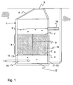
- a shaft 1 is shown schematically.
- the shaft 1 consists for example of concrete rings, which are stacked or made of a monolithic manhole and is located completely in the bottom 2.
- the shaft 2 For a reliable cleaning of the entire incoming water, the shaft 2 must be waterproof to the outside.
- the actual shaft area in the present embodiment consists of cylindrical ring segments 3, the end of the shaft is made of a conical ring segment 4 is formed.
- the conical ring segment 4 has at its one end a manhole 5, which is usually closed with a lid, but can be opened when needed by service personnel.
- a preferably made of stainless steel cleaning device 6 is arranged.
- the cleaning device 6 consists of an upper sieve plate 7 and a lower sieve plate 8.
- the two sieve plates 7, 8 are connected to a spacer 9 with each other.
- a granular ion exchanger 10 is arranged between the sieve plates 7 and 8, a granular ion exchanger 10 is arranged.
- the ion exchanger 10 is a zeolite, in particular a clinoptilolite or a chabazith / phillipsite.
- the material of the ion exchanger is filled in defined grits, for example greater than 0.7 mm between the sieve plates 7 and 8.
- it is pretreated, for example, with a sodium chloride solution. This increases the ion exchange capacity for heavy metal ions such as zinc, copper or lead.
- the pretreatment can be done before filling in the cleaning device.
- the ion exchanger is rinsed with the NaCl solution for this purpose.
- the cleaning device 6 is sealed relative to the shaft 1 by means of a seal 11. It may be a silicone strip which has been injected into the intermediate space between the device 6 and the shaft 1 or, for example, also a sealing ring which has been installed during installation between the cleaning device 6 and the shaft.
- a height of the device 6 is usually from about 50 to 100 cm with a diameter of the shaft 1 of about also 100 cm. Particularly advantageous in this cleaning device 6 is that the entire cross section of the shaft 1 is available for the purification of the water.
- a schematically illustrated separation unit 12 is arranged in the present embodiment.
- particles accumulate. From the separation unit 12, they can be removed from the separation unit 12 with a suction device, for example a vacuum pump, which is connected to a suction tube 13. In normal operation, the suction tube 13 is completed.
- a suction device for example a vacuum pump
- the suction tube 13 is used according to the present invention mainly for carrying out a regeneration process of the ion exchanger 10.
- regeneration liquid is flowed through from above through the cleaning device 6 and makes the ion exchanger resumable for heavy metal ions.
- the regeneration liquid and possibly a rinsing liquid, e.g. clear water, are sucked through the suction tube 13 from the shaft 1 and can be disposed of separately.
- a rinsing liquid e.g. clear water
- a feed tube 15 is integrated. About the feed pipe 15, the waste water to the shaft 1 and the cleaning device 6 is fed.
- the supply pipe 15 opens tangentially into the separation unit 12. Since the filter system could fail hydraulically in heavy rain events above the design rain, an emergency overflow not shown is often provided so that the water can get directly into a trench or a water drain 16.
- the polluted water supplied via the supply pipe 15 flows from bottom to top through the cleaning device 6 and after a certain water level has been reached in a pipe or a water drain 16.
- the water drain 16 can either deliver the purified water into the groundwater or an open water.
- the water can also be used in the home, for example, for toilet flushing or washing, for which the water drain 16 are connected to the domestic water system.
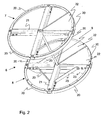
- FIG. 2 shows an example of a cleaning device 6, in perspective view.
- the upper sieve plate 7 and the lower sieve plate 8 are kept spaced apart with the spacer 9.
- the spacer 9 is a rod which is arranged in the center of the two screen plates 7 and 8 and is connected to the screen plates 7 and 8 at its respective end, for example with a screw connection.
- the upper screen plate 7 has a supporting structure of four circular segments 20 and a support cross 21. On the support structure segments 22 are attached, of which in the present illustration, for clarity, only one segment 22 is shown. In the case of the complete device 6, eight such segments 22 are arranged on the upper screen plate 7, so that the screen plate 7 is formed from the segments 22.
- the circle segments 20, the spider 21 and the segments 22 are bolted together. This makes it possible that they are inserted through the manhole 5 in the shaft 1 and mounted within the shaft 1.
- the sieve segments 22 are preferably made of a stainless steel screen with openings, which on the one hand let pass the water and on the other hand hold back the ion exchanger.
- the mesh size of the screen surface is therefore selected according to the ion exchanger 10 used. For example, a mesh size of less than 0.7 mm is selected.
- the lower screen plate 8 is constructed as well as the upper screen plate 7. Since it weighs on the weight of the ion exchanger 10, it has additional Reinforcements 23 which support the support structure and the Siebsegmente 22.
- the present invention is not limited to the illustrated embodiments.
- the cleaning of rainwater draining from roads or car parks can be cleaned by introducing adsorbing material from organic contaminants such as those derived from vehicles.
- the adsorbent material can additionally or alternatively be introduced into the device according to the invention to the ion exchanger.
Landscapes
- Engineering & Computer Science (AREA)
- Chemical & Material Sciences (AREA)
- Water Supply & Treatment (AREA)
- Life Sciences & Earth Sciences (AREA)
- Hydrology & Water Resources (AREA)
- Environmental & Geological Engineering (AREA)
- Organic Chemistry (AREA)
- Public Health (AREA)
- Health & Medical Sciences (AREA)
- Chemical Kinetics & Catalysis (AREA)
- Water Treatment By Sorption (AREA)
- Treatment Of Water By Ion Exchange (AREA)
- Chemical Treatment Of Metals (AREA)
Claims (24)
- Dispositif destiné à l'incorporation dans un puits (1) pour le traitement de l'eau, particulièrement de l'eau de pluie, lequel comporte deux plaques (7, 8) distancées l'un de l'autre et formant un espace vide, sachant que ledit espace vide est rempli au moins partiellement d'un échangeur d'ions (10) et/ou d'une matière absorbante, caractérisé en ce que les plaques (7, 8) se composent de plusieurs segments (20, 21, 22, 23) et qu'elles sont fixées à une certaine distance les unes des autres.
- Dispositif selon la revendication 1, caractérisé en ce que les plaques (7, 8) sont assemblées les unes aux autres avec une cale d'espacement (9).
- Dispositif selon l'une quelconque ou plusieurs des revendications précédentes, caractérisé en ce que l'une des plaques (7, 8) au moins est une plaque perforée.
- Dispositif selon l'une quelconque ou plusieurs des revendications précédentes, caractérisé en ce que la plaque (7, 8) est fixée sur une construction porteuse (21, 22, 23).
- Dispositif selon l'une quelconque ou plusieurs des revendications précédentes, caractérisé en ce que les segments perforés (22) de la plaque (7, 8) et la construction porteuse (21, 22, 23) sont boulonnés l'un à l'autre.
- Dispositif selon l'une quelconque ou plusieurs des revendications précédentes, caractérisé en ce que la distance entre les plaques (7, 8) correspond à la hauteur de l'échangeur d'ions versé et qu'elle est ajustable de préférence entre 50 cm et 100 cm de l'une à l'autre.
- Dispositif selon l'une quelconque ou plusieurs des revendications précédentes, caractérisé en ce que la distance entre les plaques (7, 8) est ajustable au moyen de cales d'espacement (9) différentes.
- Dispositif selon l'une quelconque ou plusieurs des revendications précédentes, caractérisé en ce que le diamètre du dispositif (6), particulièrement des plaques (7, 8), correspond essentiellement au diamètre du puits (1) prévu pour l'incorporation.
- Dispositif selon l'une quelconque ou plusieurs des revendications précédentes, caractérisé en ce que l'échangeur d'ions (10) se présente sous forme granulée.
- Dispositif selon l'une quelconque ou plusieurs des revendications précédentes, caractérisé en ce que l'échangeur d'ions (10) est un zéolithe, particulièrement un clinoptilolithe ou un chabasithe/phillipsite.
- Puis avec un dispositif selon les revendications précédentes, caractérisé en ce que le dispositif (6) est disposé dans le puits (1) latéralement, étanchéifié particulièrement au silicone, et qu'il est rempli au moins partiellement d'un échangeur d'ions (10) et/ou d'une matière absorbante.
- Puits selon la revendication précédente, caractérisé en que le dispositif (6) est implanté entre l'entrée et la sortie du puits (1) pour sa traversée selon la méthode du courant ascendant.
- Puits selon la revendication précédente, caractérisé en qu'une unité de séparation (12) des particules est disposée sous le dispositif (6).
- Puits selon l'une quelconque ou plusieurs des revendications précédentes, caractérisé en qu'un dispositif d'aspiration des particules (13) et/ou un liquide de régénération est (sont) disposé(s) sous le dispositif (6).
- Puits selon l'une quelconque ou plusieurs des revendications précédentes, caractérisé en ce que le dispositif (6) est introduit dans le puits (1) à travers un trou d'homme (5) dudit puits (1) et qu'il est assemblé et rempli dans le puits (1).
- Puits selon l'une quelconque ou plusieurs des revendications précédentes, caractérisé en ce qu'une introduction d'eau (15) débouchant tangentiellement dans le puits (1) est disposée à l'extrémité inférieure du puits (1).
- Puits selon l'une quelconque ou plusieurs des revendications précédentes, caractérisé en ce qu'un dispositif d'écoulement pour l'écoulement de l'eau épurée dans le sous-sol est disposé au puits (1).
- Puits selon l'une quelconque ou plusieurs des revendications précédentes, caractérisé en ce que le dispositif d'écoulement est une conduite de décharge ou une rigole en conduite (16).
- Puits selon l'une quelconque ou plusieurs des revendications précédentes, caractérisé en ce que le dispositif (6) est incorporé ultérieurement dans un puits (1) existant.
- Procédé pour le traitement de l'eau, particulièrement pour la réduction des métaux lourds dans l'eau, particulièrement dans l'eau de pluie provenant des décharges de toitures, avec un dispositif (6) et dans un puits (1) selon les revendications précédentes, caractérisé en ce que l'échangeur d'ions (10) est régénéré dans le puits (1) en ce sens qu'un liquide de régénération est mis en circulation dans le dispositif (6) du haut vers le bas et qu'il est aspiré sous le dispositif (6) au moyen d'un dispositif d'aspiration (13).
- Procédé selon l'une quelconque ou plusieurs des revendications précédentes, caractérisé en ce que le liquide de régénération utilisé est une solution de NaCl.
- Procédé selon l'une quelconque ou plusieurs des revendications précédentes, caractérisé en ce que l'échangeur d'ions (10) est prétraité particulièrement au moyen d'un liquide de régénération avant sa première utilisation dans le dispositif.
- Procédé selon l'une quelconque ou plusieurs des revendications précédentes, caractérisé en ce que pour la régénération de l'échangeur d'ions (10), le liquide de régénération est mis en circulation plusieurs fois, particulièrement 2 à 3 fois, à travers le dispositif (6).
- Procédé selon l'une quelconque ou plusieurs des revendications précédentes, caractérisé en ce que l'eau épurée s'infiltre dans le sous-sol, est acheminée à l'exploitation de l'eau de pluie ou qu'elle introduite dans un cours d'eau récepteur.
Applications Claiming Priority (4)
| Application Number | Priority Date | Filing Date | Title |
|---|---|---|---|
| DE10347267 | 2003-10-11 | ||
| DE10347267 | 2003-10-11 | ||
| DE102004042390 | 2004-09-02 | ||
| DE102004042390A DE102004042390A1 (de) | 2003-10-11 | 2004-09-02 | Vorrichtung und Schacht zur dezentralen Behandlung von Wasser sowie Verfahren hierzu |
Publications (2)
| Publication Number | Publication Date |
|---|---|
| EP1522525A1 EP1522525A1 (fr) | 2005-04-13 |
| EP1522525B1 true EP1522525B1 (fr) | 2007-04-11 |
Family
ID=34315014
Family Applications (1)
| Application Number | Title | Priority Date | Filing Date |
|---|---|---|---|
| EP04104931A Expired - Lifetime EP1522525B1 (fr) | 2003-10-11 | 2004-10-08 | Dispositif et puits pour le traitement décentralisé de l'eau et procédé correspondant |
Country Status (3)
| Country | Link |
|---|---|
| EP (1) | EP1522525B1 (fr) |
| AT (1) | ATE359238T1 (fr) |
| DE (1) | DE502004003448D1 (fr) |
Cited By (1)
| Publication number | Priority date | Publication date | Assignee | Title |
|---|---|---|---|---|
| DE102016001526A1 (de) * | 2016-02-10 | 2017-08-10 | Qirui Huang | Eine Systemlösung und Anlage zur Abfallbehandlung der Krankenhaus-Abfälle (Reststoff, Abwasser und Abgas) |
Families Citing this family (3)
| Publication number | Priority date | Publication date | Assignee | Title |
|---|---|---|---|---|
| ES2317812B1 (es) * | 2008-12-15 | 2010-02-19 | Amitech Spain, S.A. | Equipo modular de tanques de tormenta y/o retencion. |
| FR2983739B1 (fr) | 2011-12-09 | 2016-10-21 | Babazinov | Dispositif et systeme de filtration d'eau de pluie |
| CN115253413B (zh) * | 2022-05-23 | 2024-08-09 | 江苏通州二建建设工程集团有限公司 | 一种市政工程排水结构 |
Family Cites Families (4)
| Publication number | Priority date | Publication date | Assignee | Title |
|---|---|---|---|---|
| US5820762A (en) * | 1995-06-20 | 1998-10-13 | Bamer; Jonathan Michael | Filter insert for a storm drain |
| DE19859386A1 (de) * | 1998-12-22 | 2000-06-29 | Km Europa Metal Ag | Anordnung zur Entfernung von Schwermetallionen aus Dachablaufwässern |
| DE10127553A1 (de) * | 2001-05-09 | 2002-11-21 | Friedhelm Sieker | Filtereinsatz für Straßeneinläufe |
| NL1018789C2 (nl) * | 2001-08-21 | 2002-01-22 | Moons & Van Hoof B V | Regenwater- en bronwater behandeling met zeolieten. |
-
2004
- 2004-10-08 AT AT04104931T patent/ATE359238T1/de active
- 2004-10-08 EP EP04104931A patent/EP1522525B1/fr not_active Expired - Lifetime
- 2004-10-08 DE DE502004003448T patent/DE502004003448D1/de not_active Expired - Lifetime
Cited By (1)
| Publication number | Priority date | Publication date | Assignee | Title |
|---|---|---|---|---|
| DE102016001526A1 (de) * | 2016-02-10 | 2017-08-10 | Qirui Huang | Eine Systemlösung und Anlage zur Abfallbehandlung der Krankenhaus-Abfälle (Reststoff, Abwasser und Abgas) |
Also Published As
| Publication number | Publication date |
|---|---|
| EP1522525A1 (fr) | 2005-04-13 |
| ATE359238T1 (de) | 2007-05-15 |
| DE502004003448D1 (de) | 2007-05-24 |
Similar Documents
| Publication | Publication Date | Title |
|---|---|---|
| EP2769029B1 (fr) | Dispositif de drainage | |
| DE102008007227A1 (de) | Anlage zur Regenwasserbewirtschaftung | |
| DE102010044971A1 (de) | Filtervorrichtung für einen Straßenablauf | |
| DE202012011112U1 (de) | Vorrichtung zur Reinigung von verschmutztem Niederschlagswasser oder dergleichen im Straßenablauf (Gully) | |
| EP2659944B1 (fr) | Agencement de filtration et procédé d'intégration de l'agencement de filtration | |
| AT505081B1 (de) | Vorrichtung und schacht zur dezentralen behandlung von wasser | |
| EP1967657B1 (fr) | Dispositif de filtre pour un système de nettoyage pour de l'eau chargé en particules de matière solide et/ou de substances toxiques dissoutes | |
| DE102004042390A1 (de) | Vorrichtung und Schacht zur dezentralen Behandlung von Wasser sowie Verfahren hierzu | |
| EP1522525B1 (fr) | Dispositif et puits pour le traitement décentralisé de l'eau et procédé correspondant | |
| DE19533935C2 (de) | Vorrichtung für die Reinigung von Abwasser | |
| AT410453B (de) | Entwässerungssystem | |
| EP1927388A1 (fr) | Système de filtre de réservoir des eaux pluviales | |
| EP3730706B1 (fr) | Système de stockage/percolation | |
| DE3518840C2 (fr) | ||
| DE102010013473B4 (de) | Abwasserreinigungsvorrichtung und -verfahren | |
| DE202006006753U1 (de) | Mehrstufige Filterpatrone zum Einsatz in Straßeneinläufe | |
| DE102017108820A1 (de) | Filteranlage | |
| EP3913157B1 (fr) | Installation de nettoyage et de percolation | |
| EP1741845A2 (fr) | Méthode et dispositif pour nettoyer de l'eau pluviale | |
| DE202007003813U1 (de) | Filtervorrichtung für ein Reinigungssystem für mit Feststoffpartikeln und/oder gelösten Schadstoffen belastetes Wasser | |
| CH703152B1 (de) | Filteranlage. | |
| EP4159689A1 (fr) | Filtre vertical et installation d'épuration des eaux usées avec filtre vertical intégré | |
| DE102005044166A1 (de) | Verfahren und Vorrichtung zum Reinigen von Regenabwasser | |
| DE202020102717U1 (de) | Filtereinsatz zum Einsetzen in Straßeneinläufe zur Reinigung von durch ein unterirdisches Kanalisationssystem abzuleitenden Oberflächenwässern | |
| EP1855775A1 (fr) | Procede et dispositif de purification des eaux de pluie |
Legal Events
| Date | Code | Title | Description |
|---|---|---|---|
| PUAI | Public reference made under article 153(3) epc to a published international application that has entered the european phase |
Free format text: ORIGINAL CODE: 0009012 |
|
| AK | Designated contracting states |
Kind code of ref document: A1 Designated state(s): AT BE BG CH CY CZ DE DK EE ES FI FR GB GR HU IE IT LI LU MC NL PL PT RO SE SI SK TR |
|
| AX | Request for extension of the european patent |
Extension state: AL HR LT LV MK |
|
| 17P | Request for examination filed |
Effective date: 20050720 |
|
| AKX | Designation fees paid |
Designated state(s): AT CH DE LI |
|
| GRAP | Despatch of communication of intention to grant a patent |
Free format text: ORIGINAL CODE: EPIDOSNIGR1 |
|
| GRAS | Grant fee paid |
Free format text: ORIGINAL CODE: EPIDOSNIGR3 |
|
| GRAA | (expected) grant |
Free format text: ORIGINAL CODE: 0009210 |
|
| AK | Designated contracting states |
Kind code of ref document: B1 Designated state(s): AT CH DE LI |
|
| REG | Reference to a national code |
Ref country code: CH Ref legal event code: EP |
|
| REF | Corresponds to: |
Ref document number: 502004003448 Country of ref document: DE Date of ref document: 20070524 Kind code of ref document: P |
|
| PLBE | No opposition filed within time limit |
Free format text: ORIGINAL CODE: 0009261 |
|
| STAA | Information on the status of an ep patent application or granted ep patent |
Free format text: STATUS: NO OPPOSITION FILED WITHIN TIME LIMIT |
|
| 26N | No opposition filed |
Effective date: 20080114 |
|
| PGFP | Annual fee paid to national office [announced via postgrant information from national office to epo] |
Ref country code: AT Payment date: 20101026 Year of fee payment: 7 |
|
| PGFP | Annual fee paid to national office [announced via postgrant information from national office to epo] |
Ref country code: CH Payment date: 20101021 Year of fee payment: 7 Ref country code: DE Payment date: 20100827 Year of fee payment: 7 |
|
| REG | Reference to a national code |
Ref country code: CH Ref legal event code: PL |
|
| PG25 | Lapsed in a contracting state [announced via postgrant information from national office to epo] |
Ref country code: CH Free format text: LAPSE BECAUSE OF NON-PAYMENT OF DUE FEES Effective date: 20111031 Ref country code: LI Free format text: LAPSE BECAUSE OF NON-PAYMENT OF DUE FEES Effective date: 20111031 Ref country code: DE Free format text: LAPSE BECAUSE OF NON-PAYMENT OF DUE FEES Effective date: 20120501 |
|
| REG | Reference to a national code |
Ref country code: DE Ref legal event code: R119 Ref document number: 502004003448 Country of ref document: DE Effective date: 20120501 |
|
| REG | Reference to a national code |
Ref country code: AT Ref legal event code: MM01 Ref document number: 359238 Country of ref document: AT Kind code of ref document: T Effective date: 20111008 |
|
| PG25 | Lapsed in a contracting state [announced via postgrant information from national office to epo] |
Ref country code: AT Free format text: LAPSE BECAUSE OF NON-PAYMENT OF DUE FEES Effective date: 20111008 |