EP3913157B1 - Installation de nettoyage et de percolation - Google Patents
Installation de nettoyage et de percolation Download PDFInfo
- Publication number
- EP3913157B1 EP3913157B1 EP21173060.1A EP21173060A EP3913157B1 EP 3913157 B1 EP3913157 B1 EP 3913157B1 EP 21173060 A EP21173060 A EP 21173060A EP 3913157 B1 EP3913157 B1 EP 3913157B1
- Authority
- EP
- European Patent Office
- Prior art keywords
- stage
- infiltration
- storage
- rainwater
- purifying
- Prior art date
- Legal status (The legal status is an assumption and is not a legal conclusion. Google has not performed a legal analysis and makes no representation as to the accuracy of the status listed.)
- Active
Links
Images




Classifications
-
- E—FIXED CONSTRUCTIONS
- E03—WATER SUPPLY; SEWERAGE
- E03F—SEWERS; CESSPOOLS
- E03F1/00—Methods, systems, or installations for draining-off sewage or storm water
- E03F1/002—Methods, systems, or installations for draining-off sewage or storm water with disposal into the ground, e.g. via dry wells
-
- E—FIXED CONSTRUCTIONS
- E03—WATER SUPPLY; SEWERAGE
- E03F—SEWERS; CESSPOOLS
- E03F5/00—Sewerage structures
- E03F5/10—Collecting-tanks; Equalising-tanks for regulating the run-off; Laying-up basins
- E03F5/101—Dedicated additional structures, interposed or parallel to the sewer system
-
- E—FIXED CONSTRUCTIONS
- E03—WATER SUPPLY; SEWERAGE
- E03F—SEWERS; CESSPOOLS
- E03F5/00—Sewerage structures
- E03F5/10—Collecting-tanks; Equalising-tanks for regulating the run-off; Laying-up basins
- E03F5/105—Accessories, e.g. flow regulators or cleaning devices
- E03F5/106—Passive flow control devices, i.e. not moving during flow regulation
-
- E—FIXED CONSTRUCTIONS
- E03—WATER SUPPLY; SEWERAGE
- E03F—SEWERS; CESSPOOLS
- E03F5/00—Sewerage structures
- E03F5/14—Devices for separating liquid or solid substances from sewage, e.g. sand or sludge traps, rakes or grates
-
- Y—GENERAL TAGGING OF NEW TECHNOLOGICAL DEVELOPMENTS; GENERAL TAGGING OF CROSS-SECTIONAL TECHNOLOGIES SPANNING OVER SEVERAL SECTIONS OF THE IPC; TECHNICAL SUBJECTS COVERED BY FORMER USPC CROSS-REFERENCE ART COLLECTIONS [XRACs] AND DIGESTS
- Y02—TECHNOLOGIES OR APPLICATIONS FOR MITIGATION OR ADAPTATION AGAINST CLIMATE CHANGE
- Y02A—TECHNOLOGIES FOR ADAPTATION TO CLIMATE CHANGE
- Y02A10/00—TECHNOLOGIES FOR ADAPTATION TO CLIMATE CHANGE at coastal zones; at river basins
- Y02A10/30—Flood prevention; Flood or storm water management, e.g. using flood barriers
-
- Y—GENERAL TAGGING OF NEW TECHNOLOGICAL DEVELOPMENTS; GENERAL TAGGING OF CROSS-SECTIONAL TECHNOLOGIES SPANNING OVER SEVERAL SECTIONS OF THE IPC; TECHNICAL SUBJECTS COVERED BY FORMER USPC CROSS-REFERENCE ART COLLECTIONS [XRACs] AND DIGESTS
- Y02—TECHNOLOGIES OR APPLICATIONS FOR MITIGATION OR ADAPTATION AGAINST CLIMATE CHANGE
- Y02A—TECHNOLOGIES FOR ADAPTATION TO CLIMATE CHANGE
- Y02A20/00—Water conservation; Efficient water supply; Efficient water use
- Y02A20/40—Protecting water resources
Definitions
- the invention relates to a cleaning and infiltration system for rainwater according to the preamble of claim 1, comprising a storage/infiltration stage and a stage upstream of the storage/infiltration stage, wherein the storage/infiltration stage is designed to receive the rainwater for intermediate storage and to release it for infiltration and the stage upstream of the storage/infiltration stage is coupled to the storage/infiltration stage in such a way that a drainage of the rainwater from the stage upstream of the storage/infiltration stage into the storage/infiltration stage is only possible when the stage upstream of the storage/infiltration stage is flooded.
- infiltration trenches containing distribution pipes and filled with either gravel or infiltration devices are often used for the temporary storage and infiltration of fluids, especially rainwater.
- Modern storage/infiltration systems often contain modular hollow bodies that together form the static support of the container and, depending on the application, are covered with an open-pore membrane, for example a nonwoven fabric (infiltration system) or foil (storage system).
- Such storage/infiltration systems are sensitive to contamination from solid deposits and the entry of oil or other light liquids.
- the infiltration systems are equipped with a casing made of water-permeable material through which the temporarily stored rainwater can seep into the ground in a defined quantity and speed. If, for example, a corresponding load of dirt is introduced into the system by a rainfall event, solids are deposited as sediment. As a result, after a short time the water-permeable casing will clog up so much that water can no longer drain away or can only drain away to a limited extent.
- a cleaning stage is often installed upstream of the storage/infiltration system, which cleans the rainwater of foreign bodies and/or foreign substances before it enters the storage/infiltration system.
- the inflow from the treatment stage to the storage/infiltration system usually takes place via a hydrostatic gradient. Consequently, the outflow of rainwater from the treatment stage to the storage/infiltration stage is only possible when the treatment stage is flooded.
- this structure means that when the rain event has ended, a residue of the rainwater remains in the purification stage, as the remaining rainwater cannot overcome the hydrostatic gradient without subsequent rainwater and therefore cannot flow into the storage/infiltration stage.
- residual rainwater that remains in the purification stage and cannot flow away can lead to undesirable anaerobic organic rotting processes and dissolution of substances, as well as to inhibited biological degradation of the foreign substances by microorganisms.
- this volume of water blocks a possible retention volume.
- the KR 101 288 606 B1 describes an infiltration basin to reduce point contaminants in the runoff water by installing a filter tank, a pretreatment basin, and a collection well.
- This infiltration basin includes a pretreatment tank, a collection well, a filter tank, and filter nets.
- the pretreatment tank includes an upper wall and a lower wall. An inflow pipe and a bottom with through holes are connected to the upper wall.
- the lower wall consists of a water passage opening and an overflow part.
- the collection basin consists of the bottom with the through holes, the water overflow hole, and the overflow part.
- the collection basin consists of the lower wall connected to the upper wall with a drain pipe.
- the filter tank is installed between the pretreatment tank and the collection basin.
- the filter tank consists of the bottom with the through holes.
- the KR 100 966 038 B1 A rainwater infiltration system that has a precipitation stage, a filtration stage and a storage stage.
- the filtration stage has a filtration tank and a phosphorus removal layer.
- a plurality of holes for filtering rainwater are formed in the bottom surface of the filtration tank.
- the phosphorus removal layer is formed inside the filtration tank.
- the phosphorus removal layer is formed by introducing filter materials.
- the KR 101 222 885 B1 a system for collecting rainwater has a body, a filter layer, a rainwater outlet port, and a rainwater removal device.
- the body includes a rainwater inlet, a rainwater outlet, a sand trap, a suspended matter separation tank, and a filter tank.
- the filter layer includes two sponge filters and an activated carbon filter.
- the initial rainwater drainage port is formed on the bottom surface of the sandbox and includes an opening and closing plate, a float, and a post.
- the opening and closing plate covers the inlet of the first rainwater drainage port.
- the post opens the opening and closing plate by the load of the float, and allows the opening and closing plate to close the initial rainwater drainage port when the float floats on the water.
- the object of the invention is to provide such a cleaning and infiltration system in which the aforementioned problems are reduced or avoided.
- the drainage element is designed and arranged in such a way that rainwater can still flow out of the stage upstream of the storage/infiltration stage even when the latter is no longer flooded to such an extent that the rainwater flows into the storage/infiltration stage.
- the storage/infiltration stage is arranged higher, for example to discharge rainwater into a sewer.
- the drainage element should at least enable a reduction in the level of rainwater in the stage upstream of the storage/infiltration stage.
- the decisive factor for the invention is that during normal operation of the cleaning and infiltration systems, i.e. when the cleaning stage is flooded, the majority of the rainwater seeps into the ground via the storage/infiltration stage, while at the same time only a smaller portion seeps through the drain element as a leak.
- the majority of the rainwater that seeps into the ground via the storage/infiltration stage when the cleaning stage is flooded is at least 95%, particularly preferably 99%, very particularly preferably 99.9%.
- the drainage element is designed and arranged in such a way that it enables the stage upstream of the storage/infiltration stage to dry out. Due to the drainage element, the rainwater can drain off almost completely in this design and the stage upstream of the storage/infiltration stage can thus dry out. If we are talking here about the stage upstream of the storage/infiltration stage drying out, this means that this stage is not permanently filled with rainwater, but the rainwater can be discharged essentially completely via the drainage element into the soil surrounding the storage/infiltration system or drainage element or into a canal or a receiving water when the flooding of this stage is no longer sufficient to enable drainage into the storage/infiltration stage.
- stage upstream of the storage/infiltration stage can "essentially" dry out
- this is intended to express that for various reasons a small amount of rainwater can of course always remain behind, e.g. due to roughness or the entry of disruptive bodies into the stage.
- the amount of rainwater remaining behind is, however, so small that the desired effects of drying out described below are not impaired in the end.
- the stage upstream of the storage/infiltration stage which is designed as a cleaning stage for example, dries out
- aerobic conditions arise in this stage, meaning that oxygen is supplied to the foreign substances that are retained by the cleaning stage through the cleaning process.
- the aerobic conditions improve the biological degradation and biological conversion of the foreign substances in the cleaning stage.
- the drying out of the cleaning stage is particularly advantageous for the biological degradation of light liquids such as oils, fats and all other hydrophobic organic materials. While these float on the fluid and are therefore difficult for the microorganisms responsible for degradation to reach, the hydrophobic materials form a film over the retained solids when they dry out. This increases the contact area between the microorganisms responsible for degradation and the light liquids, which promotes degradation.
- the drying out process ensures that the cavities in the cleaning stage "dry out", which can prevent damage to the inner walls, so that separated sediments and light liquids in particular can be further stabilized and organically aerobically decomposed or removed.
- the cleaning effect is intended to remain independent of the fluid level, even if the cleaning stage dries out.
- the storage/infiltration stage and the drainage element are designed to release the rainwater for infiltration into the soil surrounding the storage/infiltration system or drainage element, into a sewer network or into a receiving water.
- the release of the rainwater into the soil takes place, for example, via a fluid-permeable material through which the temporarily stored rainwater can seep into the soil in a defined amount and speed.
- the fluid-permeable material can be a fleece or a fluid-permeable open-pore membrane.
- the release of the rainwater into the environment can take place additionally or alternatively via holes in the outer walls of the containers of the storage/infiltration stage and/or the drainage element. The diameter of the holes determines the defined amount and speed at which the rainwater can be released into the soil.
- the drainage element can be designed to dry out via micro-infiltration into the soil or via micro-throttle into the sewer or into the receiving water.
- the stage upstream of the storage/infiltration stage is a cleaning stage or that the stage upstream of the storage/infiltration stage is a treatment stage, which in turn is preceded by a cleaning stage. Accordingly, the rainwater is either first fed to a cleaning stage before it flows into the storage/infiltration stage, or it is fed to a cleaning stage, from where it is fed to a treatment stage before it flows into the storage/infiltration stage. Depending on requirements, the treatment stage can therefore be inserted between the cleaning and the storage/infiltration stage.
- the stage preceding the storage/infiltration stage is a purification stage
- the purification stage cleans the rainwater of foreign substances before it is absorbed by the storage/infiltration stage. This protects the storage/infiltration system from colmation or blockage and the storage/infiltration system remains efficient in the long term.
- An additional possible treatment stage treats the rainwater after the cleaning process of the cleaning stage before it flows into the storage/infiltration stage.
- Technical filters can be used to treat the rainwater. For example, X-filters with sand, gravel and/or activated carbon, precoat filters, candle filters, room filters, layered bed filters, simple mechanical filters such as rakes, membranes and sieves, and/or magnetic filters are used.
- the cleaning stage has an inlet through which the rainwater can be fed to the cleaning stage, wherein the inlet has a hydrostatic gradient. Consequently, it is possible to provide the cleaning stage to supply the rainwater via the inlet without the application of force, for example without the application of force by pumps.
- the inflow can, for example, comprise a canal, an inlet shaft or a sewer system. It can be provided that the storage/infiltration system is connected to the sewer network of a municipality or a catchment area.
- a significantly preferred development of the invention is that the rainwater can be fed to the storage/infiltration stage via an inlet, the inlet being positioned in such a way that the rainwater can only reach the inlet when the stage upstream of the storage/infiltration stage has a predetermined fill level. This ensures that the stage upstream of the storage/infiltration stage also has a storage function.
- the stage upstream of the storage/infiltration stage must "fill up", i.e. overflow, until the rainwater can reach the inlet to the storage/infiltration stage.
- a preferred development of the invention is that the cleaning stage and/or the treatment stage are designed to receive the rainwater for temporary storage. Because the inflow to the cleaning stage and/or treatment stage and the inflow to the storage/infiltration stage have a hydrostatic gradient, the individual stages must each be flooded so that the rainwater can flow into the next stage. Consequently, the cleaning stage and/or treatment stage can also be used for temporary storage of the rainwater.
- the drainage element is positioned such that the inlet to the drainage element has a hydrostatic gradient. This ensures that the rainwater can be fed to the drainage element without the application of force, for example by pumps.
- the drainage element can be designed to be water-permeable in many ways. According to a preferred development, however, the drainage element is provided with holes and/or covered with a water-permeable textile
- a geotextile for example, can serve as a water-permeable textile.
- the geotextile can be made either from natural fibers, such as reed, jute and/or coconut, or from artificial fibers, such as polypropylene, polyamide, polyester and/or polyethylene.
- the diameter of the holes in the housing of the drainage element defines the speed at which the rainwater can seep into the ground.
- the drainage element is connected to the stage upstream of the storage/infiltration stage directly or via a pipe leading away from the storage/infiltration stage.
- the drainage element can be positioned flexibly when installing the cleaning and infiltration system so that local conditions can be specifically addressed.
- the drainage element can be controlled in such a way that its dry fall function can be switched on or off or regulated. This is made possible by the drainage element being controllable preferably mechanically or electromechanically.
- the inflow to the drainage element can be regulated by closing and opening a flap, for example.
- the cleaning stage serves to clean the rainwater.
- the cleaning stage is designed to clean the rainwater of solids, light liquids and/or dissolved substances.
- Road traffic in particular is responsible for a large proportion of the foreign substances contained in rainwater, for example from the abrasion of tires or brake systems, as well as light liquids such as mineral oil hydrocarbons (MKW) and polycyclic aromatic hydrocarbons (PAH).
- MKW mineral oil hydrocarbons
- PAH polycyclic aromatic hydrocarbons
- a large number of different substances from industry and agriculture are introduced into the storage/infiltration system with the rainwater.
- the purification stage is designed to clean the rainwater of these foreign substances. the foreign substances are removed before the rainwater is absorbed by the storage/infiltration stage or an intermediate stage.
- the cleaning stage comprises several sections, each of which has a maintenance option. Due to the fact that the foreign substances are a mix of different types of contamination, the cleaning stage comprises several sections which, when combined, clean the rainwater of the foreign substances.
- the sections can be tailored to the foreign substances to be expected in terms of their cleaning performance and cleaning principle. Different physical and chemical-physical mechanisms of action can be used.
- the cleaning and infiltration system has several maintenance openings that are positioned differently so that access is guaranteed at each stage for maintenance of the entire stage or individual sections.
- maintenance of a stage can be carried out via the inlet or inflow of the stage.
- the cleaning stage comprises a sedimentation section, a sorption section and/or a membrane filter section.
- the sedimentation section is designed to retain sedimentable solids.
- the solids settle in the sedimentation section as sediment on the bottom of the section.
- the maintenance option allows the sediments to be sucked out or removed during maintenance, for example.
- the sorption section is designed to retain light liquids as well as finely particulate solids and dissolved substances.
- the sorption section serves to separate the sedimentation section from the membrane filter section so that no coarser or smaller amounts of foreign substances reach the membrane filter section.
- the sorption section can comprise a filter layer, for example a sorption substrate for removing heavy metals.
- the sorption section is constructed in multiple layers in order to meet different requirements.
- the sorption section is constructed in multiple layers from different filter layers.
- the sorption section comprises, for example, a layer of coalescence fabric, a layer of sorption fabric and an ion exchange surface. In particular, it is intended that the sorption section can be checked and/or replaced using the maintenance option.
- a sorption section is also integrated in the sedimentation section.
- an oil separator can be integrated in the sedimentation section.
- further separation of light liquids can then take place using coalescence fabric, for example.
- the sorption section is also downstream of the storage/infiltration stage. This should then enable, for example, further biological treatment of the rainwater using biofiltration.
- the membrane filter section is designed to remove further foreign substances using a membrane.
- the membrane should be designed in such a way that foreign substances that cannot be removed by settling and/or filtering are effectively removed from the rainwater.
- foreign substances in the size range of smaller than 0.63 ⁇ m In particular, foreign substances in the size range of smaller than 0.63 ⁇ m.
- the pores of the membrane must therefore be designed in such a way that foreign substances in the size range of smaller than 0.63 ⁇ m can be separated.
- the separated foreign substances must not lead to blockage, i.e. too strong a hydraulic influence on the membrane. Cleaning, preferably by rinsing, must also be possible.
- the purification stage is designed in such a way that the foreign substances are retained by the purification stage. In particular, this means a sustained retention of the foreign substances.
- the purification stage is therefore designed in such a way that when fluid is introduced again, there is no remobilization of the previously sedimented solids or a renewed release of the adsorbed substances. Remobilization during drying out is also prevented in order to prevent the further transport of the foreign substances.
- the The sorption section upstream of the membrane filter section ensures that foreign substances from the sedimentation area do not enter the membrane filter section during the drying process.
- a preferred development of the invention provides that flow-inhibiting structures are provided in the inlet and/or in the cleaning stage.
- the inlet and/or the cleaning stage are therefore equipped with mechanical or structural elements that reduce the flow of the rainwater. This ensures that the flow is low enough so that foreign substances in the cleaning stage, in particular solids that have already settled, do not remobilize.
- the flow-inhibiting structures influence, for example, the flow geometry of the cleaning stage, so that there is a defined flow without turbulence.
- the flow-inhibiting structures can be, for example, flow separators, baffles, diving or sludge walls. These installations serve to hydraulically and qualitatively optimize the inlet and/or the cleaning stage.
- obstacles can be provided in the inlet and/or in the cleaning stage that inhibit the flow rate of the rainwater. These can be grooves, elevations, depressions or similar roughnesses.
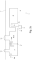
- FIG. 1 shows a schematic view of a cleaning and infiltration system 1 installed beneath a road 7.
- Fig. 1 shows only the structure of the respective treatment and infiltration system 1 without rainwater.
- Stage 22 which precedes storage/infiltration stage 2, is in Fig. 1 a cleaning stage 3.
- the rainwater can be fed to the cleaning stage 3 via an inlet 9a.
- the inlet 9a has a hydrostatic gradient so that the rainwater can be fed to the cleaning stage 3 without the application of force.
- the cleaning stage 3 has maintenance openings 14 which enable above-ground maintenance work on the underground cleaning and infiltration system 1.
- the purification stage 3 becomes flooded so that the rainwater can be fed to the storage/infiltration stage 2 via an inlet 4. Because the purification stage 3 must be flooded so that the rainwater can flow into the storage/infiltration stage 2, the purification stage 3 serves as an intermediate storage facility for the rainwater. In the storage/infiltration stage, the rainwater purified in the purification stage 3 is not only stored, but also seeps into the soil surrounding the purification and infiltration system. The drying out of the purification stage when the rainfall event subsides is prevented by the drainage element. 5.
- the stage 22 preceding the storage/infiltration stage 2 can also be a treatment stage 8, which is preceded by a cleaning stage 3.
- This structure is in Fig. 2 shown schematically.
- the cleaning stage 3 and the treatment stage 8 are connected to one another via an inlet 9b.
- This inlet 9b also has a hydrostatic gradient so that both the cleaning stage 3 and the treatment stage 8 serve as intermediate storage for the rainwater.
- Both the cleaning stage 3 and the treatment stage 8 each have a maintenance opening 14 for maintenance work.
- the drain element 5 is connected to the treatment stage 8 via a pipe 15 leading away and via an inlet 9c to the drain element 5.
- the rainwater can be fed to the storage/infiltration stage 2 via an inlet 4. In the storage/infiltration system, the rainwater seeps into the soil 6.
- Fig. 2b shows a similar structure as Fig. 2a , whereby the cleaning stage 3 is provided with its own drainage element 5 ⁇ , which not only allows the rainwater from the cleaning stage 3 to drain via the inlet 9b into the treatment stage 8, but - of course to a much lesser extent - also allows it to drain into the surrounding soil so that the cleaning stage can dry out.
- Fig. 2c a structure in which, instead of such a drain 5' into the ground, a drain 5" is provided, which creates an additional connection between the cleaning stage 3 and the treatment stage 8. In this way, the cleaning stage 3 can also dry out, since the rainwater from the cleaning stage 3 can now still flow into the treatment stage 8 via this drain 5" if the water level in the cleaning stage is not sufficiently high.
- Fig. 3a shows schematically a cleaning and infiltration system 1 similar to Fig. 1 with overflow cleaning level 3, while Fig. 3b a cleaning and infiltration system 1 similar to Fig. 1 schematically shows cleaning stage 3 when not overloaded.
- the rainwater 13 is fed to the purification stage 3 via an inlet 9a.
- the rainwater usually contains foreign substances 12 in the form of solids, light liquids and dissolved substances. These foreign substances 12 represent contamination that is to be removed in the purification stage.
- the purification stage is divided into a sedimentation section 16, a sorption section 17 and a membrane filter section 18.
- the sorption section 17 comprises coalescence fabric 19, sorption fabric 20 and ion exchange surfaces 21.
- the membrane filter section 18 comprises membrane filters (not shown).
- the container of the storage/infiltration stage 2 is covered with a water-permeable textile 11 so that the rainwater 13 can seep through the water-permeable textile 11 into the soil 6.
- a small proportion of the rainwater 13 seeps through the drainage element 5 at the same time.
- the drainage element 5 has holes 10 through which the rainwater 13 can be discharged to the soil 6.
- the diameter of the holes 10 defines the speed at which the rainwater 13 can be discharged to the soil 6. Since the diameter is selected to be relatively small, the proportion of the rainwater 13 that is discharged into the soil 6 through this leakage is relatively small compared to the proportion that is discharged to the soil 6 via the storage/infiltration stage 2.
- the drainage element is coupled to the cleaning stage 3 via an inlet 9c.
- the drainage element 5 has holes 10 through which the rainwater 13 can be discharged into the soil 6. The remaining rainwater 13 therefore does not seep into the soil 6 via the storage/infiltration stage 2, but rather via the drainage element 5.
- the cleaning stage 3 can therefore dry out practically completely.
Landscapes
- Health & Medical Sciences (AREA)
- Life Sciences & Earth Sciences (AREA)
- Engineering & Computer Science (AREA)
- Hydrology & Water Resources (AREA)
- Public Health (AREA)
- Water Supply & Treatment (AREA)
- Sewage (AREA)
Claims (12)
- Système de purification et d'infiltration (1) pour l'eau pluviale (13), comprenantun étage de stockage/infiltration (2) et un étage (22) en amont de l'étage de stockage/infiltration (2), dans lequell'étage de stockage/infiltration (2) est conçu pour recevoir en son sein l'eau pluviale (13) pour stockage temporaire et pour la distribuer pour infiltration,l'étage (22) agencé en amont de l'étage de stockage/infiltration (2) est couplé à l'étage de stockage/infiltration (2) de telle sorte qu'un débit sortant de l'eau pluviale (13) depuis l'étage agencé en amont de l'étage de stockage/infiltration (2) dans l'étage de stockage/infiltration (2) est possible uniquement lorsque l'étage (22) agencé en amont de l'étage de stockage/infiltration (2) est obstrué,l'étage (22) agencé en amont de l'étage de stockage/infiltration (2) est un étage de purification (3) ou l'étage (22) agencé en amont de l'étage de stockage/infiltration (2) est un étage de traitement (8) qui est agencé en aval d'un étage de purification (3), etl'étage (22) agencé en amont de l'étage de stockage/infiltration (2) a un élément d'évacuation (5), qui permet également alors toujours une évacuation au moins partielle de l'eau pluviale (13) présente dans l'étage (22) agencé en amont de l'étage de stockage/infiltration (2) lorsque l'eau pluviale (13) ne s'écoule plus depuis l'étage (22) agencé en amont de l'étage de stockage/infiltration (2) dans l'étage de stockage/infiltration (2),caractérisé en ce quel'élément d'évacuation (5) est réalisé d'une façon telle que, lorsque l'étage (22) agencé en amont de l'étage de stockage/infiltration (2) déborde, un constituant principal de l'eau pluviale (13) d'au moins 95 % peut s'infiltrer par le biais de l'étage de stockage/infiltration (2), alors qu'au même moment une plus petite partie peut s'infiltrer sous forme de fuites à travers l'élément d'évacuation (5).
- Système de purification et d'infiltration (1) selon la revendication 1, caractérisé en ce que l'élément d'évacuation (5) permet à l'étage (22) agencé en amont de l'étage de stockage/infiltration (2) de s'assécher.
- Système de purification et d'infiltration (1) selon la revendication 1, caractérisé en ce que l'étage de stockage/infiltration (2) et l'élément d'évacuation (5) dans l'état installé sont conçus pour distribuer l'eau pluviale (13) pour infiltration dans une région de terre entourant (6) l'étage de stockage/infiltration (2) ou l'élément d'évacuation (5) dans un réseau d'égouts ou dans une installation de ruissellement.
- Système de purification et d'infiltration (1) selon l'une quelconque des revendications 1 à 3, caractérisé en ce que l'étage de purification (3) a un débit entrant (9a), par le biais duquel l'eau pluviale (13) peut être introduite dans l'étage de purification (3), dans lequel le débit entrant (9a) a un gradient hydrostatique.
- Système de purification et d'infiltration (1) selon l'une quelconque des revendications 1 à 4, caractérisé en ce que l'étage de purification (3) et/ou l'étage de traitement (8) sont conçus pour recevoir en leur sein l'eau pluviale (13) pour stockage temporaire.
- Système de purification et d'infiltration (1) selon l'une quelconque des revendications 1 à 5, caractérisé en ce que l'étage de purification (3) est conçu pour purifier l'eau pluviale (13) des solides, des liquides légers et/ou des substances dissoutes (12).
- Système de purification et d'infiltration (1) selon l'une quelconque des revendications 1 à 6, caractérisé en ce que l'étage de purification (3) comprend une partie de sédimentation (16), une partie de sorption (17) et/ou une partie de filtre à membrane (18).
- Système de purification et d'infiltration (1) selon l'une quelconque des revendications précédentes, caractérisé en ce que l'eau pluviale (13) peut être introduite par le biais d'un débit entrant (4) de l'étage de stockage/infiltration (2), dans lequel le débit entrant (4) est placé d'une façon telle que l'eau pluviale (13) peut atteindre le débit entrant (4) uniquement à un niveau de remplissage prédéterminé de l'étage (22) agencé en amont de l'étage de stockage/infiltration (2).
- Système de purification et d'infiltration (1) selon l'une quelconque des revendications précédentes, caractérisé en ce que l'élément d'évacuation (5) est positionné d'une façon telle qu'un débit entrant (9c) de l'élément d'évacuation (5) a un gradient hydrostatique.
- Système de purification et d'infiltration (1) selon l'une quelconque des revendications précédentes, caractérisé en ce que l'élément d'évacuation (5) a des orifices (10) et/ou est gainé d'un textile perméable à l'eau.
- Système de purification et d'infiltration (1) selon l'une quelconque des revendications précédentes, caractérisé en ce que l'élément d'évacuation (5) est relié à l'étage (22) agencé en amont de l'étage de stockage/infiltration (2) directement ou par le biais d'un pipeline (15) éloignant de l'étage (22) agencé en amont de l'étage de stockage/infiltration (2).
- Système de purification et d'infiltration (1) selon l'une quelconque des revendications précédentes, caractérisé en ce que l'élément d'évacuation (5) peut être commandé d'une façon telle que sa fonction d'évacuation peut être allumée ou éteinte ou peut être régulée.
Applications Claiming Priority (1)
| Application Number | Priority Date | Filing Date | Title |
|---|---|---|---|
| DE102020113718.4A DE102020113718A1 (de) | 2020-05-20 | 2020-05-20 | Reinigungs- und Versickerungsanlage |
Publications (3)
| Publication Number | Publication Date |
|---|---|
| EP3913157A1 EP3913157A1 (fr) | 2021-11-24 |
| EP3913157C0 EP3913157C0 (fr) | 2024-11-27 |
| EP3913157B1 true EP3913157B1 (fr) | 2024-11-27 |
Family
ID=75887930
Family Applications (1)
| Application Number | Title | Priority Date | Filing Date |
|---|---|---|---|
| EP21173060.1A Active EP3913157B1 (fr) | 2020-05-20 | 2021-05-10 | Installation de nettoyage et de percolation |
Country Status (2)
| Country | Link |
|---|---|
| EP (1) | EP3913157B1 (fr) |
| DE (1) | DE102020113718A1 (fr) |
Family Cites Families (7)
| Publication number | Priority date | Publication date | Assignee | Title |
|---|---|---|---|---|
| DE4226660A1 (de) | 1992-08-12 | 1994-02-17 | Oase Pumpen | Filter für Teichwasser |
| US7137755B2 (en) | 2001-07-24 | 2006-11-21 | Norman Jeffrey J | Underground water retention apparatus |
| AU2008252265B2 (en) | 2007-05-17 | 2010-09-30 | Totetu Mfg. Co. Ltd. | Dust-removal managing pit |
| KR100966038B1 (ko) * | 2009-09-04 | 2010-06-25 | 주식회사 한국종합환경 | 우수 침투 시스템 |
| KR101288606B1 (ko) * | 2011-06-21 | 2013-07-22 | 주식회사 유비이엔씨 | 침투도랑 |
| KR101222885B1 (ko) * | 2012-07-06 | 2013-01-17 | (주)청운환경기술 | 초기 우수를 배제한 우수 포집장치 |
| DE202012010941U1 (de) | 2012-11-15 | 2013-01-09 | Martin Heitker | Vorrichtung zum Behandeln von Regenwasser |
-
2020
- 2020-05-20 DE DE102020113718.4A patent/DE102020113718A1/de active Pending
-
2021
- 2021-05-10 EP EP21173060.1A patent/EP3913157B1/fr active Active
Also Published As
| Publication number | Publication date |
|---|---|
| EP3913157A1 (fr) | 2021-11-24 |
| DE102020113718A1 (de) | 2021-11-25 |
| EP3913157C0 (fr) | 2024-11-27 |
Similar Documents
| Publication | Publication Date | Title |
|---|---|---|
| DE69717621T2 (de) | Vorrichtung und methode zur behandlung von abfliessendem regenwasser | |
| EP2769029B1 (fr) | Dispositif de drainage | |
| EP2085527B1 (fr) | Installation d'exploitation d'eau de pluie | |
| DE19539537A1 (de) | Wasseraufbereitungsanlage | |
| DE102010044971A1 (de) | Filtervorrichtung für einen Straßenablauf | |
| DE202012011112U1 (de) | Vorrichtung zur Reinigung von verschmutztem Niederschlagswasser oder dergleichen im Straßenablauf (Gully) | |
| EP2410095B1 (fr) | Installation de traitement pour eau de pluie | |
| EP2659944B1 (fr) | Agencement de filtration et procédé d'intégration de l'agencement de filtration | |
| EP3460133A1 (fr) | Système d'infiltration | |
| EP2428259B1 (fr) | Dispositif de traitement des eaux usées et installation de traitement des eaux usées dotée d'un tel dispositif de traitement des eaux usées | |
| DE19533935C2 (de) | Vorrichtung für die Reinigung von Abwasser | |
| EP3913157B1 (fr) | Installation de nettoyage et de percolation | |
| EP3730706B1 (fr) | Système de stockage/percolation | |
| AT410453B (de) | Entwässerungssystem | |
| EP1927388A1 (fr) | Système de filtre de réservoir des eaux pluviales | |
| DE3918803C2 (de) | Einrichtung zum Reinigen von Oberflächenwasser | |
| DE102017108820A1 (de) | Filteranlage | |
| DE102010013473B4 (de) | Abwasserreinigungsvorrichtung und -verfahren | |
| EP1522525B1 (fr) | Dispositif et puits pour le traitement décentralisé de l'eau et procédé correspondant | |
| DE202005016136U1 (de) | Schachtanordnung | |
| AT527034B1 (de) | Auslaufbehälter, System und Verfahren zur Oberflächenentwässerung | |
| EP0105225A2 (fr) | Procédé de nettoyage d'un élément de filtration pour les substances liquides et du dispositif de séparation renfermant cet élément | |
| DE102019132076A1 (de) | Abscheidevorrichtung | |
| DE102023105975A1 (de) | Wassereinlaufeinrichtung für eine Filtereinheit, Filtereinheit und Filtersystem | |
| DE102005044166A1 (de) | Verfahren und Vorrichtung zum Reinigen von Regenabwasser |
Legal Events
| Date | Code | Title | Description |
|---|---|---|---|
| PUAI | Public reference made under article 153(3) epc to a published international application that has entered the european phase |
Free format text: ORIGINAL CODE: 0009012 |
|
| STAA | Information on the status of an ep patent application or granted ep patent |
Free format text: STATUS: THE APPLICATION HAS BEEN PUBLISHED |
|
| AK | Designated contracting states |
Kind code of ref document: A1 Designated state(s): AL AT BE BG CH CY CZ DE DK EE ES FI FR GB GR HR HU IE IS IT LI LT LU LV MC MK MT NL NO PL PT RO RS SE SI SK SM TR |
|
| B565 | Issuance of search results under rule 164(2) epc |
Effective date: 20211006 |
|
| STAA | Information on the status of an ep patent application or granted ep patent |
Free format text: STATUS: REQUEST FOR EXAMINATION WAS MADE |
|
| 17P | Request for examination filed |
Effective date: 20220301 |
|
| RBV | Designated contracting states (corrected) |
Designated state(s): AL AT BE BG CH CY CZ DE DK EE ES FI FR GB GR HR HU IE IS IT LI LT LU LV MC MK MT NL NO PL PT RO RS SE SI SK SM TR |
|
| STAA | Information on the status of an ep patent application or granted ep patent |
Free format text: STATUS: EXAMINATION IS IN PROGRESS |
|
| 17Q | First examination report despatched |
Effective date: 20230323 |
|
| GRAP | Despatch of communication of intention to grant a patent |
Free format text: ORIGINAL CODE: EPIDOSNIGR1 |
|
| STAA | Information on the status of an ep patent application or granted ep patent |
Free format text: STATUS: GRANT OF PATENT IS INTENDED |
|
| INTG | Intention to grant announced |
Effective date: 20240812 |
|
| GRAS | Grant fee paid |
Free format text: ORIGINAL CODE: EPIDOSNIGR3 |
|
| GRAA | (expected) grant |
Free format text: ORIGINAL CODE: 0009210 |
|
| STAA | Information on the status of an ep patent application or granted ep patent |
Free format text: STATUS: THE PATENT HAS BEEN GRANTED |
|
| AK | Designated contracting states |
Kind code of ref document: B1 Designated state(s): AL AT BE BG CH CY CZ DE DK EE ES FI FR GB GR HR HU IE IS IT LI LT LU LV MC MK MT NL NO PL PT RO RS SE SI SK SM TR |
|
| REG | Reference to a national code |
Ref country code: GB Ref legal event code: FG4D Free format text: NOT ENGLISH |
|
| REG | Reference to a national code |
Ref country code: CH Ref legal event code: EP |
|
| REG | Reference to a national code |
Ref country code: IE Ref legal event code: FG4D Free format text: LANGUAGE OF EP DOCUMENT: GERMAN |
|
| REG | Reference to a national code |
Ref country code: DE Ref legal event code: R096 Ref document number: 502021005925 Country of ref document: DE |
|
| U01 | Request for unitary effect filed |
Effective date: 20241210 |
|
| U07 | Unitary effect registered |
Designated state(s): AT BE BG DE DK EE FI FR IT LT LU LV MT NL PT RO SE SI Effective date: 20241219 |
|
| PG25 | Lapsed in a contracting state [announced via postgrant information from national office to epo] |
Ref country code: IS Free format text: LAPSE BECAUSE OF FAILURE TO SUBMIT A TRANSLATION OF THE DESCRIPTION OR TO PAY THE FEE WITHIN THE PRESCRIBED TIME-LIMIT Effective date: 20250327 Ref country code: HR Free format text: LAPSE BECAUSE OF FAILURE TO SUBMIT A TRANSLATION OF THE DESCRIPTION OR TO PAY THE FEE WITHIN THE PRESCRIBED TIME-LIMIT Effective date: 20241127 |
|
| PG25 | Lapsed in a contracting state [announced via postgrant information from national office to epo] |
Ref country code: ES Free format text: LAPSE BECAUSE OF FAILURE TO SUBMIT A TRANSLATION OF THE DESCRIPTION OR TO PAY THE FEE WITHIN THE PRESCRIBED TIME-LIMIT Effective date: 20241127 |
|
| PG25 | Lapsed in a contracting state [announced via postgrant information from national office to epo] |
Ref country code: NO Free format text: LAPSE BECAUSE OF FAILURE TO SUBMIT A TRANSLATION OF THE DESCRIPTION OR TO PAY THE FEE WITHIN THE PRESCRIBED TIME-LIMIT Effective date: 20250227 |
|
| PG25 | Lapsed in a contracting state [announced via postgrant information from national office to epo] |
Ref country code: GR Free format text: LAPSE BECAUSE OF FAILURE TO SUBMIT A TRANSLATION OF THE DESCRIPTION OR TO PAY THE FEE WITHIN THE PRESCRIBED TIME-LIMIT Effective date: 20250228 |
|
| PG25 | Lapsed in a contracting state [announced via postgrant information from national office to epo] |
Ref country code: PL Free format text: LAPSE BECAUSE OF FAILURE TO SUBMIT A TRANSLATION OF THE DESCRIPTION OR TO PAY THE FEE WITHIN THE PRESCRIBED TIME-LIMIT Effective date: 20241127 |
|
| PG25 | Lapsed in a contracting state [announced via postgrant information from national office to epo] |
Ref country code: RS Free format text: LAPSE BECAUSE OF FAILURE TO SUBMIT A TRANSLATION OF THE DESCRIPTION OR TO PAY THE FEE WITHIN THE PRESCRIBED TIME-LIMIT Effective date: 20250227 |
|
| U20 | Renewal fee for the european patent with unitary effect paid |
Year of fee payment: 5 Effective date: 20250512 |
|
| PG25 | Lapsed in a contracting state [announced via postgrant information from national office to epo] |
Ref country code: SM Free format text: LAPSE BECAUSE OF FAILURE TO SUBMIT A TRANSLATION OF THE DESCRIPTION OR TO PAY THE FEE WITHIN THE PRESCRIBED TIME-LIMIT Effective date: 20241127 |
|
| PG25 | Lapsed in a contracting state [announced via postgrant information from national office to epo] |
Ref country code: SK Free format text: LAPSE BECAUSE OF FAILURE TO SUBMIT A TRANSLATION OF THE DESCRIPTION OR TO PAY THE FEE WITHIN THE PRESCRIBED TIME-LIMIT Effective date: 20241127 |
|
| PG25 | Lapsed in a contracting state [announced via postgrant information from national office to epo] |
Ref country code: CZ Free format text: LAPSE BECAUSE OF FAILURE TO SUBMIT A TRANSLATION OF THE DESCRIPTION OR TO PAY THE FEE WITHIN THE PRESCRIBED TIME-LIMIT Effective date: 20241127 |
|
| PLBE | No opposition filed within time limit |
Free format text: ORIGINAL CODE: 0009261 |
|
| STAA | Information on the status of an ep patent application or granted ep patent |
Free format text: STATUS: NO OPPOSITION FILED WITHIN TIME LIMIT |
|
| REG | Reference to a national code |
Ref country code: CH Ref legal event code: L10 Free format text: ST27 STATUS EVENT CODE: U-0-0-L10-L00 (AS PROVIDED BY THE NATIONAL OFFICE) Effective date: 20251008 |
|
| 26N | No opposition filed |
Effective date: 20250828 |
|
| REG | Reference to a national code |
Ref country code: CH Ref legal event code: H13 Free format text: ST27 STATUS EVENT CODE: U-0-0-H10-H13 (AS PROVIDED BY THE NATIONAL OFFICE) Effective date: 20251223 |
|
| PG25 | Lapsed in a contracting state [announced via postgrant information from national office to epo] |
Ref country code: CH Free format text: LAPSE BECAUSE OF NON-PAYMENT OF DUE FEES Effective date: 20250531 |
|
| GBPC | Gb: european patent ceased through non-payment of renewal fee |
Effective date: 20250510 |
|
| PG25 | Lapsed in a contracting state [announced via postgrant information from national office to epo] |
Ref country code: MC Free format text: LAPSE BECAUSE OF FAILURE TO SUBMIT A TRANSLATION OF THE DESCRIPTION OR TO PAY THE FEE WITHIN THE PRESCRIBED TIME-LIMIT Effective date: 20241127 |
|
| PG25 | Lapsed in a contracting state [announced via postgrant information from national office to epo] |
Ref country code: GB Free format text: LAPSE BECAUSE OF NON-PAYMENT OF DUE FEES Effective date: 20250510 |
|
| PG25 | Lapsed in a contracting state [announced via postgrant information from national office to epo] |
Ref country code: IE Free format text: LAPSE BECAUSE OF NON-PAYMENT OF DUE FEES Effective date: 20250510 |