EP1522587A2 - Verfahren zur Einbringung von Nukleinsäuren und anderen biologisch aktiven Molekülen in den Kern höherer eukaryontischer Zellen mit Hilfe elektrischen Stroms - Google Patents
Verfahren zur Einbringung von Nukleinsäuren und anderen biologisch aktiven Molekülen in den Kern höherer eukaryontischer Zellen mit Hilfe elektrischen Stroms Download PDFInfo
- Publication number
- EP1522587A2 EP1522587A2 EP04024956A EP04024956A EP1522587A2 EP 1522587 A2 EP1522587 A2 EP 1522587A2 EP 04024956 A EP04024956 A EP 04024956A EP 04024956 A EP04024956 A EP 04024956A EP 1522587 A2 EP1522587 A2 EP 1522587A2
- Authority
- EP
- European Patent Office
- Prior art keywords
- pulse
- charge
- cells
- amount
- voltage
- Prior art date
- Legal status (The legal status is an assumption and is not a legal conclusion. Google has not performed a legal analysis and makes no representation as to the accuracy of the status listed.)
- Granted
Links
Images




Classifications
-
- C—CHEMISTRY; METALLURGY
- C12—BIOCHEMISTRY; BEER; SPIRITS; WINE; VINEGAR; MICROBIOLOGY; ENZYMOLOGY; MUTATION OR GENETIC ENGINEERING
- C12N—MICROORGANISMS OR ENZYMES; COMPOSITIONS THEREOF; PROPAGATING, PRESERVING, OR MAINTAINING MICROORGANISMS; MUTATION OR GENETIC ENGINEERING; CULTURE MEDIA
- C12N13/00—Treatment of microorganisms or enzymes with electrical or wave energy, e.g. magnetism, sonic waves
-
- A—HUMAN NECESSITIES
- A61—MEDICAL OR VETERINARY SCIENCE; HYGIENE
- A61N—ELECTROTHERAPY; MAGNETOTHERAPY; RADIATION THERAPY; ULTRASOUND THERAPY
- A61N1/00—Electrotherapy; Circuits therefor
- A61N1/18—Applying electric currents by contact electrodes
- A61N1/32—Applying electric currents by contact electrodes alternating or intermittent currents
- A61N1/327—Applying electric currents by contact electrodes alternating or intermittent currents for enhancing the absorption properties of tissue, e.g. by electroporation
-
- A—HUMAN NECESSITIES
- A61—MEDICAL OR VETERINARY SCIENCE; HYGIENE
- A61N—ELECTROTHERAPY; MAGNETOTHERAPY; RADIATION THERAPY; ULTRASOUND THERAPY
- A61N1/00—Electrotherapy; Circuits therefor
- A61N1/02—Details
- A61N1/04—Electrodes
- A61N1/0404—Electrodes for external use
- A61N1/0408—Use-related aspects
- A61N1/0412—Specially adapted for transcutaneous electroporation, e.g. including drug reservoirs
-
- C—CHEMISTRY; METALLURGY
- C12—BIOCHEMISTRY; BEER; SPIRITS; WINE; VINEGAR; MICROBIOLOGY; ENZYMOLOGY; MUTATION OR GENETIC ENGINEERING
- C12N—MICROORGANISMS OR ENZYMES; COMPOSITIONS THEREOF; PROPAGATING, PRESERVING, OR MAINTAINING MICROORGANISMS; MUTATION OR GENETIC ENGINEERING; CULTURE MEDIA
- C12N15/00—Mutation or genetic engineering; DNA or RNA concerning genetic engineering, vectors, e.g. plasmids, or their isolation, preparation or purification; Use of hosts therefor
- C12N15/09—Recombinant DNA-technology
- C12N15/87—Introduction of foreign genetic material using processes not otherwise provided for, e.g. co-transformation
-
- H—ELECTRICITY
- H03—ELECTRONIC CIRCUITRY
- H03K—PULSE TECHNIQUE
- H03K3/00—Circuits for generating electric pulses; Monostable, bistable or multistable circuits
- H03K3/02—Generators characterised by the type of circuit or by the means used for producing pulses
- H03K3/53—Generators characterised by the type of circuit or by the means used for producing pulses by the use of an energy-accumulating element discharged through the load by a switching device controlled by an external signal and not incorporating positive feedback
- H03K3/57—Generators characterised by the type of circuit or by the means used for producing pulses by the use of an energy-accumulating element discharged through the load by a switching device controlled by an external signal and not incorporating positive feedback the switching device being a semiconductor device
Definitions
- the invention relates to a method for introducing nucleic acids, Peptides, proteins and / or other biologically active molecules in the Cell nucleus of eukaryotic cells by means of electrical current, wherein at least a voltage pulse is transmitted to the cells.
- eukaryotic DNA Since the site of action of eukaryotic DNA is the nucleus, must be from the outside added DNA into the core to be read. Conventional transfection methods only cause a transport of DNA through the cell membrane into the cytoplasm. Just because higher in cell division Eukaryotes the nuclear envelope is temporarily dissolved, the DNA can be passive enter the nucleus so that encoded proteins are expressed by it can. Only very small DNA molecules (oligonucleotides) can be released by the Pores of the nuclear envelope diffuse. For effective transfection dormant or weak division-active cells, conditions must be created, which cause even larger DNA molecules in sufficient quantity pass through the nuclear membrane into the nucleus. The one described here Procedure allows this in higher eukaryotic cells.
- U.S. Patent 5,869,326 (Genetronics, Inc., San Diego, USA, 1996) describes a specific device construction, by means of two separate power sources two, three or more pulses are generated can. It is not claimed or shown that these pulses an effect beyond the transport of DNA into the cytoplasm to have.
- the invention has for its object to provide a method available represent the effective transport of DNA and / or biologically active Molecules in the nucleus with low cell mortality allows.
- the invention is provided to solve the problem that by the Voltage pulse delivered amount of charge in at least one selectable Time interval is measured, wherein a comparison of a preset target charge amount is performed with the delivered actual amount of charge, and that upon reaching or exceeding the target amount of charge the Voltage pulse is canceled.
- first a first pulse with the voltage U 1 is transmitted to the cells and that subsequently without interruption at least a second pulse with the voltage U 2 is also transmitted to the cells.
- a comparison of the preset target charge amount is performed with the output actual charge amount alternatively in a time interval and locked upon reaching or exceeding the target charge amount of power semiconductors.
- the time interval which can be selected for the determination can be specified individually in order to determine, for example, the quantity of charge delivered during the first or each subsequent subsequent pulse.
- the determination of the amount of charge delivered can be made by determining the difference between the original charge of at least one of the storage devices and the remaining charge.
- each memory device is assigned at least one high-voltage power supply, a control device and a power semiconductor for transmitting the charge quantity to the cuvette with the cell suspension.
- the first power semiconductor transmits a pulse of 2-10 kV / cm with a duration of 10 - 100 microseconds and a current density of at least 2 A cm -2 and the second power semiconductor without interruption a pulse with a Current density of 2 - 14 A cm -2 transmits a maximum duration of 100 ms.
- the time interval for determining the amount of charge delivered can thus be determined with the delivery of a first and / or preferably a second or each further pulse.
- the duty cycle (T 2 ) of the second pulse by a comparison of the desired charge amount with the delivered up to the measurement instant actual charge amount can be determined and ends with reaching the desired charge amount and wherein the Determining the actual amount of charge a measurement cycle of 1 msec is provided, wherein during the time (T 2 ), the capacitor voltage drops exponentially and upon reaching the set amount of charge (Q 2 ) of the power semiconductor is blocked.
- the duration of the pulse is nachregelbar to the delivered To keep charge amount constant.
- the Possibility that after at least a predetermined time interval after Triggering a first and / or second pulse of the flowing current measured and an error message when exceeding or falling below a setpoint is done to give the user of the device a warning.
- the other necessary pulse parameters become manually preselected or defined by entering a code if necessary. It Therefore, there is also the possibility of retrievable data via a card reader use.
- the card reader can be used at the same time, the temporal course of the voltage applied to the cuvette or by the Cuvette of flowing stream for documentation purposes for one or more Store pulse delivery operations on a commercially available memory card. This memory card is preferably used at the same time for storing the to be set pulse parameters.
- circuitry control of the pulse output is thus in reliable and advantageous way of transferring the intended Charge quantity monitored for at least one pulse and a controlled and sample-dependent transmission of a preset amount of charge and controlled surveillance to prevent damage to the allows the sample located cells.
- overcurrent shutdown for the first and each further impulse is provided.
- the overcurrent shutdown thus allows at any time the interruption of the high voltage pulse in the event that preset limits are exceeded.
- the described high voltage pulse of 2 - 10 kV / cm is suitable for To create conditions that serve to make DNA independent of the Cell division can enter the nucleus.
- This pulse is limited to 10 to a maximum of 200 ⁇ s, preferably 10-50 ⁇ s. This is sufficient to achieve cell division-independent transfection.
- Umbilical vein for example, turned out to be such a short individual High voltage pulse as optimal.
- Another without interruption following pulse of lower field strength and lower current intensity or Current density, but longer duration has an influence on the efficiency of the Transfection. Due to the significantly lower current density, this pulse can slow cell damage significantly longer.
- the amount of charge delivered is controlled.
- the resistance of the cuvette and of the cell suspension contained therein must initially be predetermined. It has been shown that electrochemical processes change the resistance of the cuvettes used with aluminum electrodes during the pulse. This change is taken into account by a pulse-specific predetermined correction value.
- U 2 R x I 2 x K 2
- the ohmic cuvette resistance R can be measured in an embodiment of the invention immediately before the start of the Pulsab bo by applying a test voltage and taken into account in the calculation of the voltage U 2 . Since the resistance measured before the pulse outputs - presumably due to electrochemical processes - subject to greater fluctuations than the resistance during the pulse outputs, it proves advantageous to predetermine the resistance R for calculating the capacitor voltage U 2 as a parameter. In a preferred embodiment of the invention, however, the resistance of the cuvette is measured prior to the start of the pulse outputs to determine if it is within a predetermined resistance window. If the measured resistance is outside this window, there is a fault and the pulse output is not released.
- Adjust transfection intensity and cell vitality For each cell type optimal conditions for transfection rate, Adjust transfection intensity and cell vitality.
- the method is advantageously dormant for transfection or can be used for division-active eukaryotic cells.
- the procedure for the transfection of primary cells such as cells of human blood, pluripotent progenitor cells of human blood, primary human Fibroblasts, endothelial cells, muscle cells or melanocytes are suitable and may be used for analytical or diagnostic purposes or for the preparation of a Medicinal product for ex vivo gene therapy.
- the inventive method is also suitable, for example also for the electrofusion, i.
- Process for the fusion of cells, cell derivatives, Subcellular particles and / or vesicles by means of electrical current in which for example, the cells, cell derivatives, subcellular particles and / or vesicles initially suspended in an appropriate density in an aqueous solution
- the suspension is then transferred to a cuvette, and finally, an electrical voltage is applied to the electrodes of the cuvette and a current flow through the suspension is generated.
- the method described here uses very high field strengths of 2 to 10 kV / cm, which cause DNA and / or other biologically active molecules regardless of cell division can get into the nucleus. These Field strengths are far beyond the usual for electroporation and far beyond the field strengths necessary for efficient opening of pores in the cell membrane sufficient (average 1 kV / cm according to Lurquin, 1997, Mol. Biotechnol. 7, 5).
- the invention therefore relates to a method for implementing a method for introducing nucleic acids, peptides, proteins and / or other biologically active molecules into the nucleus of higher eukaryotic cells by means of electrical current, wherein the introduction into the nucleus by a pulse with the 2 - 10 times the value of the field strength which is sufficient for the pore opening in the cell membrane and a duration of at least 10 ⁇ s and a current density of at least 2 A cm -2 is achieved.
- nucleic acids, peptides, proteins and / or others Biologically active molecules in the cell nucleus can thereby by an impulse of 2-10 kV / cm, preferably 3-8 kV / cm, the pulse maximum 200 ⁇ s long.
- the method is designed so that on the first pulse without interruption, a current flow with a current density of 2 A cm -2 to a maximum of 14 A cm -2 , preferably to 5 A cm -2 , from 1 ms to max. 100 ms, preferably up to 50 ms, length can follow.
- the procedure allows transfection independent of cell division, In addition to division-active cells, they can also be dormant or weak divisionally active primary cells are transfected.
- inventions of the invention are primary peripheral human blood cells as well as pluripotent progenitor cells of the human Blood transfected.
- the higher ones comprise eukaryotic cells are primary human fibroblasts, endothelial cells and Melanocytes.
- the transfected by the method according to the invention eukaryotic Cells can be used for diagnostic and analytical purposes and for manufacture of a drug for ex vivo gene therapy.
- the inventive method allows a cell division independent Transfection and thus a significant acceleration of Transfection experiments.
- transfection experiments with Expression vectors is an analysis depending on the promoter and expressed Protein only a few hours after transfection possible.
- biologically active molecules means peptides, proteins, Polysaccharides, lipids or combinations or derivatives of these molecules, as long as they develop a biological activity in the cell.
- Electroporation buffer with high ionic strength and high buffering capacity.
- the following protocol can be used: 1 ⁇ 10 5 - 1 ⁇ 10 7 cells and up to 10 ⁇ g of DNA are incubated in 100 ⁇ l electroporation buffer in a cuvette with 2 mm electrode gap for 10 min. incubated at room temperature and then transfected according to the conditions of the invention. Immediately thereafter, the cells are rinsed out of the cuvette with 400 ⁇ l of cell culture medium and incubated for 10 min. incubated at 37 ° C. Thereafter, the cells are plated in 37 ° C warm cell culture medium.
- Suitable cuvettes are those with an electrode spacing of 2 mm or 1 mm, z.
- Freshly prepared unstimulated (dividing-inactive) peripheral human blood mononuclear cells (PBMC) were transfected with a vector coding for the mouse MHC class I protein H-2K k heavy chain.
- 5 ⁇ 10 6 cells were placed in a cuvette with 2 mm electrode gap with 5 ⁇ g of vector DNA in a buffer with high buffer capacity (48 mM ⁇ pH -1 ) and high ionic strength (280 mM) at room temperature and by a pulse of 1000 V. and 100 ⁇ s duration, followed by a current flow transfected at a current density of 5 A cm -2 and 40 ms duration.
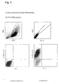
- the cells were rinsed from the cuvette with 400 ⁇ l of culture medium, incubated at 37 ° C for 10 minutes, and then transferred to a culture dish with preheated medium. After incubation for 24 h, the cells were incubated sequentially with digoxygenin-coupled anti-H-2K k antibody and Cy5-coupled anti-digoxygenin antibody, as well as with a PerCP-coupled anti-CD8 antibody to identify human cytotoxic T cells analyzed with a flow cytometer (FACScalibur, Becton Dickinson). By staining with propidium iodide, the number of dead cells was determined. As shown in Figure 1, 74.3% of the living cells express the H-2K k antigen, which corresponds to a very high transfection efficiency.
- CD34-positive cells were pre-enriched by magnetic cell sorting. Subsequently, each 1 ⁇ 10 4 CD34-positive cells were mixed with 1 ⁇ 10 6 PBMCs, with 5 ⁇ g H-2K k expression vector DNA in a buffer with high buffer capacity (54 mM ⁇ pH -1 ) and high ionic strength (260 mM ) at room temperature in a cuvette with 2 mm electrode spacing and transfected by a pulse of 1000 V and 100 .mu.s duration, followed by a current flow with a current density of 4 A cm -2 and 20 ms duration.
- high buffer capacity 54 mM ⁇ pH -1
- high ionic strength 260 mM
- the cells were rinsed from the cuvette with 400 ⁇ l of culture medium, incubated at 37 ° C for 10 minutes, and then transferred to a culture dish with preheated medium. After 16 h of incubation, the cells were sequentially incubated with phycoerythrin-coupled anti-H-2K k antibody, as well as with an APC-coupled anti-CD34 antibody for the identification of human hematopoietic stem cells and with a flow cytometer (FACScalibur, Becton Dickinson) analyzed. By staining with propidium iodide, the number of dead cells was determined. As shown in Figure 2, 66.7% of the cells express the H-2K k antigen, which also corresponds to high transfection efficiency.
- Human neonatal dermal fibroblasts (5 x 10 5 cells) were cultured with 5 ⁇ g H-2K k expression vector DNA in a buffer with high buffer capacity (67 mM x pH -1 ) and high ionic strength (380 mM) at room temperature in a cuvette 2 mm electrode spacing and transfected by a pulse of 1000 V and 100 ⁇ s duration, followed by a current flow with a current density of 6A cm -2 and 33 ms duration.
- the cells were rinsed from the cuvette with 400 ⁇ l of culture medium, incubated at 37 ° C for 10 minutes, and then transferred to a culture dish with preheated medium.
- the cells were incubated with a Cy5-coupled anti-H-2K k antibody and analyzed with a flow cytometer (FACScalibur, Becton Dickinson). By staining with propidium iodide, the number of dead cells was determined. As shown in Figure 3, 93% of the cells express the H-2K k antigen, which corresponds to a very high transfection efficiency.
- Human neonatal melanocytes (2.5 x 10 5 cells) were cultured with 5 ⁇ g H-2K k expression vector DNA in a buffer with high buffer capacity (54 mM x pH -1 ) and high ionic strength (260 mM) at room temperature in a cuvette with 2 mm electrode spacing and transfected by a pulse of 1000 V and 100 ⁇ s duration, followed by a current flow with a current density of 6 A cm -2 and 33 ms duration.
- the cells were rinsed from the cuvette with 400 ⁇ l of culture medium, incubated at 37 ° C for 10 minutes, and then transferred to a culture dish with preheated medium.
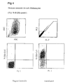
- the cells were analyzed with a Cy5-coupled anti-H-2K k antibody and with a flow cytometer (FACScalibur, Becton Dickinson). Staining with propidium iodide determined the number of dead cells. As shown in Figure 4, 75.1% of the cells express the H-2K k antigen, which corresponds to a very high transfection efficiency.
- Human umbilical cord endothelial cells (1 x 10 6 cells) were cultured with 5 ⁇ g of H-2K k expression vector DNA in a buffer of high buffer capacity (67 mM x pH -1 ) and high ionic strength (378 mM) at room temperature in a cuvette given with 2 mm electrode spacing and transfected by a pulse of 1000 V and 100 ⁇ s duration. Immediately thereafter, the cells were rinsed from the cuvette with 400 ⁇ l of culture medium, incubated at 37 ° C for 10 minutes, and then transferred to a culture dish with preheated medium.
- high buffer capacity 67 mM x pH -1
- high ionic strength 378 mM
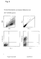
- the cells were incubated with a Cy5-coupled anti-H-2K k antibody and analyzed with a flow cytometer (FACScalibur, Becton Dickinson). By staining with propidium iodide, the number of dead cells was determined. As shown in Figure 5, 49.7% of the living cells express the H-2K k antigen, which corresponds to a high transfection efficiency.
- K562 cells (1 x 10 6 cells) were cultured with 5 ⁇ g H-2K k expression vector DNA in a buffer with high buffer capacity (24 mM x pH -1 ) and high ionic strength (254 mM) at room temperature in a cuvette containing 2 given electrode gap and transfected by a pulse of 1000V and 100 ⁇ s duration, followed by a current flow with a current density of 8 A cm -2 and 10 ms duration. Immediately thereafter, the cells were rinsed from the cuvette with 400 ⁇ l of culture medium, incubated at 37 ° C for 10 minutes, and then transferred to a culture dish with preheated medium.
- the cells were incubated with a Cy5-coupled anti-H-2K k antibody and analyzed with a flow cytometer (FACScalibur, Becton Dickinson). By staining with propidium iodide, the number of dead cells was determined. As shown in Figure 6, 69.5% of the cells express the H-2K k antigen, which also corresponds to high transfection efficiency.
- FIG. 7 shows the determined transfection efficiency as a function of the integral of current over the pulse time (charge quantity Q). It turns out that transfection efficiency can be increased with increasing current (open circles).
- FIG. 8 shows the determined transfection efficiency as a function of the integral of current over the pulse time (charge quantity Q). As with the use of CHO cells, it can be seen that transfection efficiency can be increased with increasing current (open circles).
- FIG. 9 shows the determined transfection efficiency as a function of the integral of current over the pulse time (charge quantity Q).
- transfection efficiency can be increased with increasing current (open circles).
- Increasing the pulse time while keeping the current constant does not result in any significant increase in efficiency (closed circuits).
- the fluorescence intensity (brightness) of the transfected cells increases with an increase in the amount of charge Q, achieving saturation at high Q. There are no major differences between the Q increase being achieved by increasing the current (open circles) or extending the pulses (closed circles).
- Figure 1 shows the flow cytometric analysis of PBMC transfected with the H-2K k expression vector.
- the cells were sequentially incubated with digoxygenin-coupled anti-H-2K k antibody and Cy5-coupled anti-digoxygenin antibody, as well as with a PerCP-coupled anti-CD8 antibody for the identification of human cytotoxic T cells and with a flow-through Cytometer (FACScalibur, Becton Dickinson) analyzed.
- FL-2, FL-3 fluorescence channel 2, 3
- SSC sideward scatter
- FSC forward scatter
- PerCP peridinin chlorophyll protein
- CD cluster of differentiation
- Figure 2 shows the flow cytometric analysis of PBMC-enriched CD34-positive stem cells transfected with the H-2K k expression vector.
- the cells were sequentially incubated with phycoerythrin-coupled anti-H-2K k antibody and with an APC-coupled anti-CD34 antibody for identification of human CD34-positive hematopoietic stem cells and analyzed with a flow cytometer (FACScalibur, Becton Dickinson).
- FL-1, FL-3 fluorescence channel 1, 3
- SSC sideward scatter
- FSC forward scatter
- PE phycoerythrin
- APC allophycocyanin
- CD cluster of differentiation
- Figure 3 shows the flow cytometric analysis of human neonatal dermal fibroblasts (NHDF-Neo) transfected with the H-2K k expression vector.
- the cells were incubated coupled k Cy5 with an anti-H-2K and analyzed with a flow cytometer (FACScalibur, Becton Dickinson).
- Figure 4 shows the flow cytometric analysis of human neonatal melanocytes (NHEM-Neo) transfected with the H-2K k expression vector.
- the cells were incubated coupled k Cy5 with an anti-H-2K and analyzed with a flow cytometer (FACScalibur, Becton Dickinson).
- FIG 5 shows the flow cytometric analysis of human umbilical cord endothelial cells (HUVEC) transfected with the H-2K k expression vector.
- the cells were incubated coupled k Cy5 with an anti-H-2K and analyzed with a flow cytometer (FACScalibur, Becton Dickinson).
- Figure 6 shows the flow cytometric analysis of human cell line K562 transfected with the H-2K k expression vector.
- the cells were incubated with a Cy5-coupled anti-H-2K k antibody and analyzed with a flow cytometer (FACScalibur, Becton Dickinson).
- Figure 7 shows a graph of the transfection efficiency of CHO cells and the average fluorescence intensity (brightness) of the positive cells as a function of the amount Q of charge flowed.
- the CHO cells were transfected with the Cycle3-GFP expression vector and after 5 hours with a flow Cytometer (FACScalibur, Becton Dickinson). Closed circles correspond to a gradual increase of the pulse time at a constant current intensity (2 A) or current density (4 A cm -2 ), open circles increase the current intensity.
- Figure 8 shows a graph of the transfection efficiency of Jurkat cells and the average fluorescence intensity (brightness) of the positive cells as a function of the amount Q of charge flowed.
- the Jurkat cells were transfected with the Cycle3-GFP expression vector and after 5 hours with a flow Cytometer (FACScalibur, Becton Dickinson). Closed circles correspond to a gradual increase of the pulse time at a constant current intensity (2 A) or current density (4 A cm -2 ), open circles increase the current intensity.
- Figure 9 shows a graph of the transfection efficiency of Jurkat cells and the average fluorescence intensity (brightness) of the positive cells as a function of the amount of charge Q flown in.
- the Jurkat cells were transfected with the H-2K k expression vector and stained after three and a half hours Cy5-coupled anti-H-2K k incubated and analyzed with a flow cytometer (FACScalibur, Becton Dickinson). Closed circles correspond to a gradual increase of the pulse time at a constant current intensity (2 A) or current density (4 A cm -2 ), open circles increase the current intensity.
- FIG. 10 shows a block diagram of the electroporator 1 for carrying out the method according to the invention with the necessary individual constituents.
- These are an adjustment unit 2, a control unit 3 with a connected power supply unit 4 and at least two HV power supply units 5, 6 with a downstream memory device 7, 8 and two power semiconductors 9, 10 provided for the pulse output.
- the power semiconductors 9, 10 are controlled via a potential separation stage 11, 12 by the control unit 3 via an HV switch 13 and a control unit 14.
- the memory devices 7, 8 are directly connected to the inputs of the power semiconductors 9, 10, wherein the memory devices 7, 8 can consist of one or more capacitors, depending on the field strength and pulse duration used.
- the power semiconductor 9 may for example consist of an IGBT and the power semiconductor 10 of a MOSFET.
- the term "power semiconductor” is intended to include all other electronic components or component arrangements, by means of which the voltages and currents to be switched within the scope of the invention can be switched with the required switching times.
- the output of the IGBT is connected directly to the cuvette terminal 15, while the output of the MOSFET 10 is connected via a resistor 16 and a diode 17 to the cuvette terminal 15, so that no pulse can flow back through the second power semiconductor 10 if both power semiconductors 9, 10 are controlled simultaneously.
- the diode 17 is connected to the cuvette terminal 15 on the cathode side.
- the second cuvette terminal 18 is connected via a resistor 19 to ground.
- the resistor 19 is a measuring shunt to measure the voltage drop and an overcurrent switching stage 20 supply.
- the overcurrent switching stage 20 can make an interruption of the pulse output via the potential separation stage 11 and the HV switch 13 via a switch 21, while a second overcurrent switching stage 22 interrupts a control of the control unit 14 for the MOSFET 10 via a switch 23.
- the overcurrent switching stage 22 is supplied to the applied voltage across the resistor 16, in order to bring about a power shutdown in case of exceeding the maximum current. Characterized in that the resistor 16 is arranged directly lying in the high voltage circuit, the switch 23 is located behind the potential separation stage 12, so that no high voltage pulses can get into the control unit 3 and the operating personnel is not endangered.
- the low-impedance measuring resistor 19 is behind the cuvette terminals 15,18 and is connected to ground, so that the transmission of high voltage pulses can be excluded.
- one or more high-voltage power supply units 5, 6 with associated memory devices 7, 8 as well as necessary potential separation stages 11, 12 and HV switch 13 or regulating unit 14 can be used to control the power semiconductors 9, 10.
- the memory devices 7, 8 are equipped with one or more capacitors of the necessary capacitance and breakdown voltage, so that a correspondingly high charge quantity can be stored and transmitted on the cuvette connection 15.
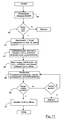
- FIG 11 shows a schematic flow chart of the operation of a pulse delivery process controlled by the control unit 3 (see Figure 10) according to a preferred embodiment of the invention.
- the required pulse parameters are given manually or by reading a memory card (not shown).
- the ohmic resistance of the cuvette is first measured by short-term application of a low voltage (eg 12 V) to the cuvette terminals 15,18 and a subsequent current measurement (eg for 2 ms) in step 44 , In the context of the query 45 is checked whether this resistance is within a given window. Otherwise, the rest of the process will be aborted.
- the measured resistance value is not further used for the calculation of the charging voltage U 2 in the present embodiment of the invention.
- the memory devices 7, 8 are charged in step 46 to the predetermined voltages U 1 and U 2 .
- the charging is switched off by the HV power supply units 5, 6.
- the pulse delivery for the high voltage pulse then begins in step 47 by closing the semiconductor switch 9. This causes a relatively high current to flow through the cuvette. Too steep a rise of the current is detected by an overcurrent cut-off stage 20 and leads for safety reasons to an immediate opening of the switch 9 and a termination of the routine.
- the high voltage pulse is terminated after a predetermined period of a few microseconds, followed immediately and without interruption by the second pulse.
- step 48 the second semiconductor switch 10 already closed a short time before opening the first semiconductor switch 9, so that there is an interruption-free transition between the two pulses.
- the diode 17 prevents a possibly higher voltage from flowing from the memory device 7 into the memory device 8.
- the semiconductor switch 10 then remains open (as long as the maximum current is not exceeded by a Kochstromabschaltwork 22) until the predetermined charge Q has flowed through the cuvette.
- the current flowing through the cuvette is measured and integrated in step 49 at predetermined time intervals (eg 1 ms). As soon as the predetermined target charge has been reached (compare question 50), the switch 10 is opened and the routine is ended.
- the capacity of the memory device 8 is chosen so that the voltage drops gradually during the duration of the second pulse. If, due to a fault, the predetermined target charge is still not reached, even if the storage device is almost completely discharged, the process is also aborted after exceeding a correspondingly selected time limit.
Landscapes
- Health & Medical Sciences (AREA)
- Life Sciences & Earth Sciences (AREA)
- Engineering & Computer Science (AREA)
- Genetics & Genomics (AREA)
- Biomedical Technology (AREA)
- Bioinformatics & Cheminformatics (AREA)
- General Health & Medical Sciences (AREA)
- Organic Chemistry (AREA)
- Wood Science & Technology (AREA)
- Zoology (AREA)
- Chemical & Material Sciences (AREA)
- Biophysics (AREA)
- Biotechnology (AREA)
- General Engineering & Computer Science (AREA)
- Nuclear Medicine, Radiotherapy & Molecular Imaging (AREA)
- Veterinary Medicine (AREA)
- Public Health (AREA)
- Animal Behavior & Ethology (AREA)
- Radiology & Medical Imaging (AREA)
- Microbiology (AREA)
- Biochemistry (AREA)
- Physics & Mathematics (AREA)
- Plant Pathology (AREA)
- Molecular Biology (AREA)
- Apparatus Associated With Microorganisms And Enzymes (AREA)
- Micro-Organisms Or Cultivation Processes Thereof (AREA)
- Immobilizing And Processing Of Enzymes And Microorganisms (AREA)
Abstract
Description
- FACS
- Flurorescence activated cell sorting
- FCS
- foetales Kälberserum
- PBMC
- periphere mononukleäre Blutzellen
- PE
- Phycoerythrin
Es zeigt
- Figur 1
- eine Transfektion von zytotoxischen T-Zellen aus menschlichem Blut
- Figur 2
- eine Transfektion von pluripotenten Vorläuferzellen des menschlichen Bluts
- Figur 3
- eine Transfektion von menschlichen neonatalen dermalen Fibroblasten
- Figur 4
- eine Transfektion von menschlichen neonatalen dermalen Melanozyten
- Figur 5
- eine Transfektion menschlicher Endothelzellen aus der Nabelschnurvene
- Figur 6
- eine Transfektion der Zelllinie K562 (Analyse 4h nach Transfektion)
- Figur 7
- eine Untersuchung der Effizienz der Transfektion in Abhängigkeit von Stromstärke, lmpulszeit und Ladungsmenge und der Intensität der Expression in Abhängigkeit von der Ladungsmenge, Versuch mit der Zelllinie CHO
- Figur 8
- eine Untersuchung der Effizienz der Transfektion in Abhängigkeit von Stromstärke, lmpulszeit und Ladungsmenge und der Intensität der Expression in Abhängigkeit von der Ladungsmenge, Versuch mit der Zelllinie Jurkat
- Figur 9
- eine Untersuchung der Effizienz der Transfektion in Abhängigkeit von Stromstärke, lmpulszeit und Ladungsmenge und der Intensität der Expression in Abhängigkeit von der Ladungsmenge, Versuch mit der Zelllinie Jurkat und dem Oberflächenmarkerprotein H-2Kk.
- Figur 10
- ein Blockschaltbild einer Elektroporatorschaltung,
- Figur 11
- ein Flussdiagramm zur Erläuterung des Ablaufs der lmpulsabgabevorgänge.
- 1
- Elektroporator
- 2
- Einstellungseinheit
- 3
- Steuerungseinheit
- 4
- Spannungsversorgungseinheit
- 5
- HV-Netzteil
- 6
- HV-Netzteil
- 7
- Speichereinrichtung
- 8
- Speichereinrichtung
- 9
- Leistungshalbleiter
- 10
- Leistungshalbleiter
- 11
- Potentialtrennstufe
- 12
- Potentialtrennstufe
- 13
- HV-Schalter
- 14
- Regelungseinheit
- 15
- Küvettenanschluss
- 16
- Widerstand
- 17
- Diode
- 18
- Küvettenanschluss
- 19
- Widerstand
- 20
- Überstromabschaltstufe
- 21
- Schalter
- 22
- Überstromabschaltstufe
- 23
- Schalter
- 30
- Tastschalter
- 31
- Anzeigelement
- 32
- LED
- 33
- Anschlussstecker
- 34
- Kartenleser
- 35
- Umschalter
- 36
- Transformator
- 37
- Gleichrichter
- 38
- SpannungsRegeler
- 39
- Regelstufe
- 40
- Transformatorstufe
- 41
- Lötpad
- 42
- Lötpad
- 43
- lmpulskontrollstufe
- 44
- bis 51 Schritte
Claims (15)
- Verfahren zur Einbringung von Nukleinsäuren, Peptiden, Proteinen und/oder anderen biologisch aktiven Molekülen in den Zellkern eukaryontischer Zellen mittels elektrischen Stroms, wobei zumindest ein Spannungsimpuls auf die Zellen übertragen wird, dadurch gekennzeichnet, dass die durch den Spannungsimpuls abgegebene Ladungsmenge in zumindest einem wählbaren Zeitintervall gemessen wird, wobei ein Vergleich einer voreingestellten Soll-Ladungsmenge mit der abgegebenen Ist-Ladungsmenge durchgeführt wird, und dass bei Erreichen oder Überschreiten der Soll-Ladungsmenge der Spannungsimpuls abgebrochen wird.
- Verfahren nach Anspruch 1, dadurch gekennzeichnet, dass zunächst ein erster Impuls mit der Spannung U1 auf die Zellen übertragen wird und dass anschließend ohne Unterbrechung zumindest ein zweiter Impuls mit der Spannung U2 ebenfalls auf die Zellen übertragen wird.
- Verfahren nach Anspruch 1 oder 2, dadurch gekennzeichnet, dass die Bestimmung der abgegebenen Ladungsmenge aus der Differenz zwischen der ursprünglichen Ladung einer entsprechenden Speichereinrichtung (7,8) und der restlichen Ladung erfolgt.
- Verfahren nach einem oder mehreren der Ansprüche 1 - 3, dadurch gekennzeichnet, dass ein erster Impuls mit einer Feldstärke von 2 - 10 kV/cm und mit einer Dauer von 10 - 100 µs und einer Stromdichte von mindestens 2 A cm-2 und anschließend ohne Unterbrechung ein zweiter Impuls mit einer Stromdichte von 2 - 14 A cm-2 und einer Dauer von maximal 100 ms auf die Zellen übertragen wird.
- Verfahren nach einem oder mehreren der Ansprüche 1 - 4, dadurch gekennzeichnet, dass das Zeitintervall zur Bestimmung der abgegebenen Ladung zeitgleich mit der Abgabe der Ladung des ersten und/oder vorzugsweise eines zweiten oder jeden weiteren Impulses festgelegt wird.
- Verfahren nach einem oder mehreren der Ansprüche 1 - 5, dadurch gekennzeichnet, dass die Einschaltdauer (T2) des zweiten Impulses durch einen Vergleich der Soll-Ladungsmenge mit der bis zum Messzeitpunkt abgegebenen Ist-Ladungsmenge festgelegt wird und mit Erreichen der Soll-Ladungsmenge beendet wird.
- Verfahren nach einem oder mehreren der Ansprüche 1 - 6, dadurch gekennzeichnet, dass zur Bestimmung der Ist-Ladungsmenge ein Messzyklus von 1 msec gewählt wird, wobei während der Zeit (T2) die Kondensatorspannung exponentiell abfällt und der Impuls bei Erreichen der festgelegten Ladungsmenge (Q2) abgebrochen wird.
- Verfahren nach einem oder mehreren der Ansprüche 1 - 7, dadurch gekennzeichnet, dass nach zumindest einem vorbestimmten Zeitintervall nach Auslösen eines ersten und/oder zweiten Impulses der fließende Strom gemessen wird und bei Über- oder Unterschreiten eines Sollwertes die Dauer des Pulses nachgeregelt wird, um die abgegebene Ladungsmenge konstant zu halten.
- Verfahren nach einem oder mehreren der Ansprüche 1 - 7, dadurch gekennzeichnet, dass nach zumindest einem vorbestimmten Zeitintervall nach Auslösen eines ersten und/oder zweiten Impulses der fließende Strom gemessen wird und bei Über- oder Unterschreiten eines Sollwertes eine Fehlermeldung erfolgt.
- Verfahren nach einem oder mehreren der Ansprüche 1 - 7, dadurch gekennzeichnet, dass nach zumindest einem vorbestimmten Zeitintervall nach Auslösen eines ersten und/oder zweiten Impulses der fließende Strom gemessen wird und bei Über- oder Unterschreiten des Sollwertes eine Nachregelung an den Sollwert erfolgt.
- Verfahren nach einem oder mehreren der Ansprüche 1 - 10, dadurch gekennzeichnet, dass vorselektierte Einstellungsparameter der Impulse (U1, T1, I2, T2, K2) manuell oder über die Eingabe eines Codes eingegeben werden.
- Verfahren nach einem oder mehreren der Ansprüche 1 - 11, dadurch gekennzeichnet, dass eine Überstromabschaltung für den ersten und den zweiten Impuls durchgeführt wird.
- Verfahren nach einem oder mehreren der Ansprüche 1 - 12, dadurch gekennzeichnet, dass der für die Berechnung von U2 verwendete Widerstand R einer Küvette durch eine Widerstandsmessung vor Ansteuerung eines Leistungshalbleiters (9, 19) ermittelt wird.
- Verfahren nach einem oder mehreren der Ansprüche 1 - 12, dadurch gekennzeichnet, dass der für die Berechnung von U2 verwendete Widerstand R der Küvette vorgegeben wird.
- Verfahren nach einem oder mehreren der Ansprüche 1 - 14, dadurch gekennzeichnet, dass vorselektierte Einstellungsparameter der Impulse (U1, T1, I2, T2, K2, R) über eine Speicherkarte eingelesen werden.
Applications Claiming Priority (3)
| Application Number | Priority Date | Filing Date | Title |
|---|---|---|---|
| DE10119901 | 2001-04-23 | ||
| DE10119901A DE10119901A1 (de) | 2001-04-23 | 2001-04-23 | Schaltungsanordnung zur Einbringung von Nukleinsäuren und anderen biologisch aktiven Molekülen in den Kern höherer eukaryontischer Zellen mit Hilfe elektrischen Stroms |
| EP02740285A EP1383901B1 (de) | 2001-04-23 | 2002-04-23 | Schaltungsanordnung zur einbringung von nukleinsäuren und anderen biologisch aktiven molekülen in den kern höherer eukaryontischer zellen mit hilfe elektrischen stroms |
Related Parent Applications (1)
| Application Number | Title | Priority Date | Filing Date |
|---|---|---|---|
| EP02740285A Division EP1383901B1 (de) | 2001-04-23 | 2002-04-23 | Schaltungsanordnung zur einbringung von nukleinsäuren und anderen biologisch aktiven molekülen in den kern höherer eukaryontischer zellen mit hilfe elektrischen stroms |
Publications (3)
| Publication Number | Publication Date |
|---|---|
| EP1522587A2 true EP1522587A2 (de) | 2005-04-13 |
| EP1522587A3 EP1522587A3 (de) | 2005-06-08 |
| EP1522587B1 EP1522587B1 (de) | 2008-04-02 |
Family
ID=7682433
Family Applications (2)
| Application Number | Title | Priority Date | Filing Date |
|---|---|---|---|
| EP04024956A Expired - Lifetime EP1522587B1 (de) | 2001-04-23 | 2002-04-23 | Verfahren zur Einbringung von Nukleinsäuren und anderen biologisch aktiven Molekülen in den Kern höherer eukaryontischer Zellen mit Hilfe elektrischen Stroms |
| EP02740285A Expired - Lifetime EP1383901B1 (de) | 2001-04-23 | 2002-04-23 | Schaltungsanordnung zur einbringung von nukleinsäuren und anderen biologisch aktiven molekülen in den kern höherer eukaryontischer zellen mit hilfe elektrischen stroms |
Family Applications After (1)
| Application Number | Title | Priority Date | Filing Date |
|---|---|---|---|
| EP02740285A Expired - Lifetime EP1383901B1 (de) | 2001-04-23 | 2002-04-23 | Schaltungsanordnung zur einbringung von nukleinsäuren und anderen biologisch aktiven molekülen in den kern höherer eukaryontischer zellen mit hilfe elektrischen stroms |
Country Status (15)
| Country | Link |
|---|---|
| US (2) | US8173416B2 (de) |
| EP (2) | EP1522587B1 (de) |
| JP (2) | JP4124659B2 (de) |
| KR (1) | KR100810173B1 (de) |
| CN (1) | CN1257979C (de) |
| AT (2) | ATE281529T1 (de) |
| AU (1) | AU2007202279B2 (de) |
| CA (1) | CA2445257C (de) |
| DE (4) | DE10119901A1 (de) |
| ES (2) | ES2305642T3 (de) |
| IL (2) | IL158513A0 (de) |
| MX (1) | MXPA03009666A (de) |
| NO (1) | NO20034681L (de) |
| WO (1) | WO2002086129A1 (de) |
| ZA (1) | ZA200308254B (de) |
Families Citing this family (23)
| Publication number | Priority date | Publication date | Assignee | Title |
|---|---|---|---|---|
| ES2465467T3 (es) * | 2004-06-14 | 2014-06-05 | Lonza Cologne Ag | Procedimiento y disposición de circuito para el tratamiento de material biológico |
| EP1859028B1 (de) * | 2005-02-10 | 2015-12-02 | Regents Of The University Of Minnesota | Vaskuläre Endothelzellen |
| US8278104B2 (en) | 2005-12-13 | 2012-10-02 | Kyoto University | Induced pluripotent stem cells produced with Oct3/4, Klf4 and Sox2 |
| US20090227032A1 (en) | 2005-12-13 | 2009-09-10 | Kyoto University | Nuclear reprogramming factor and induced pluripotent stem cells |
| US8129187B2 (en) | 2005-12-13 | 2012-03-06 | Kyoto University | Somatic cell reprogramming by retroviral vectors encoding Oct3/4. Klf4, c-Myc and Sox2 |
| CN101864392B (zh) | 2005-12-13 | 2016-03-23 | 国立大学法人京都大学 | 核重新编程因子 |
| WO2007081631A2 (en) * | 2006-01-04 | 2007-07-19 | Healtheuniverse, Inc. | Method of producing insulin-secreting cells from adult stem cells via transfection |
| DE102007005909A1 (de) | 2007-02-01 | 2008-08-14 | Amaxa Ag | Verfahren zur Kontrolle eines mit Elektroden versehenen Behältnissen |
| JP2008307007A (ja) | 2007-06-15 | 2008-12-25 | Bayer Schering Pharma Ag | 出生後のヒト組織由来未分化幹細胞から誘導したヒト多能性幹細胞 |
| US9213999B2 (en) | 2007-06-15 | 2015-12-15 | Kyoto University | Providing iPSCs to a customer |
| EP2754445A3 (de) * | 2007-09-28 | 2014-08-27 | Johnson & Johnson Consumer Companies Inc. | Stromerzeugende Teilchen zur Behandlung von exzessivem Schwitzen |
| CN101855350B (zh) | 2008-05-02 | 2014-12-31 | 国立大学法人京都大学 | 核重编程序方法 |
| EP2208778A1 (de) | 2009-01-20 | 2010-07-21 | Lonza Cologne AG | Verfahren und Vorrichtung zur elektrischen Behandlung von Reaktionsräumen |
| US20140099284A1 (en) | 2010-10-15 | 2014-04-10 | Eos Neuroscience, Inc | Modulation neural pathways |
| WO2012098260A1 (en) | 2011-01-21 | 2012-07-26 | Axiogenesis Ag | A non-viral system for the generation of induced pluripotent stem (ips) cells |
| US10421956B2 (en) | 2014-01-17 | 2019-09-24 | General Electric Company | Electric pulse generation systems using capacitive coupling |
| US9452199B2 (en) | 2014-01-17 | 2016-09-27 | General Electric Company | Platelet activation and growth factor release using electric pulses |
| US9708597B2 (en) * | 2014-01-17 | 2017-07-18 | General Electric Company | Electric pulse generation systems using capacitive coupling |
| US10093706B2 (en) | 2017-01-30 | 2018-10-09 | Indiana University Research And Technology Corporation | Dominant positive hnRNP-E1 polypeptide compositions and methods |
| JP6518971B2 (ja) * | 2017-05-12 | 2019-05-29 | 株式会社ベックス | エレクトロポレーター用電源 |
| US10968423B2 (en) | 2018-02-26 | 2021-04-06 | General Electric Company | System and method for electric pulse based activation of biological samples |
| WO2021010341A1 (ja) * | 2019-07-12 | 2021-01-21 | 富士フイルム株式会社 | 生体由来物の製造方法、産生物の製造方法及び電圧印加装置 |
| EP4058134A1 (de) * | 2020-03-26 | 2022-09-21 | St Andrews Pharmaceutical Technology Ltd. | Vorrichtung zur verbesserten transfektionseffizienz und/oder proteinexpression und verfahren zur verwendung davon |
Family Cites Families (42)
| Publication number | Priority date | Publication date | Assignee | Title |
|---|---|---|---|---|
| US3707974A (en) | 1970-12-11 | 1973-01-02 | W Raddi | Body organ stimulator with voltage converter |
| US4849355A (en) | 1985-01-08 | 1989-07-18 | Wong Tai Kin | Method of transferring genes into cells |
| GB8332507D0 (en) | 1982-12-10 | 1984-01-11 | Trolex Prod Ltd | Impedance sensor |
| US4923814A (en) | 1986-05-09 | 1990-05-08 | Electropore, Inc. | High speed, high power apparatus for vesicle prealignment, poration, loading and fusion in uniform electric fields and method therefor |
| US4946793A (en) | 1986-05-09 | 1990-08-07 | Electropore, Inc. | Impedance matching for instrumentation which electrically alters vesicle membranes |
| US4906576A (en) | 1986-05-09 | 1990-03-06 | Electropore, Inc. | High speed, high power apparatus for vesicle prealignment, poration, loading and fusion in uniform electric fields and method therefor |
| US4750100A (en) * | 1986-06-06 | 1988-06-07 | Bio-Rad Laboratories | Transfection high voltage controller |
| CH668984A5 (de) | 1986-10-10 | 1989-02-15 | Electropore Inc | Verfahren zur gewinnung von zellinhaltsstoffen. |
| JPH0436637Y2 (de) * | 1986-10-14 | 1992-08-28 | ||
| DE3708775A1 (de) | 1987-03-18 | 1988-09-29 | Heinz Doevenspeck | Verfahren und vorrichtung zur behandlung von stoffen und/oder mikro-organismen mit elektroimpulsen |
| US5098843A (en) | 1987-06-04 | 1992-03-24 | Calvin Noel M | Apparatus for the high efficiency transformation of living cells |
| DE3724291A1 (de) * | 1987-07-22 | 1989-02-02 | Siemens Ag | Geregelte kurzzeit-energiequelle |
| US5128257A (en) | 1987-08-31 | 1992-07-07 | Baer Bradford W | Electroporation apparatus and process |
| GB8807271D0 (en) | 1988-03-26 | 1988-04-27 | Preece A W | Cell fusion apparatus |
| JP2621384B2 (ja) | 1988-07-22 | 1997-06-18 | 株式会社島津製作所 | 時定数制御型細胞電気刺激装置 |
| US5002052A (en) * | 1988-08-29 | 1991-03-26 | Intermedics, Inc. | System and method for detection and treatment of ventricular arrhythmias |
| CA1327174C (en) | 1988-10-05 | 1994-02-22 | Youssef Mouneimne | Electro-insertion of proteins into animal cell membranes |
| JPH02303478A (ja) | 1989-05-19 | 1990-12-17 | Kirin Brewery Co Ltd | 遺伝子導入装置 |
| JPH03195485A (ja) | 1989-12-25 | 1991-08-27 | Kazuo Yanagi | エレクトロポレーション装置 |
| BE1004328A3 (fr) | 1990-05-16 | 1992-11-03 | Scient Equipment Design & Dev | Procede et dispositif de permeabilisation de cellules vivantes. |
| CA2019758C (en) | 1990-06-25 | 2001-09-04 | Kevin L. Firth | Improved electroporation device and method |
| AU8856091A (en) | 1990-09-27 | 1992-04-28 | United States of America, as represented by the Secretary, U.S. Department of Commerce, The | Method of electroporation using bipolar oscillating electric fields |
| US5254081A (en) | 1991-02-01 | 1993-10-19 | Empi, Inc. | Multiple site drug iontophoresis electronic device and method |
| US5273525A (en) | 1992-08-13 | 1993-12-28 | Btx Inc. | Injection and electroporation apparatus for drug and gene delivery |
| US5627023A (en) | 1993-03-29 | 1997-05-06 | Duke University | Suppressor of HIV replication and transcription |
| US5422272A (en) | 1993-07-14 | 1995-06-06 | Andrew A. Papp | Improvements to apparatus and method for electroporation |
| JP3195485B2 (ja) | 1993-12-27 | 2001-08-06 | 大塚化学株式会社 | 難燃剤組成物の製造方法及び難燃化方法 |
| US5642035A (en) | 1994-06-16 | 1997-06-24 | Bio-Rad Laboratories | Transfection high-voltage controller |
| JPH10503643A (ja) | 1994-06-17 | 1998-04-07 | ネーデルランセ オルハニサチエ フォール トゥーヘパスト−ナツールウェーテンシャッペルック オンデルズク テーエヌオー | 微生物中に遺伝物質を導入する方法およびその方法によってえられる形質転換体 |
| US6103084A (en) * | 1995-06-06 | 2000-08-15 | Eppendorf Netheler-Hinz Gmbh | Apparatus for electroporation |
| US5905371A (en) * | 1995-06-23 | 1999-05-18 | D.C. Transformation, Inc. | Sequential discharge and its use for rectification |
| US5869326A (en) * | 1996-09-09 | 1999-02-09 | Genetronics, Inc. | Electroporation employing user-configured pulsing scheme |
| EP0866123B1 (de) | 1997-03-21 | 2005-03-16 | Eppendorf Ag | Verfahren und Schaltungsanordnung zur Elektropermeation oder Elektroporation von lebenden Zellen |
| US6117660A (en) * | 1997-06-10 | 2000-09-12 | Cytopulse Sciences, Inc. | Method and apparatus for treating materials with electrical fields having varying orientations |
| SE9704076D0 (sv) | 1997-11-06 | 1997-11-06 | Holdingbolaget Vid Goeteborgs | Method for permeabilisation of cell structures and use thereof |
| WO1999036563A1 (en) | 1998-01-14 | 1999-07-22 | Emed Corporation | Electrically mediated cellular expression |
| WO2000011155A1 (en) | 1998-08-19 | 2000-03-02 | The Board Of Trustees Of The Leland Stanford Junior University | Methods and compositions for genomic modification |
| US6040184A (en) * | 1998-10-09 | 2000-03-21 | Stratagene | Method for more efficient electroporation |
| US6150148A (en) | 1998-10-21 | 2000-11-21 | Genetronics, Inc. | Electroporation apparatus for control of temperature during the process |
| US6678558B1 (en) * | 1999-03-25 | 2004-01-13 | Genetronics, Inc. | Method and apparatus for reducing electroporation-mediated muscle reaction and pain response |
| US6366808B1 (en) * | 2000-03-13 | 2002-04-02 | Edward A. Schroeppel | Implantable device and method for the electrical treatment of cancer |
| US6258592B1 (en) | 1999-06-14 | 2001-07-10 | Bio-Rad Laboratories, Inc. | Electroporation cell with arc prevention/reduction |
-
2001
- 2001-04-23 DE DE10119901A patent/DE10119901A1/de not_active Withdrawn
-
2002
- 2002-04-23 IL IL15851302A patent/IL158513A0/xx unknown
- 2002-04-23 ES ES04024956T patent/ES2305642T3/es not_active Expired - Lifetime
- 2002-04-23 DE DE10291733T patent/DE10291733D2/de not_active Expired - Fee Related
- 2002-04-23 CA CA2445257A patent/CA2445257C/en not_active Expired - Lifetime
- 2002-04-23 US US10/475,840 patent/US8173416B2/en active Active
- 2002-04-23 DE DE50212037T patent/DE50212037D1/de not_active Expired - Lifetime
- 2002-04-23 WO PCT/DE2002/001489 patent/WO2002086129A1/de not_active Ceased
- 2002-04-23 EP EP04024956A patent/EP1522587B1/de not_active Expired - Lifetime
- 2002-04-23 AT AT02740285T patent/ATE281529T1/de active
- 2002-04-23 JP JP2002583643A patent/JP4124659B2/ja not_active Expired - Lifetime
- 2002-04-23 ES ES02740285T patent/ES2231709T3/es not_active Expired - Lifetime
- 2002-04-23 MX MXPA03009666A patent/MXPA03009666A/es unknown
- 2002-04-23 CN CNB028086503A patent/CN1257979C/zh not_active Expired - Lifetime
- 2002-04-23 KR KR1020037013815A patent/KR100810173B1/ko not_active Expired - Lifetime
- 2002-04-23 DE DE50201472T patent/DE50201472D1/de not_active Expired - Lifetime
- 2002-04-23 EP EP02740285A patent/EP1383901B1/de not_active Expired - Lifetime
- 2002-04-23 AT AT04024956T patent/ATE391185T1/de active
-
2003
- 2003-10-20 IL IL158513A patent/IL158513A/en not_active IP Right Cessation
- 2003-10-20 NO NO20034681A patent/NO20034681L/no not_active Application Discontinuation
- 2003-10-23 ZA ZA200308254A patent/ZA200308254B/xx unknown
-
2007
- 2007-05-21 AU AU2007202279A patent/AU2007202279B2/en not_active Expired
- 2007-08-09 US US11/836,656 patent/US20090023131A1/en not_active Abandoned
-
2008
- 2008-03-03 JP JP2008052215A patent/JP4694587B2/ja not_active Expired - Lifetime
Also Published As
Similar Documents
| Publication | Publication Date | Title |
|---|---|---|
| EP1522587B1 (de) | Verfahren zur Einbringung von Nukleinsäuren und anderen biologisch aktiven Molekülen in den Kern höherer eukaryontischer Zellen mit Hilfe elektrischen Stroms | |
| EP1390518B1 (de) | Pufferlössung für die elektroporation und verfahren umfassend die verwendung derselben | |
| DE69711893T2 (de) | Elektroporationsgerät mit benutzerkonfigurierten impulsen | |
| EP1607484B1 (de) | Verfahren und Schaltungsanordnung zur Behandlung von biologischem Material | |
| DE10202094B4 (de) | Verfahren und Vorrichtung zur Elektroporation biologischer Zellen | |
| DE69218658T2 (de) | Implantierbares Defibrillator-System | |
| EP2399985B1 (de) | Verfahren und Vorrichtung zur gleichmässigen Behandlung von adhärenten Zellen | |
| DE69926501T2 (de) | Vergrösserung der muskelkontraktionskraft durch zweiphasige reizung | |
| DE69510769T2 (de) | Verfahren zur regelung der ladung eines elektrischen akkumulatorsystemes und vorrichtung zur durchführung dieses verfahrens | |
| DE60038026T2 (de) | Methode zur intrazellulären elektro-manipulation | |
| EP1448264B1 (de) | Retina-implantat mit elektrodenanordnung zur elektrischen stimulation von biologischem material | |
| DE2946729A1 (de) | Geraet zum zerstoeren von gewebeteilen | |
| WO2003070875A2 (de) | Behälter mit zumindest einer elektrode | |
| EP1297119B9 (de) | Verfahren zur einbringung von nukleinsäuren und anderen biologisch aktiven molekülen in den kern höherer eukaryontischer zellen mit hilfe elektrischen stroms | |
| US8248050B2 (en) | Multi-channel low voltage micro-electric-field generator | |
| EP1188827B1 (de) | Verfahren zur Fusion von dendritischen Zellen mit Tumorzellen und Medien für solche Verfahren | |
| DE102008024803B4 (de) | Vorrichtung und Verfahren zur Bestimmung von Resonanzfrequenzen einer Zellprobe | |
| DE2216629A1 (de) | Pulsbreitengesteuerter herzschrittmacher | |
| CH715327A2 (de) | Elektrotherapie-Vorrichtung zur Zelltherapie oder Zellstimulation. | |
| Klein et al. | The influence of naproxen on DNA-synthesis and DNA-repair in human lymphocytes |
Legal Events
| Date | Code | Title | Description |
|---|---|---|---|
| PUAI | Public reference made under article 153(3) epc to a published international application that has entered the european phase |
Free format text: ORIGINAL CODE: 0009012 |
|
| AC | Divisional application: reference to earlier application |
Ref document number: 1383901 Country of ref document: EP Kind code of ref document: P |
|
| AK | Designated contracting states |
Kind code of ref document: A2 Designated state(s): AT BE CH CY DE DK ES FI FR GB GR IE IT LI LU MC NL PT SE TR |
|
| PUAL | Search report despatched |
Free format text: ORIGINAL CODE: 0009013 |
|
| AK | Designated contracting states |
Kind code of ref document: A3 Designated state(s): AT BE CH CY DE DK ES FI FR GB GR IE IT LI LU MC NL PT SE TR |
|
| 17P | Request for examination filed |
Effective date: 20051208 |
|
| AKX | Designation fees paid |
Designated state(s): AT BE CH CY DE DK ES FI FR GB GR IE IT LI LU MC NL PT SE TR |
|
| RAP1 | Party data changed (applicant data changed or rights of an application transferred) |
Owner name: AMAXA AG |
|
| GRAP | Despatch of communication of intention to grant a patent |
Free format text: ORIGINAL CODE: EPIDOSNIGR1 |
|
| GRAS | Grant fee paid |
Free format text: ORIGINAL CODE: EPIDOSNIGR3 |
|
| GRAA | (expected) grant |
Free format text: ORIGINAL CODE: 0009210 |
|
| AC | Divisional application: reference to earlier application |
Ref document number: 1383901 Country of ref document: EP Kind code of ref document: P |
|
| AK | Designated contracting states |
Kind code of ref document: B1 Designated state(s): AT BE CH CY DE DK ES FI FR GB GR IE IT LI LU MC NL PT SE TR |
|
| REG | Reference to a national code |
Ref country code: GB Ref legal event code: FG4D Free format text: NOT ENGLISH |
|
| REG | Reference to a national code |
Ref country code: CH Ref legal event code: EP Ref country code: IE Ref legal event code: FG4D Free format text: LANGUAGE OF EP DOCUMENT: GERMAN |
|
| REF | Corresponds to: |
Ref document number: 50212037 Country of ref document: DE Date of ref document: 20080515 Kind code of ref document: P |
|
| REG | Reference to a national code |
Ref country code: CH Ref legal event code: NV Representative=s name: LUCHS & PARTNER PATENTANWAELTE |
|
| REG | Reference to a national code |
Ref country code: SE Ref legal event code: TRGR |
|
| REG | Reference to a national code |
Ref country code: IE Ref legal event code: FD4D |
|
| PG25 | Lapsed in a contracting state [announced via postgrant information from national office to epo] |
Ref country code: FI Free format text: LAPSE BECAUSE OF FAILURE TO SUBMIT A TRANSLATION OF THE DESCRIPTION OR TO PAY THE FEE WITHIN THE PRESCRIBED TIME-LIMIT Effective date: 20080402 Ref country code: PT Free format text: LAPSE BECAUSE OF FAILURE TO SUBMIT A TRANSLATION OF THE DESCRIPTION OR TO PAY THE FEE WITHIN THE PRESCRIBED TIME-LIMIT Effective date: 20080903 |
|
| REG | Reference to a national code |
Ref country code: ES Ref legal event code: FG2A Ref document number: 2305642 Country of ref document: ES Kind code of ref document: T3 |
|
| RAP2 | Party data changed (patent owner data changed or rights of a patent transferred) |
Owner name: LONZA COLOGNE AG |
|
| PG25 | Lapsed in a contracting state [announced via postgrant information from national office to epo] |
Ref country code: MC Free format text: LAPSE BECAUSE OF NON-PAYMENT OF DUE FEES Effective date: 20080430 |
|
| ET | Fr: translation filed | ||
| PG25 | Lapsed in a contracting state [announced via postgrant information from national office to epo] |
Ref country code: DK Free format text: LAPSE BECAUSE OF FAILURE TO SUBMIT A TRANSLATION OF THE DESCRIPTION OR TO PAY THE FEE WITHIN THE PRESCRIBED TIME-LIMIT Effective date: 20080402 Ref country code: IE Free format text: LAPSE BECAUSE OF FAILURE TO SUBMIT A TRANSLATION OF THE DESCRIPTION OR TO PAY THE FEE WITHIN THE PRESCRIBED TIME-LIMIT Effective date: 20080402 |
|
| PLBE | No opposition filed within time limit |
Free format text: ORIGINAL CODE: 0009261 |
|
| STAA | Information on the status of an ep patent application or granted ep patent |
Free format text: STATUS: NO OPPOSITION FILED WITHIN TIME LIMIT |
|
| 26N | No opposition filed |
Effective date: 20090106 |
|
| PG25 | Lapsed in a contracting state [announced via postgrant information from national office to epo] |
Ref country code: CY Free format text: LAPSE BECAUSE OF FAILURE TO SUBMIT A TRANSLATION OF THE DESCRIPTION OR TO PAY THE FEE WITHIN THE PRESCRIBED TIME-LIMIT Effective date: 20080402 |
|
| NLT1 | Nl: modifications of names registered in virtue of documents presented to the patent office pursuant to art. 16 a, paragraph 1 |
Owner name: LONZA COLOGNE AG |
|
| REG | Reference to a national code |
Ref country code: CH Ref legal event code: PFA Owner name: LONZA COLOGNE AG Free format text: AMAXA AG#NATTERMANNALLEE 1#50829 KOELN (DE) -TRANSFER TO- LONZA COLOGNE AG#NATTERMANNALLEE 1#50829 KOELN (DE) |
|
| PG25 | Lapsed in a contracting state [announced via postgrant information from national office to epo] |
Ref country code: LU Free format text: LAPSE BECAUSE OF NON-PAYMENT OF DUE FEES Effective date: 20080423 |
|
| PG25 | Lapsed in a contracting state [announced via postgrant information from national office to epo] |
Ref country code: TR Free format text: LAPSE BECAUSE OF FAILURE TO SUBMIT A TRANSLATION OF THE DESCRIPTION OR TO PAY THE FEE WITHIN THE PRESCRIBED TIME-LIMIT Effective date: 20080402 |
|
| PG25 | Lapsed in a contracting state [announced via postgrant information from national office to epo] |
Ref country code: GR Free format text: LAPSE BECAUSE OF FAILURE TO SUBMIT A TRANSLATION OF THE DESCRIPTION OR TO PAY THE FEE WITHIN THE PRESCRIBED TIME-LIMIT Effective date: 20080703 |
|
| PG25 | Lapsed in a contracting state [announced via postgrant information from national office to epo] |
Ref country code: IT Free format text: LAPSE BECAUSE OF NON-PAYMENT OF DUE FEES Effective date: 20090423 |
|
| REG | Reference to a national code |
Ref country code: CH Ref legal event code: PFA Owner name: LONZA COLOGNE GMBH Free format text: LONZA COLOGNE AG#NATTERMANNALLEE 1#50829 KOELN (DE) -TRANSFER TO- LONZA COLOGNE GMBH#NATTERMANNALLEE 1#50829 KOELN (DE) |
|
| REG | Reference to a national code |
Ref country code: NL Ref legal event code: TD Effective date: 20110404 |
|
| REG | Reference to a national code |
Ref country code: ES Ref legal event code: PC2A Owner name: LONZA COLOGNE GMBH Effective date: 20110627 |
|
| PGRI | Patent reinstated in contracting state [announced from national office to epo] |
Ref country code: IT Effective date: 20110616 |
|
| REG | Reference to a national code |
Ref country code: FR Ref legal event code: CD |
|
| REG | Reference to a national code |
Ref country code: AT Ref legal event code: PC Ref document number: 391185 Country of ref document: AT Kind code of ref document: T Owner name: LONZA COLOGNE GMBH, DE Effective date: 20120920 |
|
| REG | Reference to a national code |
Ref country code: FR Ref legal event code: PLFP Year of fee payment: 15 |
|
| REG | Reference to a national code |
Ref country code: FR Ref legal event code: PLFP Year of fee payment: 16 |
|
| REG | Reference to a national code |
Ref country code: FR Ref legal event code: PLFP Year of fee payment: 17 |
|
| PGFP | Annual fee paid to national office [announced via postgrant information from national office to epo] |
Ref country code: IT Payment date: 20210331 Year of fee payment: 20 |
|
| PGFP | Annual fee paid to national office [announced via postgrant information from national office to epo] |
Ref country code: BE Payment date: 20210331 Year of fee payment: 20 |
|
| PGFP | Annual fee paid to national office [announced via postgrant information from national office to epo] |
Ref country code: DE Payment date: 20210330 Year of fee payment: 20 Ref country code: FR Payment date: 20210408 Year of fee payment: 20 |
|
| PGFP | Annual fee paid to national office [announced via postgrant information from national office to epo] |
Ref country code: AT Payment date: 20210330 Year of fee payment: 20 Ref country code: SE Payment date: 20210413 Year of fee payment: 20 Ref country code: GB Payment date: 20210413 Year of fee payment: 20 Ref country code: CH Payment date: 20210413 Year of fee payment: 20 |
|
| PGFP | Annual fee paid to national office [announced via postgrant information from national office to epo] |
Ref country code: NL Payment date: 20210406 Year of fee payment: 20 |
|
| PGFP | Annual fee paid to national office [announced via postgrant information from national office to epo] |
Ref country code: ES Payment date: 20210701 Year of fee payment: 20 |
|
| REG | Reference to a national code |
Ref country code: DE Ref legal event code: R071 Ref document number: 50212037 Country of ref document: DE |
|
| REG | Reference to a national code |
Ref country code: NL Ref legal event code: MK Effective date: 20220422 |
|
| REG | Reference to a national code |
Ref country code: BE Ref legal event code: MK Effective date: 20220423 |
|
| REG | Reference to a national code |
Ref country code: CH Ref legal event code: PL |
|
| REG | Reference to a national code |
Ref country code: GB Ref legal event code: PE20 Expiry date: 20220422 |
|
| REG | Reference to a national code |
Ref country code: SE Ref legal event code: EUG |
|
| REG | Reference to a national code |
Ref country code: AT Ref legal event code: MK07 Ref document number: 391185 Country of ref document: AT Kind code of ref document: T Effective date: 20220423 |
|
| PG25 | Lapsed in a contracting state [announced via postgrant information from national office to epo] |
Ref country code: GB Free format text: LAPSE BECAUSE OF EXPIRATION OF PROTECTION Effective date: 20220422 |
|
| REG | Reference to a national code |
Ref country code: ES Ref legal event code: FD2A Effective date: 20220804 |
|
| PG25 | Lapsed in a contracting state [announced via postgrant information from national office to epo] |
Ref country code: ES Free format text: LAPSE BECAUSE OF EXPIRATION OF PROTECTION Effective date: 20220424 |