EP1522635A2 - Attache rapide pour fixer des outils sur un bras d'excavatrices - Google Patents
Attache rapide pour fixer des outils sur un bras d'excavatrices Download PDFInfo
- Publication number
- EP1522635A2 EP1522635A2 EP04450185A EP04450185A EP1522635A2 EP 1522635 A2 EP1522635 A2 EP 1522635A2 EP 04450185 A EP04450185 A EP 04450185A EP 04450185 A EP04450185 A EP 04450185A EP 1522635 A2 EP1522635 A2 EP 1522635A2
- Authority
- EP
- European Patent Office
- Prior art keywords
- wedge
- coupling
- quick
- support plates
- plates
- Prior art date
- Legal status (The legal status is an assumption and is not a legal conclusion. Google has not performed a legal analysis and makes no representation as to the accuracy of the status listed.)
- Granted
Links
- 230000008878 coupling Effects 0.000 claims abstract description 81
- 238000010168 coupling process Methods 0.000 claims abstract description 81
- 238000005859 coupling reaction Methods 0.000 claims abstract description 81
- 230000000630 rising effect Effects 0.000 claims description 2
- 210000000056 organ Anatomy 0.000 description 4
- 238000010586 diagram Methods 0.000 description 3
- 238000005452 bending Methods 0.000 description 2
- 238000006073 displacement reaction Methods 0.000 description 2
- 238000003780 insertion Methods 0.000 description 2
- 230000037431 insertion Effects 0.000 description 2
- 230000000694 effects Effects 0.000 description 1
- 238000004091 panning Methods 0.000 description 1
- 238000004904 shortening Methods 0.000 description 1
Images


Classifications
-
- E—FIXED CONSTRUCTIONS
- E02—HYDRAULIC ENGINEERING; FOUNDATIONS; SOIL SHIFTING
- E02F—DREDGING; SOIL-SHIFTING
- E02F3/00—Dredgers; Soil-shifting machines
- E02F3/04—Dredgers; Soil-shifting machines mechanically-driven
- E02F3/28—Dredgers; Soil-shifting machines mechanically-driven with digging tools mounted on a dipper- or bucket-arm, i.e. there is either one arm or a pair of arms, e.g. dippers, buckets
- E02F3/36—Component parts
- E02F3/3604—Devices to connect tools to arms, booms or the like
- E02F3/3609—Devices to connect tools to arms, booms or the like of the quick acting type, e.g. controlled from the operator seat
- E02F3/3627—Devices to connect tools to arms, booms or the like of the quick acting type, e.g. controlled from the operator seat with a hook and a longitudinal locking element
-
- E—FIXED CONSTRUCTIONS
- E02—HYDRAULIC ENGINEERING; FOUNDATIONS; SOIL SHIFTING
- E02F—DREDGING; SOIL-SHIFTING
- E02F3/00—Dredgers; Soil-shifting machines
- E02F3/04—Dredgers; Soil-shifting machines mechanically-driven
- E02F3/28—Dredgers; Soil-shifting machines mechanically-driven with digging tools mounted on a dipper- or bucket-arm, i.e. there is either one arm or a pair of arms, e.g. dippers, buckets
- E02F3/36—Component parts
- E02F3/3604—Devices to connect tools to arms, booms or the like
- E02F3/3609—Devices to connect tools to arms, booms or the like of the quick acting type, e.g. controlled from the operator seat
- E02F3/364—Devices to connect tools to arms, booms or the like of the quick acting type, e.g. controlled from the operator seat using wedges
-
- E—FIXED CONSTRUCTIONS
- E02—HYDRAULIC ENGINEERING; FOUNDATIONS; SOIL SHIFTING
- E02F—DREDGING; SOIL-SHIFTING
- E02F3/00—Dredgers; Soil-shifting machines
- E02F3/04—Dredgers; Soil-shifting machines mechanically-driven
- E02F3/28—Dredgers; Soil-shifting machines mechanically-driven with digging tools mounted on a dipper- or bucket-arm, i.e. there is either one arm or a pair of arms, e.g. dippers, buckets
- E02F3/36—Component parts
- E02F3/3604—Devices to connect tools to arms, booms or the like
- E02F3/3609—Devices to connect tools to arms, booms or the like of the quick acting type, e.g. controlled from the operator seat
- E02F3/3663—Devices to connect tools to arms, booms or the like of the quick acting type, e.g. controlled from the operator seat hydraulically-operated
Definitions
- the invention relates to a quick-change coupling for fastening the Work tools on an excavator boom, in which the excavator tool and the excavator boom each a coupling body part is arranged, wherein the two Coupling body parts by a hook connection and acting as a counter-holder Wedge lock with mutual pressure surfaces against each other can be fixed.
- the wedge bar enforce the support plates and on the excavator boom remote from the outside of the Supporting support plates, wherein on both sides of each of the support plates, the spline is provided.
- a hydraulic piston-cylinder unit to be provided the unlocked at Wedge lock is fully extended. This has the advantage that the piston surface, the Locking the wedge connection is available due to the attached Piston rod is lower than to release the wedge lock, whereby a possible Seizing the wedge connection is counteracted so far as when loosening Forces can be applied as when locking.
- the receiving recesses of the Coupling plate with respect to the plane transverse to the plane vertical vertical center plane be formed symmetrically.
- two each Coupling plates may be provided, wherein the support plates in the space between the adjacent coupling plates can be used. This can especially for larger work tools achieved very stable coupling parts on the working tool become.
- the hydraulic piston-cylinder unit with its end facing away from the wedge rod be supported the belonging to the hook connection cross bar.
- Support of the hydraulic piston-cylinder unit towards attachment of the Excavator boom towards bent tabs may be provided opposite to the support plates secured against pivoting.
- the coupling parts protruding from the working tool do not necessarily As shown in Figs. 9 and 11 reproduced, be present several times on each side but it is sufficient for certain application variants also that the vertical Parts are provided on each side of the longitudinal center only individually, it depending on Requirement is possible, the corresponding vertical sections of the coupling part either on the inside or on the outside of the excavator boom ago can be arranged recessed coupling part.
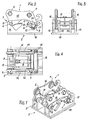
- the change-speed clutch according to the invention has one on the excavator boom fastened coupling part 1 and a to be fastened to the working tool Coupling part 2, wherein the two coupling parts on the one hand via a Hook connection 3 and on the other hand connected via a spline connection 4 are, wherein on both coupling parts additionally cooperating oblique Anlaufand Weglitis 5 are provided which pressed together by the spline connection be so as to achieve a play-free fit of the two coupling parts.
- the excavator boom to be attached to the coupling part 1 has eyelets 6.7, through which push through the fastening bolts for attachment to the excavator boom and can be specified in it.
- a cross bar 8 for engaging in the on the Work tool to be fastened coupling part 2 provided hook provided.
- the Wedge connection is by a parallel to the cross bar 8 extending in the region of Wedge-shaped wedge-shaped, flattened rod 10 is formed, being used as counter surfaces on Coupling part 2 contact surfaces 11 are provided along which the wedge rod 10 so can be moved, that the coupling part 1 pulled into the coupling part 2 becomes.
- the mutual Andschreib vom 5 formed by the fact that on the coupling part 1, a pressure plate 12th is provided, which to corresponding counter-bearing surfaces 13 on the coupling part 2 in Plant can be brought.
- the inclination of the pressure plate 12 corresponds in the coupled state about the inclination of the Gegenandschreib modelling 13, so that upon actuation of the wedge connection a Mutual Verspannen between wedge connection and Andschreibdon is given, the additionally also has the effect that due to the inclination of the pressing surfaces 5 of the cross bar 8 is pressed into the hooks 9.
- a hydraulic piston-cylinder unit 15 is provided, which is arranged so that for insertion of the wedge bar 10 at the corresponding counter wedge surfaces 11, the hydraulic piston-cylinder unit in the sense of shortening the same is pressurized. This has the advantage that for opening a higher pressure can be used as for insertion of the wedge connection, with what possible Deadlocks can be prevented, or these jamming easier solved can be.
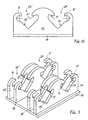
- Keilanlauf requirements 11 and the Jacobsburgsch requirements 13 is to be attached to the working tool coupling part 2 by Clutch plates 14,14 'formed, which with respect to the longitudinal center plane of the Working tool are arranged symmetrically.
- These coupling plates 14,14 ' stand parallel to each other and are attached to a support plate 18. Cross connections to Connection of the plates with each other are not provided.
- the two support plates 16th provided on the one hand, the eyelets 6,7 and on the other hand, the cross bar 8 for hanging of the coupling part 1 in the hook 9 of the coupling part 2, wherein the cross bar. 8 the two support plates 16 connects to each other and these on the outside on both sides surmounted. Furthermore, the two support plates 16, which are also parallel to each other run and symmetrical to the longitudinal center plane of the working tool and also the Knickebene the excavator boom are still arranged by the pressure plate 12th connected with each other.
- a connecting web 17th provided, which is attached via a central tab 20 on the cross bar 8 and of which on the side facing away from the tab 12 two mounting tabs 21 projecting are mounted, between which the hydraulic piston-cylinder unit 15th is pivotally mounted.
- the connecting tab 20 as well as the two Mounting tabs 21 are each cranked to the eyelets 6,7 out, causing the Longitudinal axis of the hydraulic piston-cylinder unit 15 approximately in the direction of movement of the Keilstabes 10 comes to rest.
- the wedge bar 10 is in the support plates 16 via Slots 23 out, and dominates the support plates on both sides of the outside.
- the Wedge surfaces on the wedge bar 10 are both at the between the support plates 16th located, these adjacent areas as well as on the support plates 16 outside provided for outstanding areas.
- the hydraulic piston-cylinder unit 15 engages on the wedge bar 10 in the middle, wherein the wedge rod 10 by a guide plate 22 in the axial Direction is led.
- the connection is made possible by any Wedge movements, e.g. Pivoting about its longitudinal axis, no moments on the hydraulic piston-cylinder unit are transmitted.
- the wedge bar 10 is formed as continuous, wherein it is in the region of Attachment of the hydraulic piston-cylinder unit fully, so circular held, on both sides of the articulation of the hydraulic piston-cylinder unit to a wedge surface flattened.
- this coupling part is also in relation to the vertical longitudinal center plane of the working tool formed symmetrically, i. that on each coupling plate a hook 9 to the opposite hook 9 'for the Hook connection 3 and corresponding counter-facing surfaces 11 'for the Wedge 4 and 13 'are provided for the system of the pressure plate 12.
- a bucket on the one hand for the deep operation with the Opening downwards or for high operation with the opening upwards, with and can be attached to the same coupling tool.
- clutch plates 19 are provided, which are formed and arranged congruently with the coupling plates 14, wherein the Distance between the plates 14 and 19 is dimensioned so that the support plates 16 of the Clutch parts 1 can intervene therebetween. It then engages the support plate 14 respectively in the located on the outer sides of the support plate 16 areas of the transverse bar 8, the Keilstabes 10 and the support plate 12, wherein the plates 19 at the on the inside of the Support plate 16 located areas of the transverse bar 8, the wedge bar 10 and the support plate 12 attack.
- FIG. 11 and 12 is for easy attachment provided, i. that the coupling part 2 with respect to the longitudinal center plane of the Work tool is not symmetrical, so that the relevant work tool only can be attached in a certain direction. Accordingly, each Clutch plate 14 of the coupling part 2 only a hook portion 9 and a Wedge contact surface 11 and contact surface 13 for the pressure plate 12 on.
- the additional Hook coupling plates 19 ' are provided only in the hook area but not in the Area of the wedge connection or pressure plate.
- the working tool differently directed, so twisted by 180 °, be coupled to the excavator boom, then it is done Coupling via the hooks 9 ', the wedge abutment surfaces 11' and the abutment surface 13 ', the hooks 9, the wedge abutment surfaces 11 and the abutment surface 13 without Function are.
Landscapes
- Engineering & Computer Science (AREA)
- Mechanical Engineering (AREA)
- Mining & Mineral Resources (AREA)
- Civil Engineering (AREA)
- General Engineering & Computer Science (AREA)
- Structural Engineering (AREA)
- Earth Drilling (AREA)
- Shovels (AREA)
Applications Claiming Priority (2)
| Application Number | Priority Date | Filing Date | Title |
|---|---|---|---|
| AT15952003 | 2003-10-09 | ||
| AT0159503A AT500900B1 (de) | 2003-10-09 | 2003-10-09 | Schnellwechselkupplung zur befestigung der arbeitswerkzeuge an einem baggerausleger |
Publications (3)
| Publication Number | Publication Date |
|---|---|
| EP1522635A2 true EP1522635A2 (fr) | 2005-04-13 |
| EP1522635A3 EP1522635A3 (fr) | 2007-09-26 |
| EP1522635B1 EP1522635B1 (fr) | 2012-06-13 |
Family
ID=34280372
Family Applications (1)
| Application Number | Title | Priority Date | Filing Date |
|---|---|---|---|
| EP04450185A Expired - Lifetime EP1522635B1 (fr) | 2003-10-09 | 2004-10-05 | Attache rapide pour fixer des outils sur un bras d'excavatrices |
Country Status (3)
| Country | Link |
|---|---|
| US (1) | US7198451B2 (fr) |
| EP (1) | EP1522635B1 (fr) |
| AT (1) | AT500900B1 (fr) |
Cited By (2)
| Publication number | Priority date | Publication date | Assignee | Title |
|---|---|---|---|---|
| DE102015225498A1 (de) * | 2015-12-16 | 2017-06-22 | Oilquick Deutschland Gmbh | Schnellwechselsystem mit mechanischer sicherheitseinrichtung gegen unbeabsichtigtes ablösen eines arbeitsgerätes |
| EP4424917A1 (fr) | 2023-03-03 | 2024-09-04 | Francesco Russi | Benne, engin de terrassement, procédés de manipulation |
Families Citing this family (13)
| Publication number | Priority date | Publication date | Assignee | Title |
|---|---|---|---|---|
| IES20040194A2 (en) * | 2003-09-18 | 2005-03-23 | Caroline Mccormick | An excavator tool quick attachment device |
| US20060248754A1 (en) * | 2005-05-09 | 2006-11-09 | Martin Gerald G | Excavator stump shearing device |
| JP4247211B2 (ja) * | 2005-07-05 | 2009-04-02 | ヤンマー株式会社 | トラクタ・ローダ・バックホーにおける掘削装置のロック機構 |
| AT506554B1 (de) | 2008-03-20 | 2011-11-15 | Alois Ing Wimmer | Kupplungsvorrichtung mit einer einrichtung zum automatischen verbinden von energieleitungen |
| SE0801169L (sv) * | 2008-05-20 | 2009-11-21 | Stig Sandberg | Arrangemang för redskap och redskapsfäste |
| CA2651295A1 (fr) * | 2009-01-27 | 2010-07-27 | Nye Manufacturing Ltd. | Dispositif d'accouplement permettant de raccorder un godet ou un outil a une fleche |
| US9730374B2 (en) * | 2014-01-17 | 2017-08-15 | May-Wes Mfg. | Dual-position quick-connect mount and adjustably tensioned stalk stomper |
| SE540177C2 (sv) * | 2014-09-12 | 2018-04-24 | Brokk Ab | Anordning för lösgörbar hopkoppling av ett redskap med en manövrerbar arm hos en arbetsmaskin. |
| US9903095B2 (en) * | 2015-01-30 | 2018-02-27 | Caterpillar Inc. | Tool coupler |
| KR101809005B1 (ko) * | 2017-07-04 | 2017-12-15 | 황윤국 | 크레인 사용 안전유닛을 구비하는 버킷 링크 |
| US12043977B2 (en) * | 2017-10-06 | 2024-07-23 | Group R.Y. Beaudoin Inc. | Bracket for reversibly mounting an excavator bucket on an articulated arm |
| GB2582595B (en) * | 2019-03-27 | 2021-04-07 | Caterpillar Work Tools Bv | Quick coupler for attaching a tool to a hydraulic excavator or other work machine |
| US11952738B2 (en) | 2020-09-18 | 2024-04-09 | Great Plains Manufacturing, Inc. | Attachment coupler |
Citations (7)
| Publication number | Priority date | Publication date | Assignee | Title |
|---|---|---|---|---|
| US4854813A (en) | 1984-10-29 | 1989-08-08 | Caterpillar Inc. | Coupling apparatus |
| US5024010A (en) | 1987-07-20 | 1991-06-18 | Svets- & Maskinprodukter I Lidkoping Ab | Device in a quick coupling |
| DE9314409U1 (de) | 1993-09-23 | 1994-03-10 | Lehnhoff Hartstahl GmbH & Co, 76534 Baden-Baden | Schnellwechselvorrichtung |
| EP0616084A1 (fr) | 1993-03-19 | 1994-09-21 | TREVI BENNE S.r.l. | Attelage rapide autobloquant pour l'attache des godets ou d'autres outils sur engins de terrassement |
| WO1994029533A1 (fr) | 1993-06-15 | 1994-12-22 | Caterpillar Inc. | Dispositif de couplage pour un outil de travail |
| DE4412373A1 (de) | 1994-04-13 | 1995-10-19 | Alois Verwohlt | Schnellwechselsystem zur Befestigung eines Baggerwerkzeugs an einem Bagger |
| US6231296B1 (en) | 1997-05-21 | 2001-05-15 | Accima Ab | Device for detachable coupling of an implement to the operating arm of an excavator |
Family Cites Families (9)
| Publication number | Priority date | Publication date | Assignee | Title |
|---|---|---|---|---|
| US3818551A (en) * | 1973-02-27 | 1974-06-25 | Rome Industries | Quick hitch assembly |
| JPS5820343B2 (ja) * | 1978-03-30 | 1983-04-22 | キヤタピラ−三菱株式会社 | クイツクカブラ |
| US4984957A (en) * | 1988-08-08 | 1991-01-15 | Kubota, Ltd. | Work-implement adapter for front loader |
| DE9218344U1 (de) * | 1991-07-02 | 1994-07-21 | Methold 's-Hertogenbosch B.V., 's-Hertogenbosch | Kupplungsstück |
| US5890871A (en) * | 1997-12-10 | 1999-04-06 | Caterpillar Inc. | Latching mechanism for a quick coupler |
| KR100310003B1 (ko) * | 1998-09-15 | 2001-11-24 | 한철호 | 굴삭기의 작업기구 교환장치 |
| US6487800B1 (en) * | 2000-07-26 | 2002-12-03 | Caterpillar Inc. | Manually operated coupler for work tools |
| NL1017043C1 (nl) * | 2001-01-06 | 2002-07-09 | Swanink Techniek Coevorden B V | Werkwijze en stelsel voor het aankoppelen van een hulpstuk. |
| JP2005504198A (ja) * | 2001-09-26 | 2005-02-10 | ハンウー ティーエヌシー コーポレーション | 重機用アタッチメントカップリング装置 |
-
2003
- 2003-10-09 AT AT0159503A patent/AT500900B1/de not_active IP Right Cessation
-
2004
- 2004-10-05 EP EP04450185A patent/EP1522635B1/fr not_active Expired - Lifetime
-
2005
- 2005-03-31 US US11/095,863 patent/US7198451B2/en not_active Expired - Fee Related
Patent Citations (7)
| Publication number | Priority date | Publication date | Assignee | Title |
|---|---|---|---|---|
| US4854813A (en) | 1984-10-29 | 1989-08-08 | Caterpillar Inc. | Coupling apparatus |
| US5024010A (en) | 1987-07-20 | 1991-06-18 | Svets- & Maskinprodukter I Lidkoping Ab | Device in a quick coupling |
| EP0616084A1 (fr) | 1993-03-19 | 1994-09-21 | TREVI BENNE S.r.l. | Attelage rapide autobloquant pour l'attache des godets ou d'autres outils sur engins de terrassement |
| WO1994029533A1 (fr) | 1993-06-15 | 1994-12-22 | Caterpillar Inc. | Dispositif de couplage pour un outil de travail |
| DE9314409U1 (de) | 1993-09-23 | 1994-03-10 | Lehnhoff Hartstahl GmbH & Co, 76534 Baden-Baden | Schnellwechselvorrichtung |
| DE4412373A1 (de) | 1994-04-13 | 1995-10-19 | Alois Verwohlt | Schnellwechselsystem zur Befestigung eines Baggerwerkzeugs an einem Bagger |
| US6231296B1 (en) | 1997-05-21 | 2001-05-15 | Accima Ab | Device for detachable coupling of an implement to the operating arm of an excavator |
Cited By (2)
| Publication number | Priority date | Publication date | Assignee | Title |
|---|---|---|---|---|
| DE102015225498A1 (de) * | 2015-12-16 | 2017-06-22 | Oilquick Deutschland Gmbh | Schnellwechselsystem mit mechanischer sicherheitseinrichtung gegen unbeabsichtigtes ablösen eines arbeitsgerätes |
| EP4424917A1 (fr) | 2023-03-03 | 2024-09-04 | Francesco Russi | Benne, engin de terrassement, procédés de manipulation |
Also Published As
| Publication number | Publication date |
|---|---|
| AT500900B1 (de) | 2007-06-15 |
| US20050232742A1 (en) | 2005-10-20 |
| US7198451B2 (en) | 2007-04-03 |
| EP1522635B1 (fr) | 2012-06-13 |
| AT500900A1 (de) | 2006-04-15 |
| EP1522635A3 (fr) | 2007-09-26 |
Similar Documents
| Publication | Publication Date | Title |
|---|---|---|
| EP2018456B1 (fr) | Dispositif de changement rapide | |
| AT500900B1 (de) | Schnellwechselkupplung zur befestigung der arbeitswerkzeuge an einem baggerausleger | |
| AT506554B1 (de) | Kupplungsvorrichtung mit einer einrichtung zum automatischen verbinden von energieleitungen | |
| DE3842726C2 (de) | Mehrschnittige Bolzenverbindung | |
| DE102009022413A1 (de) | Vorgeformte Anschweißspundbohle sowie Anordnung aus mehreren Spundwandkomponenten mit einer derartigen Anschweißspundbohle | |
| DE10297276T5 (de) | Aufsatzkopplungsvorrichtung für Schwermaschinen | |
| WO2007006567A2 (fr) | Profile de liaison servant a fixer des palplanches sur des elements de support, et cloison de palplanches combinee equipee de ce profile de liaison | |
| EP0122547A1 (fr) | Dispositif de changement rapide | |
| DE102008006353A1 (de) | Verbindungselement zum Anschließen von Spundbohlen an Trägerelemente sowie Kombi-Spundwand mit einem derartigen Verbindungselement | |
| DE102009046213B4 (de) | Wechselrahmen für einen Frontlader | |
| DE102005037105C5 (de) | Adapter für ein Arbeitsgerät als Teil einer Schnellwechselvorrichtung und Schnellwechselvorrichtung | |
| DE102008006211A1 (de) | Anbauverdichter | |
| DE102007027939A1 (de) | Verbindungsprofil sowie Spundwand mit derartigem Verbindungsprofil | |
| EP1688544A1 (fr) | Profilé de liaison des palplanches et cloison à structure mixte avec tel profilé | |
| DE102007055716A1 (de) | Maschinenständer mit Maschinenkupplung für eine transportable Werzeugmaschine | |
| CH700307A1 (de) | Schnellkupplung mit Sicherungseinrichtung. | |
| AT515695B1 (de) | Kupplung für Baumaschinen | |
| EP3901378B1 (fr) | Accouplement rapide pourvu de dispositif de centrage | |
| EP0733021A1 (fr) | Fleche telescopique a verin hydraulique a plusieurs etages | |
| AT411838B (de) | Frontlader | |
| DE202014104553U1 (de) | Schnellwechselvorrichtung für ein Baugerät mit Ausleger | |
| AT411839B (de) | Frontlader | |
| AT2322U2 (de) | Schnellwechselvorrichtung für bagger mit verriegelungssicherung | |
| CH687775A5 (de) | Schnellwechselsystem fuer Loeffelbagger. | |
| DE102010026350A1 (de) | Sitzbefestigungssystem, insbesondere eines Luftfahrzeugs |
Legal Events
| Date | Code | Title | Description |
|---|---|---|---|
| PUAI | Public reference made under article 153(3) epc to a published international application that has entered the european phase |
Free format text: ORIGINAL CODE: 0009012 |
|
| AK | Designated contracting states |
Kind code of ref document: A2 Designated state(s): AT BE BG CH CY CZ DE DK EE ES FI FR GB GR HU IE IT LI LU MC NL PL PT RO SE SI SK TR |
|
| AX | Request for extension of the european patent |
Extension state: AL HR LT LV MK |
|
| PUAL | Search report despatched |
Free format text: ORIGINAL CODE: 0009013 |
|
| AK | Designated contracting states |
Kind code of ref document: A3 Designated state(s): AT BE BG CH CY CZ DE DK EE ES FI FR GB GR HU IE IT LI LU MC NL PL PT RO SE SI SK TR |
|
| AX | Request for extension of the european patent |
Extension state: AL HR LT LV MK |
|
| RAP1 | Party data changed (applicant data changed or rights of an application transferred) |
Owner name: WIMMER, ALOIS |
|
| RIN1 | Information on inventor provided before grant (corrected) |
Inventor name: WIMMER, ALOIS |
|
| 17P | Request for examination filed |
Effective date: 20080326 |
|
| AKX | Designation fees paid |
Designated state(s): AT BE BG CH CY CZ DE DK EE ES FI FR GB GR HU IE IT LI LU MC NL PL PT RO SE SI SK TR |
|
| AXX | Extension fees paid |
Extension state: HR Payment date: 20080326 Extension state: LV Payment date: 20080326 Extension state: AL Payment date: 20080326 Extension state: LT Payment date: 20080326 Extension state: MK Payment date: 20080326 |
|
| 17Q | First examination report despatched |
Effective date: 20091007 |
|
| GRAP | Despatch of communication of intention to grant a patent |
Free format text: ORIGINAL CODE: EPIDOSNIGR1 |
|
| GRAS | Grant fee paid |
Free format text: ORIGINAL CODE: EPIDOSNIGR3 |
|
| GRAA | (expected) grant |
Free format text: ORIGINAL CODE: 0009210 |
|
| AK | Designated contracting states |
Kind code of ref document: B1 Designated state(s): AT BE BG CH CY CZ DE DK EE ES FI FR GB GR HU IE IT LI LU MC NL PL PT RO SE SI SK TR |
|
| REG | Reference to a national code |
Ref country code: GB Ref legal event code: FG4D Free format text: NOT ENGLISH |
|
| REG | Reference to a national code |
Ref country code: CH Ref legal event code: EP Ref country code: AT Ref legal event code: REF Ref document number: 562086 Country of ref document: AT Kind code of ref document: T Effective date: 20120615 |
|
| REG | Reference to a national code |
Ref country code: CH Ref legal event code: NV Representative=s name: LUCHS & PARTNER AG PATENTANWAELTE |
|
| REG | Reference to a national code |
Ref country code: IE Ref legal event code: FG4D Free format text: LANGUAGE OF EP DOCUMENT: GERMAN |
|
| REG | Reference to a national code |
Ref country code: DE Ref legal event code: R096 Ref document number: 502004013577 Country of ref document: DE Effective date: 20120809 |
|
| REG | Reference to a national code |
Ref country code: NL Ref legal event code: VDEP Effective date: 20120613 |
|
| PG25 | Lapsed in a contracting state [announced via postgrant information from national office to epo] |
Ref country code: CY Free format text: LAPSE BECAUSE OF FAILURE TO SUBMIT A TRANSLATION OF THE DESCRIPTION OR TO PAY THE FEE WITHIN THE PRESCRIBED TIME-LIMIT Effective date: 20120613 Ref country code: SE Free format text: LAPSE BECAUSE OF FAILURE TO SUBMIT A TRANSLATION OF THE DESCRIPTION OR TO PAY THE FEE WITHIN THE PRESCRIBED TIME-LIMIT Effective date: 20120613 Ref country code: FI Free format text: LAPSE BECAUSE OF FAILURE TO SUBMIT A TRANSLATION OF THE DESCRIPTION OR TO PAY THE FEE WITHIN THE PRESCRIBED TIME-LIMIT Effective date: 20120613 |
|
| PG25 | Lapsed in a contracting state [announced via postgrant information from national office to epo] |
Ref country code: GR Free format text: LAPSE BECAUSE OF FAILURE TO SUBMIT A TRANSLATION OF THE DESCRIPTION OR TO PAY THE FEE WITHIN THE PRESCRIBED TIME-LIMIT Effective date: 20120914 Ref country code: SI Free format text: LAPSE BECAUSE OF FAILURE TO SUBMIT A TRANSLATION OF THE DESCRIPTION OR TO PAY THE FEE WITHIN THE PRESCRIBED TIME-LIMIT Effective date: 20120613 |
|
| PG25 | Lapsed in a contracting state [announced via postgrant information from national office to epo] |
Ref country code: SK Free format text: LAPSE BECAUSE OF FAILURE TO SUBMIT A TRANSLATION OF THE DESCRIPTION OR TO PAY THE FEE WITHIN THE PRESCRIBED TIME-LIMIT Effective date: 20120613 Ref country code: RO Free format text: LAPSE BECAUSE OF FAILURE TO SUBMIT A TRANSLATION OF THE DESCRIPTION OR TO PAY THE FEE WITHIN THE PRESCRIBED TIME-LIMIT Effective date: 20120613 Ref country code: EE Free format text: LAPSE BECAUSE OF FAILURE TO SUBMIT A TRANSLATION OF THE DESCRIPTION OR TO PAY THE FEE WITHIN THE PRESCRIBED TIME-LIMIT Effective date: 20120613 |
|
| PG25 | Lapsed in a contracting state [announced via postgrant information from national office to epo] |
Ref country code: PL Free format text: LAPSE BECAUSE OF FAILURE TO SUBMIT A TRANSLATION OF THE DESCRIPTION OR TO PAY THE FEE WITHIN THE PRESCRIBED TIME-LIMIT Effective date: 20120613 Ref country code: IT Free format text: LAPSE BECAUSE OF FAILURE TO SUBMIT A TRANSLATION OF THE DESCRIPTION OR TO PAY THE FEE WITHIN THE PRESCRIBED TIME-LIMIT Effective date: 20120613 Ref country code: PT Free format text: LAPSE BECAUSE OF FAILURE TO SUBMIT A TRANSLATION OF THE DESCRIPTION OR TO PAY THE FEE WITHIN THE PRESCRIBED TIME-LIMIT Effective date: 20121015 |
|
| PG25 | Lapsed in a contracting state [announced via postgrant information from national office to epo] |
Ref country code: NL Free format text: LAPSE BECAUSE OF FAILURE TO SUBMIT A TRANSLATION OF THE DESCRIPTION OR TO PAY THE FEE WITHIN THE PRESCRIBED TIME-LIMIT Effective date: 20120613 |
|
| PLBE | No opposition filed within time limit |
Free format text: ORIGINAL CODE: 0009261 |
|
| STAA | Information on the status of an ep patent application or granted ep patent |
Free format text: STATUS: NO OPPOSITION FILED WITHIN TIME LIMIT |
|
| BERE | Be: lapsed |
Owner name: WIMMER, ALOIS Effective date: 20121031 |
|
| PG25 | Lapsed in a contracting state [announced via postgrant information from national office to epo] |
Ref country code: DK Free format text: LAPSE BECAUSE OF FAILURE TO SUBMIT A TRANSLATION OF THE DESCRIPTION OR TO PAY THE FEE WITHIN THE PRESCRIBED TIME-LIMIT Effective date: 20120613 |
|
| 26N | No opposition filed |
Effective date: 20130314 |
|
| PG25 | Lapsed in a contracting state [announced via postgrant information from national office to epo] |
Ref country code: MC Free format text: LAPSE BECAUSE OF NON-PAYMENT OF DUE FEES Effective date: 20121031 |
|
| REG | Reference to a national code |
Ref country code: CH Ref legal event code: PL |
|
| GBPC | Gb: european patent ceased through non-payment of renewal fee |
Effective date: 20121005 |
|
| REG | Reference to a national code |
Ref country code: DE Ref legal event code: R097 Ref document number: 502004013577 Country of ref document: DE Effective date: 20130314 |
|
| REG | Reference to a national code |
Ref country code: IE Ref legal event code: MM4A |
|
| PG25 | Lapsed in a contracting state [announced via postgrant information from national office to epo] |
Ref country code: IE Free format text: LAPSE BECAUSE OF NON-PAYMENT OF DUE FEES Effective date: 20121005 Ref country code: GB Free format text: LAPSE BECAUSE OF NON-PAYMENT OF DUE FEES Effective date: 20121005 Ref country code: LI Free format text: LAPSE BECAUSE OF NON-PAYMENT OF DUE FEES Effective date: 20121031 Ref country code: BE Free format text: LAPSE BECAUSE OF NON-PAYMENT OF DUE FEES Effective date: 20121031 Ref country code: CH Free format text: LAPSE BECAUSE OF NON-PAYMENT OF DUE FEES Effective date: 20121031 Ref country code: BG Free format text: LAPSE BECAUSE OF FAILURE TO SUBMIT A TRANSLATION OF THE DESCRIPTION OR TO PAY THE FEE WITHIN THE PRESCRIBED TIME-LIMIT Effective date: 20120913 |
|
| PG25 | Lapsed in a contracting state [announced via postgrant information from national office to epo] |
Ref country code: ES Free format text: LAPSE BECAUSE OF FAILURE TO SUBMIT A TRANSLATION OF THE DESCRIPTION OR TO PAY THE FEE WITHIN THE PRESCRIBED TIME-LIMIT Effective date: 20120924 |
|
| REG | Reference to a national code |
Ref country code: AT Ref legal event code: MM01 Ref document number: 562086 Country of ref document: AT Kind code of ref document: T Effective date: 20121031 |
|
| PG25 | Lapsed in a contracting state [announced via postgrant information from national office to epo] |
Ref country code: AT Free format text: LAPSE BECAUSE OF NON-PAYMENT OF DUE FEES Effective date: 20121031 |
|
| PG25 | Lapsed in a contracting state [announced via postgrant information from national office to epo] |
Ref country code: TR Free format text: LAPSE BECAUSE OF FAILURE TO SUBMIT A TRANSLATION OF THE DESCRIPTION OR TO PAY THE FEE WITHIN THE PRESCRIBED TIME-LIMIT Effective date: 20120613 |
|
| PG25 | Lapsed in a contracting state [announced via postgrant information from national office to epo] |
Ref country code: LU Free format text: LAPSE BECAUSE OF NON-PAYMENT OF DUE FEES Effective date: 20121005 |
|
| PG25 | Lapsed in a contracting state [announced via postgrant information from national office to epo] |
Ref country code: HU Free format text: LAPSE BECAUSE OF FAILURE TO SUBMIT A TRANSLATION OF THE DESCRIPTION OR TO PAY THE FEE WITHIN THE PRESCRIBED TIME-LIMIT Effective date: 20041005 |
|
| REG | Reference to a national code |
Ref country code: FR Ref legal event code: PLFP Year of fee payment: 12 |
|
| REG | Reference to a national code |
Ref country code: FR Ref legal event code: PLFP Year of fee payment: 13 |
|
| PGFP | Annual fee paid to national office [announced via postgrant information from national office to epo] |
Ref country code: FR Payment date: 20161020 Year of fee payment: 13 Ref country code: DE Payment date: 20161025 Year of fee payment: 13 Ref country code: CZ Payment date: 20161004 Year of fee payment: 13 |
|
| PG25 | Lapsed in a contracting state [announced via postgrant information from national office to epo] |
Ref country code: CZ Free format text: LAPSE BECAUSE OF NON-PAYMENT OF DUE FEES Effective date: 20171005 |
|
| REG | Reference to a national code |
Ref country code: DE Ref legal event code: R119 Ref document number: 502004013577 Country of ref document: DE |
|
| REG | Reference to a national code |
Ref country code: FR Ref legal event code: ST Effective date: 20180629 |
|
| PG25 | Lapsed in a contracting state [announced via postgrant information from national office to epo] |
Ref country code: DE Free format text: LAPSE BECAUSE OF NON-PAYMENT OF DUE FEES Effective date: 20180501 |
|
| PG25 | Lapsed in a contracting state [announced via postgrant information from national office to epo] |
Ref country code: FR Free format text: LAPSE BECAUSE OF NON-PAYMENT OF DUE FEES Effective date: 20171031 |