EP1522654A2 - Outil pour remplir des joints - Google Patents
Outil pour remplir des joints Download PDFInfo
- Publication number
- EP1522654A2 EP1522654A2 EP04017936A EP04017936A EP1522654A2 EP 1522654 A2 EP1522654 A2 EP 1522654A2 EP 04017936 A EP04017936 A EP 04017936A EP 04017936 A EP04017936 A EP 04017936A EP 1522654 A2 EP1522654 A2 EP 1522654A2
- Authority
- EP
- European Patent Office
- Prior art keywords
- tool
- bevels
- sharp
- cut edge
- joint
- Prior art date
- Legal status (The legal status is an assumption and is not a legal conclusion. Google has not performed a legal analysis and makes no representation as to the accuracy of the status listed.)
- Withdrawn
Links
- 239000000463 material Substances 0.000 claims abstract description 26
- 239000011440 grout Substances 0.000 claims description 6
- 238000001746 injection moulding Methods 0.000 claims description 2
- 238000004519 manufacturing process Methods 0.000 claims description 2
- 238000007789 sealing Methods 0.000 claims description 2
- 229920001296 polysiloxane Polymers 0.000 description 3
- NIXOWILDQLNWCW-UHFFFAOYSA-N acrylic acid group Chemical group C(C=C)(=O)O NIXOWILDQLNWCW-UHFFFAOYSA-N 0.000 description 1
- 230000015572 biosynthetic process Effects 0.000 description 1
- 230000001419 dependent effect Effects 0.000 description 1
- 238000011161 development Methods 0.000 description 1
- 230000018109 developmental process Effects 0.000 description 1
- 239000002184 metal Substances 0.000 description 1
- 239000000565 sealant Substances 0.000 description 1
- 239000000344 soap Substances 0.000 description 1
- 239000007787 solid Substances 0.000 description 1
- 238000005507 spraying Methods 0.000 description 1
- 239000002023 wood Substances 0.000 description 1
Images


Classifications
-
- B—PERFORMING OPERATIONS; TRANSPORTING
- B05—SPRAYING OR ATOMISING IN GENERAL; APPLYING FLUENT MATERIALS TO SURFACES, IN GENERAL
- B05C—APPARATUS FOR APPLYING FLUENT MATERIALS TO SURFACES, IN GENERAL
- B05C17/00—Hand tools or apparatus using hand held tools, for applying liquids or other fluent materials to, for spreading applied liquids or other fluent materials on, or for partially removing applied liquids or other fluent materials from, surfaces
- B05C17/005—Hand tools or apparatus using hand held tools, for applying liquids or other fluent materials to, for spreading applied liquids or other fluent materials on, or for partially removing applied liquids or other fluent materials from, surfaces for discharging material from a reservoir or container located in or on the hand tool through an outlet orifice by pressure without using surface contacting members like pads or brushes
- B05C17/00503—Details of the outlet element
- B05C17/00516—Shape or geometry of the outlet orifice or the outlet element
-
- E—FIXED CONSTRUCTIONS
- E04—BUILDING
- E04F—FINISHING WORK ON BUILDINGS, e.g. STAIRS, FLOORS
- E04F21/00—Implements for finishing work on buildings
- E04F21/02—Implements for finishing work on buildings for applying plasticised masses to surfaces, e.g. plastering walls
- E04F21/06—Implements for applying plaster, insulating material, or the like
-
- E—FIXED CONSTRUCTIONS
- E04—BUILDING
- E04F—FINISHING WORK ON BUILDINGS, e.g. STAIRS, FLOORS
- E04F21/00—Implements for finishing work on buildings
- E04F21/165—Implements for finishing work on buildings for finishing joints, e.g. implements for raking or filling joints, jointers
-
- E—FIXED CONSTRUCTIONS
- E04—BUILDING
- E04F—FINISHING WORK ON BUILDINGS, e.g. STAIRS, FLOORS
- E04F21/00—Implements for finishing work on buildings
- E04F21/165—Implements for finishing work on buildings for finishing joints, e.g. implements for raking or filling joints, jointers
- E04F21/1652—Implements for finishing work on buildings for finishing joints, e.g. implements for raking or filling joints, jointers for smoothing and shaping joint compound to a desired contour
Definitions
- the present invention relates to a tool for grouting joints with at least an inlet opening for the joint material and at least one outlet opening for the Grout material, wherein the two openings are interconnected by a channel.
- the invention has for its object to provide a tool for grouting joints create, with the help of which, a simple and even grouting without big Material loss is possible.
- a tool of the type mentioned which thereby characterized in that the tool is at one end by two opposing ones Bevels roof-shaped bevelled, with the cut edge of the two Chamfers partly as a substantially sharp edge and partly as a rounding is trained.
- Preferred embodiments or further developments of the tool according to the invention are characterized in the subclaims.
- the tool at one end by two opposing ones Bevels roof-shaped beveled and the cutting edge of the two bevels partially formed as a substantially sharp edge and partly as a rounding can by applying the sharp-edged portion of the cut edge of the two bevels on the Groove, applying grout material through the outlet and guiding the tool in the direction of the sharp-edged portion of the cut edge of the two bevels one clean joint be laid without major loss of material, so no deduction of excess grout is needed.
- the outlet opening for the joint material between the sharp-edged and the rounded portion of the cut edge of the two bevels is preferably formed from the sharp-edged and the rounded portion of the cut edge of the two bevels.
- the two opposing bevels close an angle of about 10 to 170 °, preferably about 40 to 120 °, more preferably 90 °.
- the basic shape of the tool is arbitrary. However, it is preferred that the tool the Has the shape of a one-sided beveled cube or cuboid.
- the cut edge of the two chamfers can be substantially half as in essential sharp edge and be formed substantially as a rounding.
- the rounded portion of the cut edge of the two bevels lies in a depression. This will cause a lateral leakage of grout during the Laying a joint almost impossible, since the two bevels in this way also in the rounded area sealingly abut the joint.
- the inlet opening for the joint material optionally serves in cooperation with a part of the channel as a receptacle for a cartridge nozzle.
- the cartridge nozzle can be screwed on.
- the cartridge nozzle is attachable.
- the tool can be designed as a disposable article for one-time use.
- the tool has a supply line, in particular a supply pipe, for the joint material.
- the supply line can be one piece be connected to the main body of the tool.
- This supply pipe can be flexible or be rigid.
- the supply pipe forms an extension the connecting channel between the inlet opening for the joint material and the Outlet opening for the joint material.
- the inlet opening is in this case by the Input of the supply pipe formed.
- the tool according to the invention may e.g. of metal, wood, or other, essentially hard to be made of materials. Preferably, it consists essentially of hard plastic.
- the tool can be solid. The tool can also save material not massive, e.g. rugged, hollow, be formed.
- the tool can be produced by injection molding.
- the invention further relates to a method for producing a sealing joint, wherein the Tool according to the invention with the sharp-edged portion of the cutting edge of the two Bevels are applied to a joint to be executed, grout material through the Outlet opening is pressed and the tool towards the rounded area of the Cut edge of the two bevels is performed.
- this can be sprayed with soap suds and peeled off become. After renewed spraying of the joint can be smoothed with a finger.
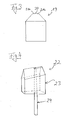
- Figure 1 shows a perspective view of an embodiment of a tool 1 according to the invention with a front side 2, a back 3, a square bottom surface 4 and two side surfaces 5a and 5b.
- the tool 1 shown has the shape of a beveled cuboid on one side and is made of hard plastic.
- the tool 1 is beveled roof-shaped at the top by two opposing bevels 6a, 6b, wherein the cut edge of the two bevels approximately half as a sharp edge 7 and about half is formed as a rounding 8.
- the tool 1 has an inlet opening 9 for the joint material, such as silicone, and an outlet opening 10 for the joint material.
- the two openings 9 and 10 are connected by the channel 11 with each other, which serves as a conduit for the joint material.
- the channel 11 may also serve in the region of the inlet opening 9 as a receptacle for example a cartridge nozzle.
- the channel 11 is cylindrical in the embodiment shown.
- the outlet opening 10 is located between the sharp edge 7 and the rounding 8.
- the two opposing bevels 6a and 6b enclose an angle of 90 °.
- the two cut edges 12a and 12b of the side surfaces 5a and 5b and the chamfers 6a and 6b do not run parallel to the bottom surface 4, but rise from the front side 2 to the back 3 towards.
- the two cut edges 12a and 12b run parallel to the cut edge of the two bevels 6a and 6b, ie to the sharp edges 7 and to the rounding 8, so that the roof-shaped bevel, consisting of the two bevels 6a and 6b, is inclined towards the front side 2.
- Figure 2 shows a slightly perspective side view of the tool according to the invention according to Figure 1 but with a conical channel 13 for the joint material and in use when grouting a joint.
- the chamfered tool 1 When the chamfered tool 1 is inserted into a groove formed at right-angled walls 14a and 14b, the two chamfers 6a and 6b close tightly in the region 15 of the sharp edge 7 with the abutting walls 14a and 14b from.
- a cavity 17 is formed in the shape of the joint to be formed, since the rounding 8 is slightly offset with respect to the sharp edge 7 in the direction of the bottom surface 4.
- the sides 18a and 18b of the resulting cavity are sealed by the two bevels 6a and 6b in the region 16 of the rounding 8.
- Figure 3 shows a rear view of a tool according to the invention, in which the Rounding 8 is located in a recess 20. This shows the two bevels in Region of the rounding 8 on its upper side in each case an edge 21a and 21b. Through this Edges are sealed the sides of the cavity 17 even better.
- FIG. 4 shows a slightly perspective side view of a tool according to the invention 22 with main body 23 and supply pipe 24, wherein the base body 23 and the Supply pipe 24 are integrally connected to each other.
- the basic body corresponds to this embodiment, the tool 1 of Figures 1 and 2, respectively.
- the supply pipe is in This embodiment is flexible.
- FIG. 5 shows a rear view of the tool 1 according to the invention during work with plugged cartridge nozzle 25 from the silicone into the channel 11 penetrates and through the Outlet opening 10 enters the cavity 17.
Landscapes
- Engineering & Computer Science (AREA)
- Architecture (AREA)
- Civil Engineering (AREA)
- Structural Engineering (AREA)
- Physics & Mathematics (AREA)
- Geometry (AREA)
- Mechanical Engineering (AREA)
- Coating Apparatus (AREA)
- Building Environments (AREA)
Applications Claiming Priority (4)
| Application Number | Priority Date | Filing Date | Title |
|---|---|---|---|
| DE10346696 | 2003-10-08 | ||
| DE10346696 | 2003-10-08 | ||
| DE20318048U | 2003-11-21 | ||
| DE20318048U DE20318048U1 (de) | 2003-11-21 | 2003-11-21 | Fugenfertiger |
Publications (2)
| Publication Number | Publication Date |
|---|---|
| EP1522654A2 true EP1522654A2 (fr) | 2005-04-13 |
| EP1522654A3 EP1522654A3 (fr) | 2007-05-23 |
Family
ID=33491685
Family Applications (1)
| Application Number | Title | Priority Date | Filing Date |
|---|---|---|---|
| EP04017936A Withdrawn EP1522654A3 (fr) | 2003-10-08 | 2004-07-29 | Outil pour remplir des joints |
Country Status (2)
| Country | Link |
|---|---|
| EP (1) | EP1522654A3 (fr) |
| DE (1) | DE202004011933U1 (fr) |
Cited By (3)
| Publication number | Priority date | Publication date | Assignee | Title |
|---|---|---|---|---|
| GB2524508A (en) * | 2014-03-25 | 2015-09-30 | Eric Owen | Nozzle arrangement, cartridge for applicator gun, and method of forming bead of sealant or filler |
| EP2942109A1 (fr) * | 2014-04-14 | 2015-11-11 | Rasim Begovic | Dispositif de production de joints entre des composants dispose angulairement |
| EP4291337A1 (fr) * | 2021-02-11 | 2023-12-20 | Bernd Kowalewski | Buse d'application dotée d'une zone de formage élastique pour l'application manuelle d'un boudin d'agent d'étanchéité pâteux dimensionné pour un joint d'étanchéité d'angle |
Family Cites Families (5)
| Publication number | Priority date | Publication date | Assignee | Title |
|---|---|---|---|---|
| US4798502A (en) * | 1985-06-18 | 1989-01-17 | Lily Corporation | Corner grouting nozzle |
| US5257486A (en) * | 1991-04-23 | 1993-11-02 | Adhesives Technology Corporation 1987 | Nozzle for injecting a sealant into a crack |
| EP1353024A3 (fr) * | 2002-04-10 | 2003-11-26 | Nadine Veith | Outil pour déformer des masses à l'état plastique, en particulier pour créer des profilés en saillie |
| DE20318048U1 (de) * | 2003-11-21 | 2004-03-25 | Hoffmann, Christian | Fugenfertiger |
| DE202004002927U1 (de) * | 2004-02-23 | 2004-05-06 | Fetzer, Bernhard | Vorrichtung zum Formen von Fugen |
-
2004
- 2004-07-29 EP EP04017936A patent/EP1522654A3/fr not_active Withdrawn
- 2004-07-29 DE DE202004011933U patent/DE202004011933U1/de not_active Expired - Lifetime
Cited By (3)
| Publication number | Priority date | Publication date | Assignee | Title |
|---|---|---|---|---|
| GB2524508A (en) * | 2014-03-25 | 2015-09-30 | Eric Owen | Nozzle arrangement, cartridge for applicator gun, and method of forming bead of sealant or filler |
| EP2942109A1 (fr) * | 2014-04-14 | 2015-11-11 | Rasim Begovic | Dispositif de production de joints entre des composants dispose angulairement |
| EP4291337A1 (fr) * | 2021-02-11 | 2023-12-20 | Bernd Kowalewski | Buse d'application dotée d'une zone de formage élastique pour l'application manuelle d'un boudin d'agent d'étanchéité pâteux dimensionné pour un joint d'étanchéité d'angle |
Also Published As
| Publication number | Publication date |
|---|---|
| EP1522654A3 (fr) | 2007-05-23 |
| DE202004011933U1 (de) | 2004-11-18 |
Similar Documents
| Publication | Publication Date | Title |
|---|---|---|
| DE69817129T2 (de) | Vorrichtung zum Entfernen von Dichtungssträngen | |
| DE2426322A1 (de) | Spachtel | |
| WO2000012842A1 (fr) | Outil a main permettant d'enlever du materiau pour joints | |
| EP2740861B1 (fr) | Dispositif d'application, de limitation et de lissage de joints injectés manuellement avec masse de scellement plastique | |
| DE19847514B4 (de) | Zwei Werkzeuge zur Verarbeitung, Verdichtung, Glätten und Nachbearbeitung von allen plastischen Fugenmassen | |
| EP2942109B1 (fr) | Dispositif de production de joints entre des composants disposé angulairement | |
| EP3255222B1 (fr) | Dispositif et système de traitement d'une matière de jointoiement | |
| EP1522654A2 (fr) | Outil pour remplir des joints | |
| DE19736985C1 (de) | Kunststoff-Füllstoffspatel/-hobel | |
| EP4375452B1 (fr) | Outil pour la finition et le lissage de joints | |
| DE19808422C2 (de) | Werkzeugsatz zum Verfüllen von Fugen | |
| DE102021103767A1 (de) | Fugenziehaufsatz, Fugenkartusche und Verfahren hierzu | |
| EP1982771A1 (fr) | Dispositif et procédé destinés à l'introduction de produit d'injection | |
| DE10351388B4 (de) | Flexibles Dichtmassen abweisendes Werkzeug | |
| DE9108560U1 (de) | Werkzeug zum Einbringen von Hinterfüllungsmaterial in eine Fuge | |
| DE19826535A1 (de) | Abstreifwerkzeug | |
| DE202008012507U1 (de) | Vorrichtung zum Einbringen von Spachtelmaterial in Fugen | |
| DE3218376C2 (fr) | ||
| DE29602020U1 (de) | Beschlag zum Verbinden von zwei Bauteilen | |
| DE20204737U1 (de) | Werkzeug zum Ausfugen von Fugen, insbesondere Acryl- und Silikonfugen | |
| EP0843764A1 (fr) | Outil pour nettoyage de joints | |
| EP4365388A1 (fr) | Outil de lissage pour le post-traitement d'un joint rempli d'une masse de jointoiement | |
| DE102023128849A1 (de) | Industriemesser mit einem Grundkörper und einem auswechselbaren Schneidenteil | |
| DE202022000314U1 (de) | Auftragsdüse mit einem elastischen Ausformbereich zum manuellen Auftragen eines dimensionierten pastenförmigen Dichtungsmittelstrangs für eine Eckfugenabdichtung | |
| DE9315154U1 (de) | Fliesenlegerkelle |
Legal Events
| Date | Code | Title | Description |
|---|---|---|---|
| PUAI | Public reference made under article 153(3) epc to a published international application that has entered the european phase |
Free format text: ORIGINAL CODE: 0009012 |
|
| AK | Designated contracting states |
Kind code of ref document: A2 Designated state(s): AT BE BG CH CY CZ DE DK EE ES FI FR GB GR HU IE IT LI LU MC NL PL PT RO SE SI SK TR |
|
| AX | Request for extension of the european patent |
Extension state: AL HR LT LV MK |
|
| PUAL | Search report despatched |
Free format text: ORIGINAL CODE: 0009013 |
|
| AK | Designated contracting states |
Kind code of ref document: A3 Designated state(s): AT BE BG CH CY CZ DE DK EE ES FI FR GB GR HU IE IT LI LU MC NL PL PT RO SE SI SK TR |
|
| AX | Request for extension of the european patent |
Extension state: AL HR LT LV MK |
|
| STAA | Information on the status of an ep patent application or granted ep patent |
Free format text: STATUS: THE APPLICATION IS DEEMED TO BE WITHDRAWN |
|
| 18D | Application deemed to be withdrawn |
Effective date: 20070201 |