EP2942109B1 - Dispositif de production de joints entre des composants disposé angulairement - Google Patents
Dispositif de production de joints entre des composants disposé angulairement Download PDFInfo
- Publication number
- EP2942109B1 EP2942109B1 EP15163528.1A EP15163528A EP2942109B1 EP 2942109 B1 EP2942109 B1 EP 2942109B1 EP 15163528 A EP15163528 A EP 15163528A EP 2942109 B1 EP2942109 B1 EP 2942109B1
- Authority
- EP
- European Patent Office
- Prior art keywords
- joint
- components
- edge
- die
- der
- Prior art date
- Legal status (The legal status is an assumption and is not a legal conclusion. Google has not performed a legal analysis and makes no representation as to the accuracy of the status listed.)
- Active
Links
Images



Classifications
-
- B—PERFORMING OPERATIONS; TRANSPORTING
- B05—SPRAYING OR ATOMISING IN GENERAL; APPLYING FLUENT MATERIALS TO SURFACES, IN GENERAL
- B05C—APPARATUS FOR APPLYING FLUENT MATERIALS TO SURFACES, IN GENERAL
- B05C17/00—Hand tools or apparatus using hand held tools, for applying liquids or other fluent materials to, for spreading applied liquids or other fluent materials on, or for partially removing applied liquids or other fluent materials from, surfaces
- B05C17/005—Hand tools or apparatus using hand held tools, for applying liquids or other fluent materials to, for spreading applied liquids or other fluent materials on, or for partially removing applied liquids or other fluent materials from, surfaces for discharging material from a reservoir or container located in or on the hand tool through an outlet orifice by pressure without using surface contacting members like pads or brushes
- B05C17/00503—Details of the outlet element
- B05C17/00516—Shape or geometry of the outlet orifice or the outlet element
-
- B—PERFORMING OPERATIONS; TRANSPORTING
- B05—SPRAYING OR ATOMISING IN GENERAL; APPLYING FLUENT MATERIALS TO SURFACES, IN GENERAL
- B05C—APPARATUS FOR APPLYING FLUENT MATERIALS TO SURFACES, IN GENERAL
- B05C17/00—Hand tools or apparatus using hand held tools, for applying liquids or other fluent materials to, for spreading applied liquids or other fluent materials on, or for partially removing applied liquids or other fluent materials from, surfaces
- B05C17/10—Hand tools for removing partially or for spreading or redistributing applied liquids or other fluent materials, e.g. colour touchers
Definitions
- the present invention relates to a device for producing joints between angularly abutting components by passing the device on the two components in one direction.
- a device which comprises a body comprising an element which comprises a joint facing edge for forming the joint, and which is surrounded on both sides by abutments, which are supported on each of the components, and a Channel which opens into a space arranged in the direction of the element space, which is enclosed by the body and the components, and whose other end is adapted to receive a connection device of a container with grout.
- the injection of the grout and smoothing the joint through the joint facing edge can be done in one operation, which can be saved significantly labor and costs.
- these and similar devices according to the prior art always have planar abutment. This has the significant disadvantage that these devices only work when the joints of the adjacent surfaces plan and possible are exactly right angles. Otherwise, the abutments of the prior art are not properly on and grout can escape laterally, resulting in a dirty joint or the requirement of rework.
- Object of the present invention is therefore to develop the known device in such a way that even on uneven and non-rectangular edges a clean joint can be pulled.
- the abutments comprise two edges running parallel to the joint on both sides of the joint and / or two edges running at an angle, preferably orthogonal to the joint, on both sides of the joint.
- both the two edges running parallel to the joint and the two edges running at an angle to the joint are provided.
- the first-mentioned edges can be advantageously designed to limit the space arranged in the direction in front of the element and thus to enclose the grout substantially in this space.
- the second mentioned edges extending at an angle to the joint may advantageously be intended to serve as a scraper edge for removing grout material exiting the space by stripping the material from the surface of the component concerned.
- the space has a diagonal, round, oval or polygonal, for example, square cross-section perpendicular to the direction of the joint.
- the space is additionally conical in such a way that its diameter decreases towards the element. In this way, by the forward movement in the course of the joint direction, the grout additionally pressed into the joint and prevents leakage of grout forward.
- the joint of the facing edge of the element runs just between the abutments. This allows diagonal joints to be created.
- edge of the element facing the joint runs convex towards the joint.
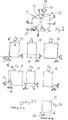
- FIG. 1 shows the application of a below mentioned as a "template” inventive device 10 for producing a joint from a grout 12.
- the device is thereby moved in the direction of the arrow 14 along a joint which extends in the plane of the drawing from left to right.
- the device 10 consists of a substantially cuboidal body, the edge facing the joint has a recess which extends parallel to the edge, and has an approximately semicircular inwardly directed cross section, which is reduced parallel to the joint against the direction of the arrow 14.
- Room diagonal through the body 18 of the device 10 is a channel 20, which opens into a rubber tube 22, which serves to receive the tip 24 of a conventional silicone or acrylic cartridge 26.
- FIG. 2 shows a more detailed representation of the device 10 according to the invention.
- the peel edge 28 is easy to see for simultaneous smoothing of the silicone joint. This is curved in the illustrated embodiment to the outside (on the joint to). It serves to shape the joint surface.
- the Figures 2.1 to 2.6 show the different views of the FIG. 2 shown device from all directions. a denotes the respective joint width in the plane and in height.
- the Figure 2.7 shows the section AA the Figure 2.1
- the Figure 2.8 shows the section BB of Figure 2.4 , In this illustration, the reduction in the depth of the recess 16 is clearly visible.
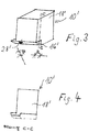
- FIGS. 3 and 4 show another embodiment of the present invention with a diagonal edge 28 '.
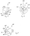
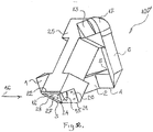
- FIGS. 5 to 10 show three-dimensional representations of another device according to the invention, which is in contrast to the above-described device also applicable to joints that are bounded by non-perpendicular surfaces, since the corresponding device rests only along a respective edge 110 on the surfaces bounding the joint. Furthermore, a clear demarcation of the joint is produced by the edges 110 and the scrapers 130 with a respective scraper edge 131 arranged next to the edges 110, namely outside the edges 110 in the direction of movement at the end of the device, can nevertheless remove joint material that has emerged laterally along the edges 110, so that with the preferred embodiment of the device according to the invention clean joints can be made even if the surfaces to be grouted are not exactly perpendicular to each other or have unevenness.
- the device is designed mirror-symmetrically about a space-diagonal surface, wherein the one room diagonal half has a straight joint termination with a straight edge 128, while the other half-space half a convexly curved conclusion for inwardly curved joints with a circular sector-shaped edge 128 'has.
- the feed opening 20 for the supply of the joint material also extends across the room by the device 100 according to the invention, so that by reversing the device on the silicone or acrylic syringe each of the opposite halves of the space diagonal mirror image device 100 are activated and either curved inwards or smooth joints can be made.
- the outer side of the edges 28, 128, 128 ', 11, 23 or / and the outer sides of the edges 110, 110', 7, 8, 21, 22 of the present invention may preferably be a thin, wettable one Sponge coated by the addition of a crawling of the grout around the edges and a setting of the grout on the outside of the edges can be prevented.
- This invention can be used in all fields where silicone, acrylic, adhesive is used, especially in the construction, metal, automotive industries.
- the system operation is very simple.
- the stencil is held on one side and a silicone syringe on the other.
- the silicone runs through the rubber tube and through the template into the conical opening in the lower part of the template.
- the template is moved in the desired direction.
- the template must be moved forward before the material exits, so the desired shape is retained.
- Stencils can be made of different shapes and different materials.
- the rubber hose turns around its own axis.
- the tapered portion of the template allows for easy movement of the material forward in the direction in which the template moves.
- Templates can move from right to left, from left to right, from bottom to top, and from top to bottom.
Landscapes
- Physics & Mathematics (AREA)
- Geometry (AREA)
- Engineering & Computer Science (AREA)
- Mechanical Engineering (AREA)
- Moulds For Moulding Plastics Or The Like (AREA)
- Consolidation Of Soil By Introduction Of Solidifying Substances Into Soil (AREA)
- Road Paving Structures (AREA)
Claims (7)
- Dispositif (10 ; 10' ; 100 ; 100') pour produire des joints entre des composants se rencontrant sous un angle en guidant le dispositif le long des composants dans une direction (14) avec un corps (18 ; 18' ; 118 ; 25) qui comporte un élément avec un bord (28 ; 128 ; 128' ; 11 ; 23) faisant face au joint pour former le joint, qui est entouré des deux côtés par des butées qui sont chacune supportées sur l'un des composants, et comprend un canal (20) qui s'ouvre dans un espace (16) disposé dans la direction (14) devant l'élément et qui est entouré par le corps (18 ; 18' ; 118 ; 25) et les composants, et dont l'autre extrémité (22) est adaptée pour recevoir un dispositif de liaison d'un récipient (26) avec du mastic, caractérisé en ce que les butées sont constituées de deux bords (110) parallèles au joint des deux côtés du joint et deux bords (131) formant un angle, de préférence perpendiculaire au joint, des deux côtés du joint.
- Dispositif (10) selon la revendication 1, caractérisé en ce que l'espace (16) présente une section transversale coupée en diagonale, ronde, ovale ou polygonale, par exemple carrée, perpendiculaire à la direction (14).
- Dispositif (10) selon la revendication 2, caractérisé en ce que l'espace (16) est en outre conique de telle sorte que son diamètre diminue vers l'élément.
- Dispositif (10) selon l'une des revendications 1 à 3, caractérisé en ce que le bord (28) de l'élément tourné vers le joint s'étend droit entre les butées.
- Dispositif (10) selon l'une des revendications 1 à 4, caractérisé en ce que le bord (28) de l'élément tourné vers le joint s'étend incurvé convexe vers le joint.
- Dispositif selon l'une des revendications 1 à 5, caractérisé en ce que le corps (25) est déformable élastiquement de telle sorte que les butées peuvent s'adapter à un angle qui s'écarte d'un angle standard entre les composants qui se rencontrent.
- Dispositif selon l'une des revendications 1 à 6, caractérisé par au moins un élément éponge humidifiable sur un côté extérieur du corps adjacent à un bord ou une surface de pilier.
Applications Claiming Priority (1)
| Application Number | Priority Date | Filing Date | Title |
|---|---|---|---|
| DE202014003184.3U DE202014003184U1 (de) | 2014-04-14 | 2014-04-14 | Vorrichtung zur Herstellung von Fugen zwischen im Winkel aufeinander stoßenden Bauteilen |
Publications (2)
| Publication Number | Publication Date |
|---|---|
| EP2942109A1 EP2942109A1 (fr) | 2015-11-11 |
| EP2942109B1 true EP2942109B1 (fr) | 2019-12-11 |
Family
ID=52009305
Family Applications (1)
| Application Number | Title | Priority Date | Filing Date |
|---|---|---|---|
| EP15163528.1A Active EP2942109B1 (fr) | 2014-04-14 | 2015-04-14 | Dispositif de production de joints entre des composants disposé angulairement |
Country Status (2)
| Country | Link |
|---|---|
| EP (1) | EP2942109B1 (fr) |
| DE (1) | DE202014003184U1 (fr) |
Families Citing this family (4)
| Publication number | Priority date | Publication date | Assignee | Title |
|---|---|---|---|---|
| JP7152929B2 (ja) * | 2018-10-11 | 2022-10-13 | 株式会社Subaru | シール材吐出ノズルおよびシール材吐出装置 |
| JP7152928B2 (ja) * | 2018-10-11 | 2022-10-13 | 株式会社Subaru | シール材吐出ノズルおよびシール材吐出装置 |
| JP7152930B2 (ja) * | 2018-10-11 | 2022-10-13 | 株式会社Subaru | シール材吐出ノズルおよびシール材吐出装置 |
| DE102021000704B4 (de) * | 2021-02-11 | 2023-09-14 | Bernd Kowalewski | Auftragsdüse mit einem elastischen Ausformbereich zum manuellen Auftragen eines dimensionierten pastenförmigen Dichtungsmittelstrangs für eine Eckfugenabdichtung |
Family Cites Families (5)
| Publication number | Priority date | Publication date | Assignee | Title |
|---|---|---|---|---|
| US3559234A (en) * | 1969-01-08 | 1971-02-02 | Dow Corning | Corner tool and applicator nozzle |
| DE7812552U1 (de) * | 1978-04-19 | 1978-09-14 | Zern Klaus | Vorrichtung zum Ein- und Aufbringen von verschiedenen Materialien aus Kartuschen o dgl |
| US5622728A (en) * | 1993-09-08 | 1997-04-22 | Thomas P. Mahoney | Wiping device for caulking, and method of forming same |
| EP1522654A3 (fr) * | 2003-10-08 | 2007-05-23 | Christian Hoffmann | Outil pour remplir des joints |
| DE202013003380U1 (de) * | 2013-04-11 | 2013-05-31 | Hasan Balci | Spritztülle für plastische Verfugungsmassen |
-
2014
- 2014-04-14 DE DE202014003184.3U patent/DE202014003184U1/de not_active Expired - Lifetime
-
2015
- 2015-04-14 EP EP15163528.1A patent/EP2942109B1/fr active Active
Non-Patent Citations (1)
| Title |
|---|
| None * |
Also Published As
| Publication number | Publication date |
|---|---|
| DE202014003184U1 (de) | 2014-11-05 |
| EP2942109A1 (fr) | 2015-11-11 |
Similar Documents
| Publication | Publication Date | Title |
|---|---|---|
| DE2426322A1 (de) | Spachtel | |
| EP2942109B1 (fr) | Dispositif de production de joints entre des composants disposé angulairement | |
| EP3255222B1 (fr) | Dispositif et système de traitement d'une matière de jointoiement | |
| EP0711887A1 (fr) | Outil pour la finition des joints en jointoyage élastique permanent | |
| DE202013003380U1 (de) | Spritztülle für plastische Verfugungsmassen | |
| DE2642783A1 (de) | Vorrichtung zum auftragen von verputz | |
| EP3891353B1 (fr) | Procédé et dispositif de fabrication d'intercalaires thermoplastiques | |
| DE2809283C2 (de) | Vorrichtung zum Beschichten von Bleistiften | |
| EP1666683B1 (fr) | Outil pour la finition et le lissage des joints remplis avec un jointage élastique permanent | |
| EP2363564B1 (fr) | Buse de collage pour l'utilisation dans le collage d'un agencement de disques sur un profilé pour fenêtres et portes | |
| EP4375452B1 (fr) | Outil pour la finition et le lissage de joints | |
| EP3434844B1 (fr) | Chariot à mortier | |
| DE102018122840A1 (de) | Vorrichtung zum Verarbeiten von Kleb- und Dichtstoffen | |
| DE102010045992A1 (de) | Verfugungswerkzeug | |
| AT406979B (de) | Verfahren zum auftragen eines thermoplastischen abstandhalters auf eine glasscheibe im zuge der herstellung von isolierglasscheiben und zum durchführen des verfahrens verwendbare düse | |
| DE202021105473U1 (de) | Düse, Düsenanordnung und Vorrichtung zum Einbringen eines pastösen Mediums in eine Gehrungsfuge | |
| DE102021000704B4 (de) | Auftragsdüse mit einem elastischen Ausformbereich zum manuellen Auftragen eines dimensionierten pastenförmigen Dichtungsmittelstrangs für eine Eckfugenabdichtung | |
| DE10351388B4 (de) | Flexibles Dichtmassen abweisendes Werkzeug | |
| DE9108560U1 (de) | Werkzeug zum Einbringen von Hinterfüllungsmaterial in eine Fuge | |
| DE102021103767A1 (de) | Fugenziehaufsatz, Fugenkartusche und Verfahren hierzu | |
| DE202022106549U1 (de) | Werkzeug zum Nacharbeiten und Glätten von Fugen | |
| EP1522654A2 (fr) | Outil pour remplir des joints | |
| EP1982771A1 (fr) | Dispositif et procédé destinés à l'introduction de produit d'injection | |
| DE29603258U1 (de) | Metallprofil für die Bildung von Rahmenwerken mit Eckverbindungen | |
| DE202008012507U1 (de) | Vorrichtung zum Einbringen von Spachtelmaterial in Fugen |
Legal Events
| Date | Code | Title | Description |
|---|---|---|---|
| PUAI | Public reference made under article 153(3) epc to a published international application that has entered the european phase |
Free format text: ORIGINAL CODE: 0009012 |
|
| AK | Designated contracting states |
Kind code of ref document: A1 Designated state(s): AL AT BE BG CH CY CZ DE DK EE ES FI FR GB GR HR HU IE IS IT LI LT LU LV MC MK MT NL NO PL PT RO RS SE SI SK SM TR |
|
| AX | Request for extension of the european patent |
Extension state: BA ME |
|
| 17P | Request for examination filed |
Effective date: 20160504 |
|
| RBV | Designated contracting states (corrected) |
Designated state(s): AL AT BE BG CH CY CZ DE DK EE ES FI FR GB GR HR HU IE IS IT LI LT LU LV MC MK MT NL NO PL PT RO RS SE SI SK SM TR |
|
| GRAP | Despatch of communication of intention to grant a patent |
Free format text: ORIGINAL CODE: EPIDOSNIGR1 |
|
| STAA | Information on the status of an ep patent application or granted ep patent |
Free format text: STATUS: GRANT OF PATENT IS INTENDED |
|
| RIC1 | Information provided on ipc code assigned before grant |
Ipc: B05C 17/005 20060101AFI20190503BHEP Ipc: B05C 17/10 20060101ALN20190503BHEP |
|
| INTG | Intention to grant announced |
Effective date: 20190529 |
|
| GRAS | Grant fee paid |
Free format text: ORIGINAL CODE: EPIDOSNIGR3 |
|
| GRAA | (expected) grant |
Free format text: ORIGINAL CODE: 0009210 |
|
| STAA | Information on the status of an ep patent application or granted ep patent |
Free format text: STATUS: THE PATENT HAS BEEN GRANTED |
|
| AK | Designated contracting states |
Kind code of ref document: B1 Designated state(s): AL AT BE BG CH CY CZ DE DK EE ES FI FR GB GR HR HU IE IS IT LI LT LU LV MC MK MT NL NO PL PT RO RS SE SI SK SM TR |
|
| REG | Reference to a national code |
Ref country code: GB Ref legal event code: FG4D Free format text: NOT ENGLISH |
|
| REG | Reference to a national code |
Ref country code: CH Ref legal event code: EP |
|
| REG | Reference to a national code |
Ref country code: AT Ref legal event code: REF Ref document number: 1211672 Country of ref document: AT Kind code of ref document: T Effective date: 20191215 |
|
| REG | Reference to a national code |
Ref country code: DE Ref legal event code: R096 Ref document number: 502015011172 Country of ref document: DE |
|
| REG | Reference to a national code |
Ref country code: IE Ref legal event code: FG4D Free format text: LANGUAGE OF EP DOCUMENT: GERMAN |
|
| REG | Reference to a national code |
Ref country code: NL Ref legal event code: MP Effective date: 20191211 |
|
| REG | Reference to a national code |
Ref country code: LT Ref legal event code: MG4D |
|
| PG25 | Lapsed in a contracting state [announced via postgrant information from national office to epo] |
Ref country code: LV Free format text: LAPSE BECAUSE OF FAILURE TO SUBMIT A TRANSLATION OF THE DESCRIPTION OR TO PAY THE FEE WITHIN THE PRESCRIBED TIME-LIMIT Effective date: 20191211 Ref country code: SE Free format text: LAPSE BECAUSE OF FAILURE TO SUBMIT A TRANSLATION OF THE DESCRIPTION OR TO PAY THE FEE WITHIN THE PRESCRIBED TIME-LIMIT Effective date: 20191211 Ref country code: NO Free format text: LAPSE BECAUSE OF FAILURE TO SUBMIT A TRANSLATION OF THE DESCRIPTION OR TO PAY THE FEE WITHIN THE PRESCRIBED TIME-LIMIT Effective date: 20200311 Ref country code: GR Free format text: LAPSE BECAUSE OF FAILURE TO SUBMIT A TRANSLATION OF THE DESCRIPTION OR TO PAY THE FEE WITHIN THE PRESCRIBED TIME-LIMIT Effective date: 20200312 Ref country code: LT Free format text: LAPSE BECAUSE OF FAILURE TO SUBMIT A TRANSLATION OF THE DESCRIPTION OR TO PAY THE FEE WITHIN THE PRESCRIBED TIME-LIMIT Effective date: 20191211 Ref country code: BG Free format text: LAPSE BECAUSE OF FAILURE TO SUBMIT A TRANSLATION OF THE DESCRIPTION OR TO PAY THE FEE WITHIN THE PRESCRIBED TIME-LIMIT Effective date: 20200311 Ref country code: FI Free format text: LAPSE BECAUSE OF FAILURE TO SUBMIT A TRANSLATION OF THE DESCRIPTION OR TO PAY THE FEE WITHIN THE PRESCRIBED TIME-LIMIT Effective date: 20191211 |
|
| PG25 | Lapsed in a contracting state [announced via postgrant information from national office to epo] |
Ref country code: RS Free format text: LAPSE BECAUSE OF FAILURE TO SUBMIT A TRANSLATION OF THE DESCRIPTION OR TO PAY THE FEE WITHIN THE PRESCRIBED TIME-LIMIT Effective date: 20191211 Ref country code: HR Free format text: LAPSE BECAUSE OF FAILURE TO SUBMIT A TRANSLATION OF THE DESCRIPTION OR TO PAY THE FEE WITHIN THE PRESCRIBED TIME-LIMIT Effective date: 20191211 |
|
| PG25 | Lapsed in a contracting state [announced via postgrant information from national office to epo] |
Ref country code: AL Free format text: LAPSE BECAUSE OF FAILURE TO SUBMIT A TRANSLATION OF THE DESCRIPTION OR TO PAY THE FEE WITHIN THE PRESCRIBED TIME-LIMIT Effective date: 20191211 |
|
| PG25 | Lapsed in a contracting state [announced via postgrant information from national office to epo] |
Ref country code: PT Free format text: LAPSE BECAUSE OF FAILURE TO SUBMIT A TRANSLATION OF THE DESCRIPTION OR TO PAY THE FEE WITHIN THE PRESCRIBED TIME-LIMIT Effective date: 20200506 Ref country code: EE Free format text: LAPSE BECAUSE OF FAILURE TO SUBMIT A TRANSLATION OF THE DESCRIPTION OR TO PAY THE FEE WITHIN THE PRESCRIBED TIME-LIMIT Effective date: 20191211 Ref country code: RO Free format text: LAPSE BECAUSE OF FAILURE TO SUBMIT A TRANSLATION OF THE DESCRIPTION OR TO PAY THE FEE WITHIN THE PRESCRIBED TIME-LIMIT Effective date: 20191211 Ref country code: CZ Free format text: LAPSE BECAUSE OF FAILURE TO SUBMIT A TRANSLATION OF THE DESCRIPTION OR TO PAY THE FEE WITHIN THE PRESCRIBED TIME-LIMIT Effective date: 20191211 Ref country code: NL Free format text: LAPSE BECAUSE OF FAILURE TO SUBMIT A TRANSLATION OF THE DESCRIPTION OR TO PAY THE FEE WITHIN THE PRESCRIBED TIME-LIMIT Effective date: 20191211 Ref country code: ES Free format text: LAPSE BECAUSE OF FAILURE TO SUBMIT A TRANSLATION OF THE DESCRIPTION OR TO PAY THE FEE WITHIN THE PRESCRIBED TIME-LIMIT Effective date: 20191211 |
|
| PG25 | Lapsed in a contracting state [announced via postgrant information from national office to epo] |
Ref country code: SM Free format text: LAPSE BECAUSE OF FAILURE TO SUBMIT A TRANSLATION OF THE DESCRIPTION OR TO PAY THE FEE WITHIN THE PRESCRIBED TIME-LIMIT Effective date: 20191211 Ref country code: SK Free format text: LAPSE BECAUSE OF FAILURE TO SUBMIT A TRANSLATION OF THE DESCRIPTION OR TO PAY THE FEE WITHIN THE PRESCRIBED TIME-LIMIT Effective date: 20191211 Ref country code: IS Free format text: LAPSE BECAUSE OF FAILURE TO SUBMIT A TRANSLATION OF THE DESCRIPTION OR TO PAY THE FEE WITHIN THE PRESCRIBED TIME-LIMIT Effective date: 20200411 |
|
| REG | Reference to a national code |
Ref country code: DE Ref legal event code: R097 Ref document number: 502015011172 Country of ref document: DE |
|
| PLBE | No opposition filed within time limit |
Free format text: ORIGINAL CODE: 0009261 |
|
| STAA | Information on the status of an ep patent application or granted ep patent |
Free format text: STATUS: NO OPPOSITION FILED WITHIN TIME LIMIT |
|
| PG25 | Lapsed in a contracting state [announced via postgrant information from national office to epo] |
Ref country code: DK Free format text: LAPSE BECAUSE OF FAILURE TO SUBMIT A TRANSLATION OF THE DESCRIPTION OR TO PAY THE FEE WITHIN THE PRESCRIBED TIME-LIMIT Effective date: 20191211 |
|
| 26N | No opposition filed |
Effective date: 20200914 |
|
| PG25 | Lapsed in a contracting state [announced via postgrant information from national office to epo] |
Ref country code: SI Free format text: LAPSE BECAUSE OF FAILURE TO SUBMIT A TRANSLATION OF THE DESCRIPTION OR TO PAY THE FEE WITHIN THE PRESCRIBED TIME-LIMIT Effective date: 20191211 Ref country code: MC Free format text: LAPSE BECAUSE OF FAILURE TO SUBMIT A TRANSLATION OF THE DESCRIPTION OR TO PAY THE FEE WITHIN THE PRESCRIBED TIME-LIMIT Effective date: 20191211 |
|
| REG | Reference to a national code |
Ref country code: CH Ref legal event code: PL |
|
| PG25 | Lapsed in a contracting state [announced via postgrant information from national office to epo] |
Ref country code: FR Free format text: LAPSE BECAUSE OF NON-PAYMENT OF DUE FEES Effective date: 20200430 Ref country code: LU Free format text: LAPSE BECAUSE OF NON-PAYMENT OF DUE FEES Effective date: 20200414 Ref country code: IT Free format text: LAPSE BECAUSE OF FAILURE TO SUBMIT A TRANSLATION OF THE DESCRIPTION OR TO PAY THE FEE WITHIN THE PRESCRIBED TIME-LIMIT Effective date: 20191211 Ref country code: LI Free format text: LAPSE BECAUSE OF NON-PAYMENT OF DUE FEES Effective date: 20200430 Ref country code: CH Free format text: LAPSE BECAUSE OF NON-PAYMENT OF DUE FEES Effective date: 20200430 |
|
| REG | Reference to a national code |
Ref country code: BE Ref legal event code: MM Effective date: 20200430 |
|
| PG25 | Lapsed in a contracting state [announced via postgrant information from national office to epo] |
Ref country code: PL Free format text: LAPSE BECAUSE OF FAILURE TO SUBMIT A TRANSLATION OF THE DESCRIPTION OR TO PAY THE FEE WITHIN THE PRESCRIBED TIME-LIMIT Effective date: 20191211 Ref country code: BE Free format text: LAPSE BECAUSE OF NON-PAYMENT OF DUE FEES Effective date: 20200430 |
|
| GBPC | Gb: european patent ceased through non-payment of renewal fee |
Effective date: 20200414 |
|
| PG25 | Lapsed in a contracting state [announced via postgrant information from national office to epo] |
Ref country code: IE Free format text: LAPSE BECAUSE OF NON-PAYMENT OF DUE FEES Effective date: 20200414 Ref country code: GB Free format text: LAPSE BECAUSE OF NON-PAYMENT OF DUE FEES Effective date: 20200414 |
|
| REG | Reference to a national code |
Ref country code: AT Ref legal event code: MM01 Ref document number: 1211672 Country of ref document: AT Kind code of ref document: T Effective date: 20200414 |
|
| PG25 | Lapsed in a contracting state [announced via postgrant information from national office to epo] |
Ref country code: AT Free format text: LAPSE BECAUSE OF NON-PAYMENT OF DUE FEES Effective date: 20200414 |
|
| PG25 | Lapsed in a contracting state [announced via postgrant information from national office to epo] |
Ref country code: TR Free format text: LAPSE BECAUSE OF FAILURE TO SUBMIT A TRANSLATION OF THE DESCRIPTION OR TO PAY THE FEE WITHIN THE PRESCRIBED TIME-LIMIT Effective date: 20191211 Ref country code: MT Free format text: LAPSE BECAUSE OF FAILURE TO SUBMIT A TRANSLATION OF THE DESCRIPTION OR TO PAY THE FEE WITHIN THE PRESCRIBED TIME-LIMIT Effective date: 20191211 Ref country code: CY Free format text: LAPSE BECAUSE OF FAILURE TO SUBMIT A TRANSLATION OF THE DESCRIPTION OR TO PAY THE FEE WITHIN THE PRESCRIBED TIME-LIMIT Effective date: 20191211 |
|
| PG25 | Lapsed in a contracting state [announced via postgrant information from national office to epo] |
Ref country code: MK Free format text: LAPSE BECAUSE OF FAILURE TO SUBMIT A TRANSLATION OF THE DESCRIPTION OR TO PAY THE FEE WITHIN THE PRESCRIBED TIME-LIMIT Effective date: 20191211 |
|
| PGFP | Annual fee paid to national office [announced via postgrant information from national office to epo] |
Ref country code: DE Payment date: 20220426 Year of fee payment: 8 |
|
| REG | Reference to a national code |
Ref country code: DE Ref legal event code: R119 Ref document number: 502015011172 Country of ref document: DE |
|
| PG25 | Lapsed in a contracting state [announced via postgrant information from national office to epo] |
Ref country code: DE Free format text: LAPSE BECAUSE OF NON-PAYMENT OF DUE FEES Effective date: 20231103 |